- Home
- Product Categories
- Current
- AttoPilot Voltage and Current Sense Breakout - 90A

AttoPilot Voltage and Current Sense Breakout - 90A
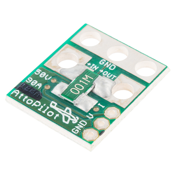
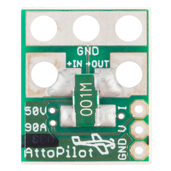
This is a small voltage and current sense PCB. DC current is determined by measuring a voltage drop across a pair of parallel 1 mOhm shunt resistors, then converted to a final analog voltage output by the TI INA-169. Voltage sense is accomplished by scaling to 3.3V ADC range by a precision resistor divider.
The PCB is supplied without leads or connectors. The pad sizes are large enough to accommodate 12 gauge heavy duty leads (see datasheet) but care must be exercised in soldering. Smaller gauge leads are considerably easier to solder without creating shorts.
- 51.8V Max
- 89.4A Max
- Very low zero current offset
- Analog output scaled for 3.3V ADC
- Self Powered
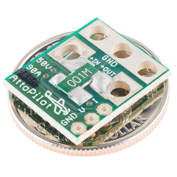
- 4 x 15 x 19mm
- [Datasheet](http://cdn.sparkfun.com/datasheets/Sensors/Current/DC Voltage and Current Sense PCB with Analog Output.pdf)
- Example Sketch
AttoPilot Voltage and Current Sense Breakout - 90A Product Help and Resources
Unusual Current Readings
From the datasheet,
"The output impedance of the INA169 OUT terminal is very high, which permits using values up to 100kΩ with excellent accuracy. The input impedance of any additional circuitry at the output must be much higher than the value of RL to avoid degrading accuracy".
If a you are seeing crazy current readings, this is the likely cause. An impedance converting circuit, such as an op-amp, will probably solve those issues. See this thread => https://forums.openpilot.org/topic/37838-attopilot-battery-monitor/#entry331962 .
Example used an AD8066 SO8. From the thread,
"Pin 8 (V+) is soldered to the shunt resistor. Pin 4 (GND) is soldered to the sensor board ground plane (I scratched off the solder resist only in this area. This was the trickiest part for me because your have to be sure not to scrape off too much and thus short-circuit with Pin 3 later). Pin 3 (+IN) goes to I-out of the AttoPilot, and the wire to the [microcontroller] Board (which is normally soldered to the I-out of the AttoPilot) goes to Pin 1 AND 2.
I first soldered Pin 1+2 and Pin 3 and then placed the opamp on the sensor board and soldered Pin 4 and 8. After all I secured everything with plastik spray which crawls even in the darkest corner (low viscosity superglue should also do the job)."
Here is an image of the modified current sensor => https://drive.google.com/open?id=0B0jwgLkjMWzDUTNLdTR5ZFRmQlE
The designer is aware of this, see comment => https://www.sparkfun.com/products/9028#comment-5367a7fbce395fdd458b456f ] .
Core Skill: Soldering
This skill defines how difficult the soldering is on a particular product. It might be a couple simple solder joints, or require special reflow tools.
Skill Level: Noob - Some basic soldering is required, but it is limited to a just a few pins, basic through-hole soldering, and couple (if any) polarized components. A basic soldering iron is all you should need.
See all skill levels
Core Skill: Electrical Prototyping
If it requires power, you need to know how much, what all the pins do, and how to hook it up. You may need to reference datasheets, schematics, and know the ins and outs of electronics.
Skill Level: Competent - You will be required to reference a datasheet or schematic to know how to use a component. Your knowledge of a datasheet will only require basic features like power requirements, pinouts, or communications type. Also, you may need a power supply that?s greater than 12V or more than 1A worth of current.
See all skill levels
Comments
Looking for answers to technical questions?
We welcome your comments and suggestions below. However, if you are looking for solutions to technical questions please see our Technical Assistance page.
Customer Reviews
4.6 out of 5
Based on 5 ratings:
Great Little Board
The first board that I bought I changed my setup three times, the last time I used a little too much solder and too much heat that I shorted out the ground trace. (you can see the trace in the picture directly under the N in GND where the ground power wire is soldered to the board) By simply adding a jumper from the power lead ground and the instrument ground lead made for an easy fix, thanks to the great documentation that has been made available.
It takes a beating from ham handed soldering and still works flawlessly. I bought two more of these, since this little board will make for one of the cheapest 90A current probes for general multimeter use that I have ever seen.
Works as planned!
If you follow the instructions on the Ardupilot wiki:
http://copter.ardupilot.com/wiki/common-optional-hardware/common-powermodule-landingpage/common-using-a-pixhawk-with-6s-batteries/
It works perfectly. Thanks guys!
Great board
Even with the heat required to solder the large gauge wires, the pcb lands showed no sign of delaminating. Then correction factors in the example code worked well and verified against test equipment. I will purchase again.
Works Exactly As Advertised
Works Exactly As Advertised
SOISentinel - This sensor was made for RC airplane application (UAV actually) where 14 and 12 gauge wire is typical, and when I ship this with an autopilot the 12 gauge wires come pre-soldered. All the end-user has to do is solder on Deans Ultra or Power Pole connectors. You are right in that as far as the sensor is concerned, only a tiny common ground need to be connected back to the power sourse and load.
Also, I am now out of stock of my original 500 PCB batch, and this is being re-designed to be larger in some ways, specifically more space between both the "+" and the GND and with notches in the PCB so that Deans connectors can be soldered direct to the PCB.
This won't handle 24VDC up to 120A, would it? I saw your note that you're scaling up the board... would love to have something exactly like this for 6S1P lipo or larger.
6s LiPo (only 25.8 volts at peak) is well within the range of this sensor if keeping analog output max within the 0-3.3V output. But current range - no, not this sensor as shown on this page.
Tell Sparkfun that you want a higher current version, BECAUSE today as I ship another 150 of these to SFE, I am including 2 samples of a 180 Amp sensor (51.8V). Time to time I get requests for higher current version.
I also sent them 1 sample of a 45A/13.3V unit. I don't see why they won't start stocking them if the interest is there.
Thx, Dean G.
put together a quick video. it shows one way to test the circuit. http://www.youtube.com/watch?v=sTMkwKfbSzk
Fantastic, this helped a lot. Thanks!
I've just had one of these blow up on me when drawing around 30A @ 48 Volts. From the looks of it, the traces on both shunt resistors. What I don't understand is how those traces are supposed to be able to handle up to 89.4 Amps @ 51.8 Volts. Is there a power rating that isn't listed for these that I've gone over? Seems like an awfully large amount of current for such small traces.
I hate to reply to myself, but after a bit more research, I think that the wrong resistor was mounted to this board. The data sheet says that it should be two 500uOhm resistors, not two 001M (1mOhm) resistors for the 90A version. Mine one clearly had two 001M resistors. Could this be the problem? EDIT: Just realized these are in parallel, whereas there is only the one on the 45A boards, and 4 on the 180A boards.
It's recommended to flood the pads with solder between shunts and your leads. These boards receive manual solder flooding as final assembly step, however variations in amount of flooding do occur.
Hi,
Reading through the comments, it must be me, I dont know what I am doing wrong but I am having a hard time getting these 180a ver boards to work (the current sense). I got a couple of these to work but have 5 that do not work. I recently tried the Chinese version, even adding shunts to their 90a version and they still work for me. Problem I am seeing is, I solder connectors on and either I will get like 2v on the current sense pin slowly rising to about 1v under input voltage, or I just get bad readings (different amps per volt, usually really high) I have even changed the INA169 on a few but end up with the same problem. any idea what I could have done wrong, Ive looked for shorts/opens.. just cant figure what is going on. thanks
They really need to dope the insides of those notches so solder will stick. Also, I'd love it if this board could take bullet connectors more easily. I don't necessarily want to have to use Deans connectors with these. Otherwise, great board! :D
dmgoedde,
I want to point you to some findings with the ATTOPILOT sensor which are actually discussed on the openpilot-forum: http://forums.openpilot.org/topic/37838-attopilot-battery-monitor/?p=331962
Would be great if you can comment this.
Greetings Nick
Thank you, that was helpful. The added OpAmp serves as amplifier into external circuits, overcoming impedance unknowns of external circuits and delivering the full output analog signal into user's ADC. The AttoPilot sensor is designed per spec sheet of the components with focus on small size for use in small UAVs. Additional circuitry that's not strictly required, per se, has been omitted. However - given the wide use in some popular UAVs, it's smart to ensure ease of use w/o need to consider unknowns. I will take this into serious consideration for a design update post-depletion of my present stock of PCB panels. Thank you very much for the feedback!
The 73.2k resistor on Isense output pin of INA169 is not a source of series impedence... it is a shunt to GND that converts the INA169's output (which is actually current) into an analog voltage signal. This is described in the spec sheet for INA169. It's sometimes required for ADCs to use an amplifier pre-conditioner, which amounts to an Op-Amp with output tied to input reference... it provides extra muscle to ensure analog input is passed into the ADC with minimal attenuation. I'd suggest it as a very good idea for all products with ADC, such as hobby autopilots, to use ADC amplifiers between outside world and the ADC. ADC amplifiers are available as multi-channel ICs in small packages. If instead the amplifier were added to these simple AttoPilot boards this would also necessitate adding a voltage regulator and additional passives. A voltage regulator that accepts up to 50 volts and supplies an IC at say 3.3V is a large Vdrop for a compact cheap linear regulator and would waste approx (50-3.3)/50 of power drawn through the Vreg circuit powering the ADC amplifier... switching regulator would be more expensive and most likely require inductor and complication of more expensive high speed switching diode to avoid excessive leakage at the 120+ deg F likely to be experienced by this PCB... versus a cheaper Schottky diode in the switch Vreg circuit. Basically, the goal has been to keep this sensor small and simple as possible. I'm am, however, very open to new components in the future that can improve this PCB.
How can I modify it to support up to 70V?
Could be difficult: INA169 is powered by in+ to GND, and 70V is above spec'd limit of INA169. A crude approach that I wouldn't recommend is cut the trace between +in and INA supply input, then use resistor divider between +in and supply to INA169... would have to stay within power dissipation limits of added divider while supplying enough current to INA169. Cans of worms. Better approach would be voltage regulator, however at 70 V would probably need to keep Vdrop across regulator small. Another option is between +in and supply to INA169 insert several silicon diodes in series to drop the voltage about 1.5V/diode, using the # of diodes to reduce voltage to under INA169 upper limit. However that still requires cutting a tiny trace but doable with a razor blade tip. Please take my comments with a grain of salt, depending on your personal comfort level doing ad-hoc modification of circuits. I cannot accept liability for undesirable results to performance or safety.
Would there be a way to combine the V and A sensing outputs into the APM so that one of these units could be used on each set of battery leads (in a two battery. parallel installation) thereby doubling the current capacity of the overall system that they'd work in?
I also had a need to measure bi-directional current, and after looking at the ina-169 datasheet and some trial and error, was able to do it with two of these boards after a small modification.
One board has the power leads attached as shown in the datasheet. The other board has its shunt resistors removed and no power leads attached. Then using short pieces of wire, connect the shunt resistor sense pad on the Vin side of the first board to the now-empty sense pad on the Vout side of the second board. Repeat for the other sense pads.
This configuration retains the same analog output values as a single board. Since you now have two separate boards each measuring current in a single direction, you also have two separate Iout lines. Refer to the examples in the ina-169 datasheet if you need to combine both signals into a single +/- signal line. For mine, I simply connect each line to an analog input on an Arduino and do the combining in software.
If you don't want to remove the shunt resistors on one of the boards, then you will need to attach power leads to both boards, still connect the sense pads together as above, and then use the analog output parameter values for the next higher board in your code (i.e. for 90A boards, use the 18.3mV/A rating from the 180A board). Make sure the power leads on each side of the board are the same lengh between the board and where they ultimately come together, otherwise you may end up with slightly more current going through one board than the other which will skew your output.
Would you be able to provide a diagram of the connections and modifications you made for this usage? I think I follow your text, but don't want to make any mistakes.
Thanks B
Hi. Can I use this shield to only mesure my home current consumption ? (220V) Thanks.
Hi, sorry no this is only for measuring DC current up to 90 Amps. However, the spec sheet for the INA169 IC by Texas Instruments shows a circuit layout using two INA169 for measuring AC current. You can find that spec sheet by going to www.digikey.com and searching for "INA169".
Disclaimer: I have not made an AC current sensing prototype using the INA169.
Just got one of these from a reseller in Japan where I live. Disappointed to see no current output at all. Voltage is fine. Some old posts mention that this happened, and one guy blamed himself for damaging it... I know I can't be certain, but I think it's very unlikely I overheated anything. Used a 20 watt iron with 1.0mm dia. wire. I'm trying to measure small solar panel output @ 18V 1A max, hence the thin wire.
But my question is, was this found to be a common fault? Or is the only likely explanation that I damaged the TI chip?
I'm willing to buy another one if I get some idea of how likely it is it work if I'm EXTRA careful...
Hi - I personally use a 200 Watt solder station. With such high power it's possible to solder very quickly and reduce heating the rest of the board. I think because low power (like 20 watts) takes longer to heat and make the solder joint this allows the entire PCB to heat more. With 200 Watts and a fat chisel tip, the soldering of the 12 gauge lead is like "BAM!" in about 0.2 seconds. The INA169 chip is rather close to the "+ in" pad. When I build these PCBs, these plastic body chips must be dry from the manufacturer pack or baked for about 24 hours at 150 centrigrade, otherwise during reflow to 220 Centigrade moisture escaping from the part will damage it. I suppose if when the end-user solders their leads to the PCB, if the PCB and INA169 heats too much it could damage the INA169.
Anyone else care to weigh in on this regarding use of high power soldering iron and chisel tip to actually reduce heat to rest of the PCB?
What is the largest gauge wire people have tried this with? I have a solar power system and I would love to track the current that the charger puts out. I've used the largest gauge wire I could throughout the system, so the smallest thing I use is I think #8 (and its for a neutral line). I use #6 for maybe 2ft from the charger to the battery+ bus bar. Its hard to tell from the picture if you could use a larger gauge of stranded wire. Thoughts?
dmgoedde, would this work to measure 100Vpp 125Hz AC signal ? My daq can only handle +/- 42Vdc (84Vpp) and I need an attenuator such that I can measure the 100Vpp.
I hope to use it as a voltage divider
Thanks
This sensor PCB is only for DC voltage/current sensing with max sensed voltage of about 60 volts, limited by the INA169 chip. However, the spec sheet for INA169 details circuits for bidirectional sensing. I hope this helps.
Brilliant! Been working on a vehicle light management system. This would work perfectly to sense light outages.
Have you guys thought of making one with a ACS758xCB from Allegro to increase voltage and amperage capabilities? As a plus there are bi-directional versions available and works with 3.3v and 5v.
Intersting
Hi,
2 Questions about a nice product.
1) What if anything, can be changed to give the sensor a 5V output instead of 3.3V to maximise the resolution using 5V ADCs ?
2) How are the new spec sheet and instructions progressing ?
Thanks
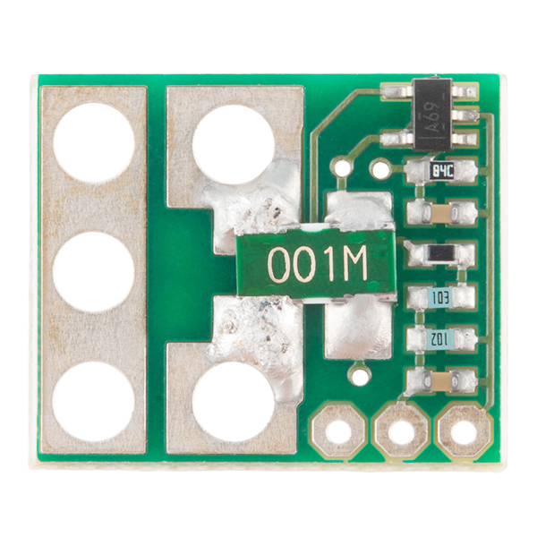
Per INA169 spec sheet (can get from Digikey website) you would change the 73.2 kOhm resistor. Updated spec/instruction sheet was sent to SFE earlier this week and confirmed received. I will also ask them to update the product photos. The 93 units in stock are 75 pieces newer PCB layout to get the INA169 IC further from the area of shunts to reduce chance of damage when soldering the leads, and slots to accept Deans Ultra connectors tweaked a bit, plus the 3 analog pins rotated to be in line with the "+ out" shunt side.
I've got this hooked up to monitor the power consumption (current & voltage) for a 12V NiMH battery system. It is connected to an Arduino MEGA 2560(5V ADC) and I am having some issues with the current sensing. Regardless of the actual current through the circuit I am reading 0V from the sensor using analogRead() and a digital multimeter. The voltage sensing is operating correctly and I have tested it in multiple setups. Are there any reasons that it would be unable to read current?
BTW, I have also found someone in a similar situation(http://talk.jeelabs.net/topic/773) but could not find a resolution. Thanks!
GeraldO,
I lost current sensing but retained voltage sensing by - I think - over-heating the INA169 chip when soldering thick cable to the non-ground input closest to the AttoPilot C&V Sensor's chip.
I suspect prevention is to use Dean's Ultra connectors per Dean's recommendation.
I have documented the problem (which I consider I created for myself) at:
http://www.kimberconsulting.com/doku.php/attopilot_current_and_voltage_sensor
Theoretically, it is possible to replace the INA169 chip... I haven't gone there. :-)
Can I use this board to measure PWM current? And how correctly to do it in this case? I tried with ACS712 board (hall effect sensor up to 5 amp) to measure value into the middle of the each pulse 100 times per second and it works fine. But measuring the same way by this board cause strange results.
For PWM, you need to have RC bandwidth of the sensor perhaps 5 multiples of the PWM frame rate, maybe more like 10-20. Think of a large ocean vessel that is several waves long... it doesn't get affected by a few waves because it always "sees" several waves across its length, and thus its attitude not affected by the waves. This current sensor has 73.2k Ohm resistor and 0.1uF cap on output of INA169 - therefore 1/(2piRC) = 0.0460 seconds, or 21.7 Hz. If the PWM frame rate is say 100 Hz or more, this sensor should be able to accurately tell the average current on 0.046 second timescales.
Dean
I erred on the bandwidth calculation. Instead of the 73.2k Ohm, you would need to know the INA169 output impedence multiplied by 0.1uF via the 1/2piRC equation.
Could I use this board to measure average voltage and current of 50kHz PWM pulses? (In my case, I use PWM to control a 24v-6.9A DC motor.) I have tried, but INA169 become overheated, flew out of board after few seconds. Thank you very much for this board.
I have a quick question on the ADC. When it says this is scaled for 3.3V ADC, what is the formula I use to convert back int a usable output? When I connect it to a 7.2V 1100mAh pack, I get 144-145, on the voltage. I'd like to code it such that I get a real Voltage indication out.
What units do you mean by "I get 144-145"? Is this a 12 bit ADC of 3.3V input range, the # of mV, or what? 7.2V sensed would cause analog out of 0.459 volts, and a 3.3V ADC at 12 bits would be 568. 10 bit at 3.3V would be 141. Sounds like you meant to say 10 bits at 3.3V range.
Read the attached spec sheet, however another way to think is 0-51.8 volts sensed is scaled to 0 to 3.3V analog out. Therfore, take the analog out voltage and multiple by 15.70, and viola you have the sensed voltage.
Dean, what I'm specifically looking for is 24/7 bi-directional current sensing - without having to disconnect and reverse the sensor in real-time.
The TI Spec sheet shows a circuit that's very close to yours, just with an additional sense chip and a couple more support components.
I've looked for simple ways of piggybacking, or dead-bug-mounting the additional components onto your board, but I didn't see any serendipitous configurations that would make it easy (or safe).
So... I'm about to start cadding one up myself out of need, but though you should have first dibs so-to-speak on the project, given the elegance and simplicity of the AttoPilot, not to mention that you have the obvious head-start with the existing design(s). More than a couple people have expressed interest already, so maybe it's something that will pan out.
If you're swamped, and if it happens to be sourced in EagleCAD, please consider me a resource if you want someone to bi-directionalize the AttoPilot for you. I'd be happy to give it my best efforts.
Dear Clint, I second the idea of a bidirectional current sensor similar to an aircraft ammeter. As in www.aircraftspruce.com/menus/in/ammeters.html My application would be a motorcycle monitor, where the bettery will at times be discharged (idle) and then again be charged (higher revs with little load). I am not nearly good enough to develop one myself, so just want to convey my support to either you or Dean to implement the circuit.
I am not attached to the AttoPilot V&I sensor as any matter of intellectual property. I consider this as a low-markup commodity to support the guidance systems. Therefore, go ahead and freely CAD up the design and modify as you wish. If you make a great little bi-directional sensor, then maybe Sparkfun will sell it for you in qty like they do with my "AttoPilot V&I" sensor. Happy CAD'ing!
Hello I am working on circuit for a school project and I was curious how you make the slot for the Deans plug in eagle?
Can I ask when these will be back in stock?
Also, when will the larger/Dean connector version be available?
Also, when will the 180Amp version be available?
180 amp version I do make as custom and involves nothing more than putting another shunt on top of each side; 4 shunts in parall total. You could go to Digikey and buy 2 (cut tape) of the shunts for about $1.48 each in low Qty, part # LVK25R001FERTR-ND (Ohmite is the maker). If SFE sees the demand, I can make both 180 and 45 amp versions as standard for their stock.
We are expecting more in by mid September.
Not sure about the Dean connector/180A version.
Answered below
Repeat of same question as I require one for a project that has a deadline of October 5th.
Thanks
I am looking to use this as an indicator for when to charge on an autonomous robotics project.
Two questions, the second probably easier: how would one use this with an MIT HandyBoard; second (more important), how would one use this with an Arduino? I just want to be able to get analog readings on voltage levels with the Arduino.
Thanks a lot!
NB
i would like to use this to test volts (30 vdc) and short circuit amps (8 Is) of a power source(s).
i guess i would need to insert a resistor or a dummy load in the circuit to be tested.
Am I on the right track? and what sort of a load would i need so as to not alter the true vdc and Is. I'm no electronics whizz obviously, so advice is paramount!
This site has been very educational already for a novice like me, thank you.
To test a dummy load - it would be a power resistor as a loop from the "+ out" back to the common GND. If supply is 30 volts and you want 8 amps current to flow, use Ohm's law as R = V/I = 30/8 = 3.75 Ohms. The dissipated power will be P = VI = 240 Watts (wow!!) or about like an entire chandelier of lights (4 x 60 watt bulbs). Note: I am not saying to to use 4 bulbs at 60 watts, because those are engineered for 120V rms AC... I am however stating that this is a LARGE shunt resistor and will take lots of cooling! Be careful.
Hello,
I can not get any measurements from the analog output pins. I tried with different voltages. 12V, 15V, 30V. Analog output ( Both V and I ) always shows zero.
I just ordered one and I think I had the same question about using a 5v adc which you just answered:
"37mA and 21mV per bit". Thanks! Can't wait till it arrives - this one is going into my son's robot.
"I want to use this device but at the 5V level, any chance someone has done the calculation for what replacement resistor would be needed?"
Can you clarify what you mean? The spec sheet talks about usage with 5V referenced ADC, and no modifications are required. You lose a small amount of resolution using 5V ADC, but the resolution is already small at 22mA / bit (12 bit ADC with 3.3Vref) and 13mV per bit. Going to 5V ADC at 12 bits, the resolution is still small at 37mA and 21mV per bit.
I'm confused about why someone would be thinking about changing resistor values on the PCB though (no offense, I am just trying to figure out motive). Changing the 73.2 kOhm resistor would change the scale factor by the INA-169 shunt monitor IC, and changing the 1k/10k/4.7k resistors would change the Vsense scale factor away from 15.7:1. In other words, you wouldn't necessarily do a specific resistor swap to make the PCB 5V specific.
Simply going to a 5V ADC allows the Vmax sensed to increase from 51.8V to > 75V, however this approach (having access to higher range) doesn't apply to the current sense because top end (~91 amps) is defined by max wattage of the two shunts (4 watts together, which happens at around 90 Amps).
If you have further questions, you can e-mail me directly at dmgoedde@gmail.com,
Dean
I want to use this device but at the 5V level, any chance someone has done the calculation for what replacement resistor would be needed?
Hi - I am Dean the creator / manuf of this board. I owe Sparkfun an updated spec sheet and instructions. The old sheet is posted to this page, but all the technical details are the same as the new board.
The notches are to take Deans Ultra connectors directly with the GND overlapping onto the large tinned area then lots of solder flooded on the entire GND area to solidly connect both leads. The notches also allow heavy gauge insulated wire to "plug in" to the sockets: stripped wire goes in small inner notch right up against the shunt leads with solder flooding it well top and bottom of PCB, and the insulation of the wire near the end can go in the larger portion of the notch.
I will provide a new spec sheet in the next 1 week.
Dean
After looking at the AttoPilot some more I realized that they just rearranged the input traces slightly to make the ground take up one end of the board. There are two notches in my board instead of the holes. The in+ and out+ wire is supposed to solder into that while the ground solders into the end of the board much like the instructions indicate.
Hi I just got mine in the mail. I plan to use these to monitor solar power generation for a project.
As soon as I opened the box I noticed that the in, ground and out traces appear to all be combined. There were no instructions. Also the board is slightly different from what is shown here even though it's the same part number (SEN-09028). Each of the inputs appear to be two small holes. The three sets of two holes are separated by large holes. Do I use a Dremel tool or similar to cut the trace where it is thinnest?
Thanks and best regards.
Will
I recommend if you want to track discharge after a charge of a battery as you described, then it would be best to re-connect the battery to the other side so that current still flows the way the circuit expects.
Dean G
Hi Dean, I meant to reply to your post so you'd get notified, but the site put my post at the end of the current posts and may not have notified you.
If you haven't already, please take a look at my post and let me know your thoughts on a true bidirectional attopilot sensor.
Thanks,
-Clint
Hi smartroad. The INA169 chip from Texas Instruments is the main holdup to 'reverse' usage of this PCB. It expects one side of the shunts to be at a higher ptoential than the other side, in other words is measures the voltage drop across a precision shunt resistor, and it assumes that one side is higher potential. I am not sure what sensed current output would appear on the "I" analog pin in this case. I have never flowed current through this board the other direction. The voltage sense portion is a lot simpler in that it's only a resistor divider. The way the circuit is layed out the resistor dividor measures the high side of the shunt relative to ground, so that any losses (however trivial) across the shunt is not degrading the voltage read directly from the DC source. If you flow current backwards the reported voltage would be just a very slight bit lower than in the forward direction (assuming something catastrophic doesn't happen to the INA169 IC and smoke it and thus mess up the entire PCB). The 'slight lower' voltage depends on how much current is flowing... at the 90 amp upper limit the V drop across the shunts (2 X 0.001 Ohm in parallel, so the combo is 0.0005 Ohms) would be only 0.045 volts. Pretty trivial voltage drop especially at lower currents.
Dean G
Hi Dean, first of all, great board!
Like others, I've found a need to monitor current going into and coming out of a battery, so I'm looking for bi-polar current monitoring. In looking at the datasheet for the INA169, they provide an example of bi-directional sensing. It requires a second INA169 and associate support components, but it really shouldn't be too hard to take your existing design and convert it to a bi-polar design. The same parallel shunts could be used.
Would you be interested in doing such a thing? Maybe if you're too busy, you'd be able to share the design files and let someone like me do the layout for you? I have a feeling many others would be interested in purchasing such a variant of your already great board.
Thanks for your consideration.
I'm also interested in a board to measure bidirectional current. Looking at the schematic, you could probably wire two of these boards in series and reverse the current in/out pins on the second board. The first would measure current in one direction, and then the second board would measure going in the reverse direction. It would be nice to have one board which output a single current reading.
I'll ask, although i prob know the answer. I'd like to use this for monitoring charge to a 12v battery, can this do 'negative' current reading? (ie read charge as well as discharge rates?)
I think it can't but want to be sure! If it can't would it just read as 0v if current is going the other way?
6s (22.2 volt nominal) is not the problem as this unit goes up to 51.8 volts if you are using a 3.3V ADC, the issue is the drawn 120 Amps.
I meant by comments to scale it up that it would have side slots to allow direct solder of Deans Ultra which are ubiquitous in the small unmanned aerial systems that use the AttoPilot autopilot system.
I also plan to make a 180 Amp version.
Whoa, careful! Read the 2nd sentence of the description above: "DC current is determined by...". Also the description in the attached spec sheet says "Compact DC Voltage and Current Sense PCB with Analog Output".
Sounds like you tried to use this on AC? Also, it should be really clear from spec sheet and "Features" section above that voltage max is 51.8 volts. Definately not 110 AC.
Disclaimer: I am the creater of this sensor re-sold through SFE.
I couldn't use this on an AC line, without modification, right? I managed to melt an extension cord connector pulling too much power through it, so yeah, I need to add some tools to watch the power draw.
Check the Spec sheet and 2nd sentence of Description above: "DC current is determined by...". No modification of this PCB for AC use is suggested, implied, etc.
Actually, you shouldn't need a giant ground lead as shown. It's only being used for a little current for sensor biasing. so a much lighter gauge wire should suffice. This would also allow the ground pad in a revised board to both shrink and move away from the power pads, reducing short circuit possibilities considerably.
Revision of board design was done a few months ago; there is not a new pending revision. However, the picture on the SFE page is outdated - check out the attached spec sheet on this page.
I use a huge GND pad because this PCB is designed for AttoPilot, specifically to have the PCB accept two Deans Ultra connectors directly, and the large GND tinned area is for solder flooding and a high current path. Selling this PCB on SFE is sort of an 'extra perk' for me.