- Home
- Product Categories
- Mux
- SparkFun Analog/Digital MUX Breakout - CD74HC4067

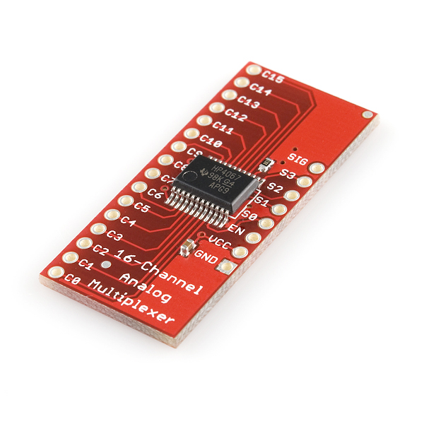
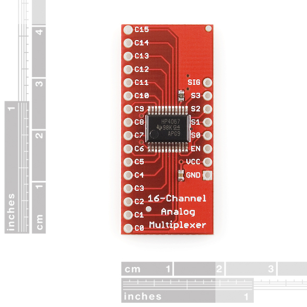
SparkFun Analog/Digital MUX Breakout - CD74HC4067
This is a breakout board for the very handy 16-Channel Analog/Digital Multiplexer/Demultiplexer CD74HC4067. This chip is like a rotary switch - it internally routes the common pin (COM in the schematic, SIG on the board) to one of 16 channel pins (CHANxx). It works with both digital and analog signals (the voltage can't be higher than VCC), and the connections function in either direction. To control it, connect 4 digital outputs to the chip's address select pins (S0-S3), and send it the binary address of the channel you want (see the datasheet for details). This allows you to connect up to 16 sensors to your system using only 5 pins!
Since the mux/demux also works with digital signals, you can use it to pipe TTL-level serial data to or from multiple devices. For example, you could use it to connect the TX pins of 16 devices to one RX pin on your microcontroller. You can then select any one of those 16 devices to listen to. If you want two-way communications, you can add a second board to route your microcontroller's TX line to 16 device's RX lines. By using multiple boards, you can create similar arrangements for I2C, SPI, etc.
The internal switches are bidirectional, support voltages between ground and VCC, have low "on" resistance and low "off" leakage, and to prevent crosstalk, perform "break-before-make" switching. The board also breaks out the chip's "enable" pin, which when driven high, will completely disconnect the common pin (all switches "off").
- 2V to 6V operation
- "On" resistance: 70 Ohms @ 4.5V
- 6ns break-before-make @ 4.5V
- Wide operating temperature range: -55C to 125C
SparkFun Analog/Digital MUX Breakout - CD74HC4067 Product Help and Resources
Core Skill: Soldering
This skill defines how difficult the soldering is on a particular product. It might be a couple simple solder joints, or require special reflow tools.
Skill Level: Rookie - The number of pins increases, and you will have to determine polarity of components and some of the components might be a bit trickier or close together. You might need solder wick or flux.
See all skill levels
Core Skill: Programming
If a board needs code or communicates somehow, you're going to need to know how to program or interface with it. The programming skill is all about communication and code.
Skill Level: Rookie - You will need a better fundamental understand of what code is, and how it works. You will be using beginner-level software and development tools like Arduino. You will be dealing directly with code, but numerous examples and libraries are available. Sensors or shields will communicate with serial or TTL.
See all skill levels
Core Skill: Electrical Prototyping
If it requires power, you need to know how much, what all the pins do, and how to hook it up. You may need to reference datasheets, schematics, and know the ins and outs of electronics.
Skill Level: Rookie - You may be required to know a bit more about the component, such as orientation, or how to hook it up, in addition to power requirements. You will need to understand polarized components.
See all skill levels
Comments
Looking for answers to technical questions?
We welcome your comments and suggestions below. However, if you are looking for solutions to technical questions please see our Technical Assistance page.
Customer Reviews
4.5 out of 5
Based on 18 ratings:
5 of 5 found this helpful:
A good product
I built a 64 channel (open ended) data logger with a logger shield/RTC, Arduino Uno 3, and 4 of these multiplexers. The operation was good. hookup was straight forward.
It is important that all inputs are fed by something. then all data reads correctly. But if inputs are left floating, the previous will carry to those floating channels. Seems the charged common circuit bleeds off previous data form other channels. ie. channel 0 is 2.35VDC. channel 1 is floating but reports 2.23VDC, channel 2 is floating but reports 2.15vdc. Unless told to do otherwise successive charge gets blead off via 70 ohms of internal resistance.
SO....(correct usage) either ground unused channels or connect them to something meaningful.
oh and... outputs can be ganged together on a single Analog input as long as only 1 channel is selected and read at a time.
4 of 4 found this helpful:
Works well!
If anyone's interested I wrote some code to read values from this mux: https://gist.github.com/nebspetrovic/125b56da1f9faa40eac2
It relies on PORTB for convenience.
1 of 1 found this helpful:
Works Slick
I was completely out of COM ports for an application that I was building on my Netduino 3. This thing saved me as it basically added 16 more ports to be available for my microcontroller; for bidirectional Tx/Rx communication you would need to use 2 chips. I adopted the code from the posted bildr article and Arduino to suit the .NET micro Framework and uploaded the source code to my github account https://github.com/JakeLardinois/NetduinoMUX.
3 of 3 found this helpful:
An excellent investment.
I haven't used the analogue features yet. But the digital part of it is great. Do note that the enable pin, EN, is active low. The description says this but I don't read...
Use this to read sixteen inputs or to control sixteen outputs (or any combination thereof) using only six pins from you micro (five pins if you hold EN low via hardwire). I used it to read buttons from a number pad.
It works perfectly!
It's a very useful device to control 16 things with 5 pins. It works perfectly fine to me!
A great value
The code is for this is available and works well. Easy to solder and wire up.
Nice little compact breakout MUX
Does what it is supposed to and the TI chip is very fast. Made it easy to integrate the TI SMT part on my THT board.
It is a very good part.
The CD74HC(T) is a great part for a little port expansion. If you are looking at multiple sensors and are not using an interrupt driven program it works well. I wish SparkFun would use FR4 circuit board material though.
It has worked perfectly!
This product has worked perfectly for my project. It is extremely easy to use and is one of the most useful breakouts I have used.
Handy I/O expanding capability
I bought this for expanding the I/o on a controller I am using within the design for an automated indoor vertical farm module. (Shout out to R2 in CT) It works okay, but I'm experiencing what appears to be a little voltage bleeding to neighboring pins. I'm a programmer and not an electronics guy, so I'm unsure if my breadboard setup is causing this or if this multiplexer isn't as shielded. So I'm still going to give it 4 stars.
All that i expected. very easy to us and understand
All that i expected. very easy to us and understand
Love these
I use these all the time because I love lots of pots and switches. Super easy to implement in any project.
Very useful
A robust little multiplexer at a great price. And no need to layout an SMD board!
Very workable
Like all of SFH products. Easy to work with & great TUTORIAL support! Def Thumbs UP!!!
Thanks Guys jimkmc
0 of 1 found this helpful:
ottimo
Qualitá ottima e spedizione veloce !! Tnx
Fast delivery, items received in good condition.
How many of these can I daisy chain?
Could have 2 gnd and 2 vcc holes to continue daisy chain for hobbyists ...
Can this be used to decode the analog signal into separate audio levels? I want to create a standalone equalizer.
Hi, maybe somebody can help me here: do i need to use pull-up resistors or any capacitor between the data lines connected to the mux and vcc line and/or the scl lines? either between my sensors and the mux or between the mux and arduino!? Thanks.
Can someone tell me what the difference is between this board and the one in the link below ? Thanks ! https://www.sparkfun.com/products/10616
is there a way to connect it to a raspberry pi 2 and read 16 analog devices ? and if yes how ?
or could i use the MCP3002 on the SIG of the CD74HC4067 and read analog on my raspberry pi 2 ?
I have a tested library that i designed. with examples https://github.com/ruralguru/ERW_CD74HC4067
Ok, I've been trying to get this to work and am failing. I can't get it to switch inputs. No matter what, I just get the input from C0. EN is set to low, and I'm pretty sure it's all wired right. Is there a need for a delay or something between switching inputs and reading that input? Does EN ever need to be set high?
I'm trying to wire this thing pretty simply to an Arduino. Are there any sample schematics or code to show how to use this?
Wrote some (untested) arduino code. http://pastebin.com/JjV1pj9m Just hook the thing up to VCC, GND, and hook up S0-3 to digital pins 2-5. No clue if it'll work yet, but eh.
How can I hook-up 8 rotary encoders with this? It sais it handles digital signals as well.
Has anyone used this for selectable output? Do the output pins have memory of what they were set to? The datasheet is kind of lacking in that info, maybe it's [un]common knowledge what I'm asking?
I'm trying to attach many simple on-off devices to an MCU but I'd like to know if I have to put in an output buffer or flip-flop or something.
What you want is a shift register: http://www.sparkfun.com/commerce/product_info.php?products_id=9519
The linked one looks like it's Parallel to Serial, but this one looks like it's going to be exactly what I need.
I got scared at "shift register" thinking I was going to cycle through all switches to turn one at the end!
4 years late but maybe someone will read this. What you really want is an "IO expander".
I had trouble with this for a little bit so I'm posting it if others want to know.
The S0-S3 act as an address so if you're measuring multiple inputs coming from the C0-C15 side you set S0-S3 to that binary pin # and read it on the SIG pin. I had assumed that a 1 on say C8 would generate a 1000 on the S lines. In this instance you have to set S to 1000 and then the value reads in on SIG.
Just for anyones info if they were having problems like I was. I didn't quite understand that from the data sheet.
What is the bandwidth of this board? Impedance?
Could this be used to switch video? What about using 5 of them to switch RGBHV(Say XGA) video?
Data sheet says 70 ohms typical. Bandwidth will be limited by the output load's capacitance. Might work for video with short cable length. It doesn't look like they sized the traces for 50 or 75 ohm impedance, but the trace lengths on this tiny board are very short so that shouldn't be an issue.
Seriously? Do you guys have any idea how much of the last two weeks I spent hand-soldering these CD74HC4067 ICs to your 28-SSOP boards with a 15w P.O.S. RadioShack iron? Clearly not, or you'd be begging to make it up to me. Is there a reason you didn't mention your intention to break these out? It's a spectacular product, but that really is too cruel. =P
I can't recommend this multiplexer highly enough. Love you guys ;-) Keep up the good work!
Thanks Zerk! We're building them as quick as we can. We never gauge new product demand correctly, but our production dept usually catches up within a week or so.
Why not use the DIP version? Is the DIP version not available?
Good question - both TI and NXP make a DIP version available from Mouser and Digikey. This was created for a friend who needed to solidly connect a bunch of sensors to his Arduino and didn't want to add a breadboard to his setup.
The eagle files show a pair of standoff holes on this, but the pictures don't. Does it have standoffs or not?
Hi,
I want to use this board to send pwm outputs and read analog inputs. Is this possible? for example 10 pwm outputs + 6 analog inputs = I have read a few the bildr tutorial and it talks about using this multiplexer for sending 16 pwm outputs or reading 16 analog inputs but not both.
Is this possible? Thanks!
Hi, is this board able to drive multiple I2C sensor, that has the same address, on a single channel?
I would like to hook up to an Arduino, 8 IMU-6050; but the chip uses only 2 address for the I2C channel; so I am looking for a mux that can do the job. Is this one able to do so? And if it is the right tool for the right job; is there any example code to learn how to probe each sensor at specified interval? Thanks!
No wonder I cant get my keypad to talk to my Arduino. I thought the enable pin was active HIGH based on the silkscreen. It really nees that little bar above "EN" to denote this.
Does anyone know if there is a fritzing part for this? I could not find one and would like to include in my breadboard view.
Will this board allow me to get analog readings from an analog sensor? For example, if I'm using a Force Sensitive Resistor (like this https://www.sparkfun.com/products/9375), can I get a value from 0-1023? I initially started using a different chip (the MCP23017), but quickly learned that, while it says it is for analog and digital inputs/outputs, it can only return digital readings -- so I'm only getting a 0 or 1 from the Force Sensitive Resistor.
Ive used this and it works well, although could't I connect 6 of these, tie all 6 S0 together, same as S1, S2 and S3, then tie each SIG to a channel to another mux breakout, so in theory I could control 80 inputs/outputs only using 9 pins? I only ask because I've checked out the MUX Breakout II but I haven't dissected it yet but it looks like they have incorporated 6 shift registers, wouldn't it just be easier, smaller, cheaper and more powerful to just use another CD74HC4067 to talk to up to 16 other CD74HC4067s?
Of course I am not planning on reading potentiometers, it would slow down tremendously, but rather read the state of latching switches.
Can I use this board without any other device? Can I send it commands directly from a serial port? I would like to use it as a low cost analog video switch. My programming environment is VB.Net...
No serial alone wont work, but you could easily use something like the arduino pro "micro" to communicate with visual basic via serial, then simply send commands to the mcu to control the mux board, and to make it more cost effective just design your own pcb incorporating the CD74HC4067 and get the pcb printed from OSH Park, total cost would be under 18 bucks, or even cheaper, search around amazon lol
my guess is NO ...but im going to ask anyway! is there anyway to use C0-C7 as analog inputs & C8-C15 as digital outputs at the same time? basically im wanting to read 8 pots in sequence and light an indicator LED so you know which pot is active. would be great if i can utilize those extra 8 pins on this board instead of having to use a shift register chip for the leds :)
Thanks..
Could I use this to multiplex LED's with enough precision to control brightness? (or rather transistors driving high powered leds)
Schematic is wierd :(
It looks "wierd" to me too, we'll get it fixed. Thanks!
While I might have drawn it differently (first thing would have been moving the internals of the chip around and probably mirror the entire thing), in what way is it weird?
I think i already know the answer to this, but...
Let's say I have a matrix keyboard, where connecting line X0 with line Y0 results in a keypress. Pretty standard part.
I connect all the rows/columns, one each to a pin on this or similar multiplexing chip. Is there any way, with one chip, to connect those pins to each other?
I figure I can do it with two mux ICs, one for columns, one for rows, joined at their common I/O pin, but I'm trying to save room and parts by trying to combine that into one chip. If not this one, then maybe someone can recommend one? I need an 8x10 matrix.
Can this be used to control a 7 segment display? Or would it be better to use 2 shift registers? I think the main question is about the you can switch the digital writes on this.
Hi, I want to use this board for connecting multiple micros to one master micro using serial pins (tx/rx). One board for each signal, will this work ?
You got it! One board for all the TX lines, and one board for the RX lines will work. Just make sure you match your logic levels.
Ok... Have I been going about this all wrong? When using this chip to read multiple sensors (switches) I have been pulling each of the 16 inputs low with a resistor (one for each pin) which is a total mess, especially when piggybacking this on a protoshield (leaves no space for... anything else.) and then something donned on me: Can I just use 1 resistor to pull the SIG pin low and let the switches float? This would save a lot of time, space, and resistors!
Would anyone know how to wire this to a clock so it cycles automatically?
Can you connect this in a similar fashion to the 4051? http://tomekness.files.wordpress.com/2007/02/analog_multiplexer_demultiplexer_4051.pdf
If you are asking if this connects in a similar fashion as the 4051 then, the answer is yes. This is the big brother to the 4051.
So in theory then, I could have one connected to the arduino with 16 chained underneath it? Similarly to how the example I shared does for the 4051. This indeed makes me happy.
How do you use this with SPI? Don't see anything in the datasheet about how to connect this..
It doesn't use SPI. It has four digital inputs (S0-S3), that you drive with the binary number of the input pin you want to route to the output pin. 0000 = input 0, 0001 = input 1, 0010 = input 2, etc. (0 is a LOW input, 1 is a HIGH input.)
Right, thanks! I read the description a little bit too fast..
what are the two surface mount components on break out board ?
are they by decoupling capacitors ?
One is a pulldown resistor on
EN. The other is a .1uF capacitor.Look at the schematic for more information.
Bought one of these recently and ity works great with 16 outputs. Is there any way of using a second Mux (with an Arduino) to get 32 outputs?
These boards can share most of their pins. They can't share
ENpins though.Why not just buy it in a DIP package?
would this work for demuxing a DAC? in other words, if i connect my dac out pin from the ARDUINO to this, could i get 16 channels out? is there code for using this thing?
thanks
so im building a project that needs a x/y axis servos plus another one for a trigger would this work for that if not what would also to connect Spring Terminals to this and adding some sensors to this like a pir and making my arduino IR capable so i can use remote and a lcd and a separate touch screen to this. Would this work with the msp430g2 launchpad? and how would i connect this to eather the arduino uno and the msp430 launchpad
basicly i need it to control some sensors and 3 servos will this work and wat board will it fit arduino uno or the msp430 launchpad or both
Can this be used to send audio from a computer headphone output directly?
Does this come with the CD74HC4067 or is that to be soldered onto the board by the buyer?
I am doing a ADC/DAC mux for analog voltage range of +5V to -5V. This device has single supply Vcc=2-6V.<br />
Can it be used for +/-5V analog voltage range with single supply? Thanks.
The schematic does not match the labels on the actual board. What is up with that? Which is correct?
So I want to connect 16 push buttons to a arduino nano using this shield in such a way it would read simultaneous presses. Can This be used to MUX the digital inputs on the arduino or do I have to wire resistors up to the buttons and go via analog??
Just made a sketchup model for this as well as putting together a group for various components found on this site. <br />
http://sketchup.google.com/3dwarehouse/details?mid=f1b5beed30be925d7b60bd1235096291&prevstart=0<br />
<br />
http://sketchup.google.com/3dwarehouse/cldetails?mid=479cab9a5e32efc37b60bd1235096291&ct=mdcc&prevstart=0
is it necessary to tie unused inputs on this MUX to ground?
Yes you have to plug any unused channel selector IO pin to ground.
can you do analog and digital at the same time on this board?. ... like if i wanted to split it up as 8 digital and 8 analog inputs?
Sure, just keep in mind that all the I/O are muxed to a single O/I pin, so make sure that pin can handle either source type.
Is there some reason that this board doesn't have mounting holes? It would make it just a little more convenient and look neater then when I am going to have to put them in.
Would this work for piezo's on an arduino based electric drum set? I need more analog inputs than just 6 and can't afford a arduino mega.
Yes, I used a multiplexer to get sensor readings from multiple piezos
Be careful and inspect your boards when you get them. I spent a good few hours debugging what I thought was a flaw in my looping algorithm when it turned out that two of the legs on the MUX chip were just barely soldered together causing one of the digital pins always to return a 0. All it took was a little bit of scraping with an exacto knife, but it took hours to track down.
silvap: Cant this multiplexer board drive servos?
* i mean "can" instead of "cant"
Can this multiplexer board drive servos?
Cant this multiplexer board drive servos?
No, it would not be able to drive multiple servos. This is used to connect 16 analogue sources to one A/D pin. Besides, servos need constant attention with their signal to work properly. You can use something like the Serial Servo Controller or convert some servos with the OpenServo boards and control them all with two lines with I2C.
I can be dense at times, but after reading the datasheet I'm still scratching my head....Is there any tutorial on how to actually wire this up to your MCU? (preferably a mega8/168/328)
In case anyone is looking, here's a really simple diagram for hooking this up.
Haven't played with mine yet but I believe you connect pin 1 to your analog input pin and then connect 10,11,13,14 (S0-S3 in the data sheet) to digital outs, and then use them to select which of the 16 input pins is passed to your mcu. Use page 2 of the data sheet to see how to select pins.