- Home
- Product Categories
- Level Shifters
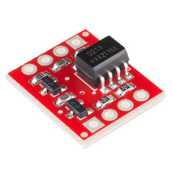
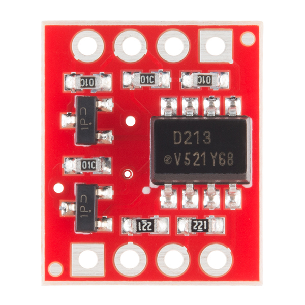
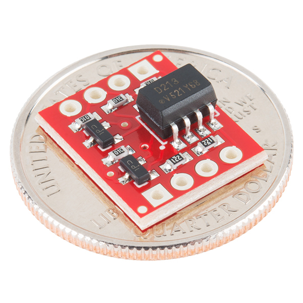
- SparkFun Opto-isolator Breakout

SparkFun Opto-isolator Breakout
This is a board designed for opto-isolation. This board is helpful for connecting digital systems (like a 5V microcontroller) to a high-voltage or noisy system. This board electrically isolates a controller from the high-power system by use of an opto-isolator IC. This IC has two LEDs and two photodiodes built-in. This allows the low-voltage side to control a high voltage side.
We often use this board to allow a microcontroller control servos or other motors that use a higher voltage than the TTL logic on the (3.3V or 5V) micro, and may cause electromagnetic interferance with our system as the motors turn on and off. This board will isolate the systems, creating a type of electrical noise barrier between devices.
This breakout board uses the ILD213T optoisolator and discrete transistors to correct the logic. Comes with two channels. Great for use in noisy circuits where signal lines require electrical isolation.
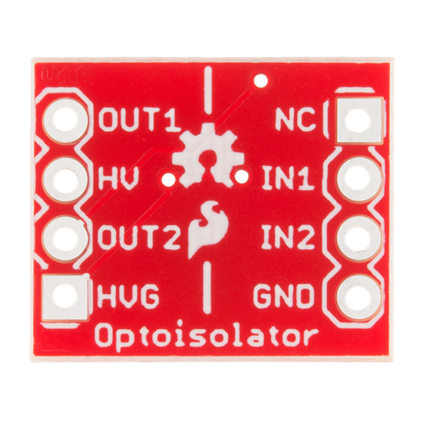
A normal LED opto-isolator will invert the logic of a signal. We threw some transistors on this compact board to correct the inversion. What you put into the IN pins, will be replicated on the the OUT pins, but at the higher voltage (HV). This optoisolator is configured for data rates up to 9600bps. For MIDI applications (31250bps) consider our MIDI Arduino Shield.
- Schematic
- Eagle Files
- Datasheet (ILD213T)
- GitHub
SparkFun Opto-isolator Breakout Product Help and Resources
Core Skill: Soldering
This skill defines how difficult the soldering is on a particular product. It might be a couple simple solder joints, or require special reflow tools.
Skill Level: Noob - Some basic soldering is required, but it is limited to a just a few pins, basic through-hole soldering, and couple (if any) polarized components. A basic soldering iron is all you should need.
See all skill levels
Core Skill: Programming
If a board needs code or communicates somehow, you're going to need to know how to program or interface with it. The programming skill is all about communication and code.
Skill Level: Rookie - You will need a better fundamental understand of what code is, and how it works. You will be using beginner-level software and development tools like Arduino. You will be dealing directly with code, but numerous examples and libraries are available. Sensors or shields will communicate with serial or TTL.
See all skill levels
Core Skill: Electrical Prototyping
If it requires power, you need to know how much, what all the pins do, and how to hook it up. You may need to reference datasheets, schematics, and know the ins and outs of electronics.
Skill Level: Rookie - You may be required to know a bit more about the component, such as orientation, or how to hook it up, in addition to power requirements. You will need to understand polarized components.
See all skill levels
Comments
Looking for answers to technical questions?
We welcome your comments and suggestions below. However, if you are looking for solutions to technical questions please see our Technical Assistance page.
Customer Reviews
4.4 out of 5
Based on 14 ratings:
2 of 2 found this helpful:
Great for what it is - Description is slightly misleading
For logic level voltage conversions and isolating two circuits, this is perfect, which is good, because that's what it was designed for.
The description and instructions are lacking bits of info that are imperative for first time users to understand (I'm a first time user and didn't understand these things).
The "high voltage" side of the opto-isolator is not designed to have your main "high current" circuit ran directly through it. You wont get the amperage you need out of it. This is easily overcome by using the opto-isolator to drive a FET that controls your "high current" circuit.
If you are using the opto-isolator to step down in voltage (i.e. reading a 12v limit switch circuit with a 5v Arduino) you will need to put a resistor in line with your Inputs so as not to fry the LEDs inside (they are designed for a 5v circuit). You will need to do some math to determine the correct resistor size.
1 of 1 found this helpful:
Worked like a champ!
Had severe noise problem when connecting the external trigger lines of three separate data acquisition systems to a common trigger source. The noise varied from a 3 to 5 volt sine wave causing the DAQ's to trigger. Hooked this little guy between the trigger source and the external trigger inputs and cleaned everything up. The noise was caused by ground loops. Couldn't have completed the experiments without it. Also I measured the delay to be only 4 microseconds.
1 of 1 found this helpful:
Easy to use for signal conversion - High (24vdc) to Low (5vdc)
I had two 24vdc inputs and needed to switch two 5VDC logic signals. This board worked perfectly. I did have to add some resistance on the front end as to not burn out the optos, but 1k ohms later and I was off and running.
6 of 7 found this helpful:
Works well, expect for fast serial data
The 10k load resistors on the "output side" mean the switching time of the optocoupled transistors are close to 100 us, which means baud rates above 9600 will not work. This means the breakout is useless for a MIDI application (which is optoisolated transmission at 31250 baud serial). So good for isolation, not for fast signalling.
1 of 2 found this helpful:
Great for prototyping
I needed to monitor and emulate marine pump alarms with a +3.3V microcontroller. I just added the 1.5K ohm resistors in series and everything worked as planned. I was able to sense the 12V alarms and and forward serialized data to a system monitor with ease.
Great board for isolation
I'm using four of thees in Gecko G320x servo drive reset circuits driven by a Pokeys57CNC board and they work perfectly.
Works great
Works great, but just a heads up to anyone using the sparkfun eagle library the pins (5,6) and (7,8) are transposed in the symbol.
https://github.com/sparkfun/SparkFun-Eagle-Libraries/issues/153
Good for isolating inputs, too
The documentation describes how to use the device to isolate a controller's outputs from the device being controlled. But it works equally well to protect inputs.
Works well
Used to opto-isolate my arduino from a stepper motor, fairly straight forward to solder posts to it and use.
Great little breakout
This friendo did an excellent job of separating my PWM fan voltage from my microcontroller board and I've got a few more around for any other uses that spring up.
a nice little board
the board is small,so soldering by hand takes care. I put mounting pins on the opto board and then soldered to the main board-- this was effective
Works great
Made connecting up the noisy side from the clean (ardunio) side easy.
PWM functionality unknown
It works great for Digital IO but I have been trying to use a PWM with it. And I get nothing on the output even at 10 hertz. 50% duty cycle.
Has anyone attempted to use it with a PWM? any luck?
Works
I'm using this to convert the 5v logic signals from encoders on my tool turret to 24v inputs into my Mesa card. It is currently hanging on it's wires, since I haven't figured out how to mount it.
-------------------- Tech Support Tips/Troubleshooting/Common Issues --------------------
Optocoupler vs Opto-isolator
Difference between optocoupler and opto-isolator http://www.electronicproducts.com/Optoelectronics/Optocouplers_and_Optoisolators/Optocoupler_vs_optoisolator.aspx.
Opto-Isolator with I2C?
I have not tested the opto-isolator breakout with I2C before. I2C is very sensitive with its connection and timing so it might not work by connecting two I2C devices together. Based on the theory of I2C [ https://learn.sparkfun.com/tutorials/i2c#why-use-i2c ], I do not think that it will work by just placing the opto-isolator between the two I2C devices since the opto-isolator is uni-directional.
Try looking at this app note for opto-isolating the I2C bus http://dangerousprototypes.com/blog/2012/01/15/app-note-opto-isolating-the-i2c-bus/
can i use this to separate arduino from esc motor controller? esc has a servo interface, running on different voltage than arduino. will it control the esc?
can IN1 and IN2 be 20V and HV be 3.3V ?
No. For more details, refer to the datasheet linked under the Documents tab.
Does anyone know if this would work well for driving automotive relays?
Should work fine. We use a similar part (single channel) on our Qwiic Relay boards.
Will this work for UART transmission in both directions?
Hi,
i want to use this to isolate a camera trigger switch for remote shutter release. Can it safely isolate the signal from Arduino to the camera? How do i wire this component?
Thanks Markus
Could I control APA102 Leds with those? Feed data and clock line through it
I am confused by the schematic for the Optoisolator-V12. I assume the board needs power to operate. With this in mind, what is the voltage input? Does the voltage input go to "HV?"
Thanks Bret C
nm. I'm an idiot.
I understand that Sparkfun has to keep these boards small to remain price competitive.
However, how high can the rated isolation voltage be on this board when the "high side" and "logic side" components are so close together? Protected voltage ratings depend on distance and other types of barriers, this board seems to deliver neither in great quantity.
Hence, you may want to be very clear with your user base that the ILD213T will have a much higher isolation rating than this board design allows, hence advise your users not to use this opto-coupler board in high-voltage applications. FWIW, the junk sold on ebay is no better... 2.5kV-rated chips coupled with (maybe!) 100V-resistant board designs.
Can you please add the specs for the output transistors? Specifically, what are their voltage and current ratings?
Good question: MMBT2222. 40V/600mA. I think this is the part # : MMBT2222ALT3G.
It would be great if this board were rotationally symmetric so that it could be used for inputs or outputs just by flipping the board around. You could leave the output/HV side as is and rearrange the input side as follows:
Pin 1 (currently the NC square pad) becomes GND, Pin 2 (currentyl IN1) becomes IN2, Pin 3 (currently IN2) is NC, Pin 4 (currently GND) is the new IN1.
This lines up the mappings with the output/HV side so if you rotate the board 180 degrees, the signals and grounds line up on the same pins.
Please post data sheets for the transistors on this board, or at least identify them! Thanks.
Can I power a 12 volt 500 ma solenoid coil with this opto-isolator board? I broke out both my voltages from an 8 AA cell battery pack. I'm using 3 volts on the input side (2 AA's), and 12 volts for the solenoid (8AA's). My input supply side signal is an analog output from a 3.0 volt ATmega328 chip (output A0 ). I have the output side on 12 volts to drive the solenoid coil. I don't want to fry the output pin of the atmega. If I add a 12 volt relay before the solenoid coil, will that help? Or is this board made to replace that also? I can also add a clamping diode on the solenoid coil if needed.
how come there are not mounting holes so you don't have to float the device in the air and can fasten it down to a chassis.
PCB material is surprisingly expensive, so for small boards that are likely to be plugged into a breadboard, we try to keep the price down by not adding mounting holes. People will often secure them with epoxy, hot glue, double-sided foam tape, etc.
[3M 4956 VHB acrylic tape](http://solutions.3m.com/wps/portal/3M/en_US/Marine/Home/Products/Catalog/?PC_Z7_RJH9U5230GE3E02LECIE20S4K7000000_nid=R7SCJ241XDbeN4BX5SJJFCgl http://www.uline.com/BL_6046/3M-4956-VHB-Acrylic-Foam-Tape) is very good at permanently holding a PCB down, even over industrial temperature range. It is much better than typical foam tape which can fall off in hot humid weather. (which can destroy expensive equipment)
Just keep in mind, once you stick it down, it is very difficult to get it off. For this small PCB, the easiest way to get the tape off if you use a singe piece, is to twist the PCB. If you mount a larger PCB in 4 corners, you would will need some kind of wooden dowel with a flat edge like a screwdriver to remove the tape.
While the length of the tape rolls are on the long side, this would be a good product for Sparkfun to carry, since it has many uses.
Will this board work in conjuction with the Atto Pilot current sensor? I want to be able to measure current and voltage without getting unwanted noise from the power supply. The Atto Pilot worked brilliantly with a 24V/3A DC power supply but when I went to a higher voltage and current power supply the sensor was unable to give correct readings and would crash the program every time I went to turn on the power supply or raise the voltage. I'm guessing that this was due to the noise created when the power supply turned on as I was able to connect the leads after the power supply was turned on and get readings. In doing this I ended up frying a chip on the Atto Pilot sensor and am unable to read current anymore.
I'm thinking this optoisolator would need to go between the Atto Pilot sensor and the Arduino in order to filter out the noise that causes my program to crash. Is this true?
Could this be used to sense whether there is voltage on the high-volt side from a microcontroller? I have read that you could use an optocoupler or isolator to do it, but the labels on the pins make me beleive that this works in only one direction, from low-volt to high-volt. Anyways, you guys double-rock!!!
The problem with correcting the inversion is that if you're using this board to run relays and you connect one side of the coil to HV and the other side to the outputs of this board, the relays will always turn on when the power is switched on. This is a Bad Thing™ because it doesn't fail safe.
I cannot think of a way to run this in a safe way with this board, since the 10k pullup resistors won't supply enough power to run the coil of a relay.
Can anyone think of a solution? I'm a little stuck currently!
Would 5.5V be too much for IN1 and IN2?
I'm trying to use this with a Fez Panda 2 to activate an RC Car ESC. The feed from the ESC is 7.6v which is connected to HV. HV_GND is connected to the ground wire from the servo plug. The 'on' wire, which is normally shorted to the power feed by the on switch (now disconnected) is connected to OUT1.
I have tried IN1 connected to one on the digital outputs, the regulated 5v pin, and the Vin pin (separately) but OUT1 is only about 1.6v when IN1 is high. (It's 0v when IN1 is low).
Any ideas what I'm missing?
Thanks in advance.
I want to use this to isolate a camera trigger switch for remote shutter release. Can it safely isolate the signal from Arduino to the camera?
Is this possible to drive a small fan (5V / 200 mA) directly with this board ? (according to Nate, seems that the output transistors are 40V/600mA)
No! It is useless Breakout because it CAN'T directly drive anything . The only way to use it - use as isolated logic output to switch transistor.
I (noob) need help figuring out how to wire this thing.
I'm connecting the GND to netduino's GND, IN1 to netduino's 3V .
For the noisy side I need to drive a small motor but for now I'm using a light bulb just to see the result. Output is connected like this: HVG to battery's one side, HV to the other side of the battery (I tried switching battery poles but still no success) and I expect the voltage between HVG or HV and OUT1 to change when I plug/unplug IN1 from 3V but I don't get either result, the bulb remains dark and the multimeter doesn't show anything changing.
Pls help
nvm I figured it out.
Is this right
IN1 & 2 - From my Arduino Uno
NC - ???
GND - ground of some kind
OUT1 & 2 - To my door lock power +/-
HV and HVG - I take it thats where I wire my 12v power supply to power my Door Lock...
Sorry i'm rather unsure how to do this...
I would actually like to see a combined version of this BoB and the 10256 BoB. Two channel would be a good start but four channel would be very handy. Uses would be for running 12 volt automotive lamps/devices from a noisy 12 volt power source. With opto isolation I would think the microcontroller would handle PWM or basic digital control flawlessly. Just be sure not to tie any grounds together or better yet, have a user configurable ground strap.
I bought this thinking I could use it to trigger a flash or a camera using arduino. all I need is to short the leads of the sync cable or camera remote cable.
Can this board be used for that? how do I wire it?
Any help would be appreciated
This seems geared for output isolation, what is offered for input isolation? Needing something multi channel to feed into 3.3V (5V tolerant) inputs on an Arm Cortex.
Hi, I'm a novice in electronics. I've supplied 3.3V to IN1 and 5.0V to HV. GND and HVG are common and I read 4.4V at OUT1 and 0V at OUT2.
I know I'm not wiring this correctly (when I remove the 3.3V, the 4.4V remains....) The schematic is unclear to me, can someone please help?
Nevermind, I figured it out.
Why is this board using a NPN transistor in common emitter configuration? With the 10K resistor, this board will only output around 1mA at 12 volts.
A PNP transistor will allow this board to drive a higher current load (up to the max Ic of the transistor) such as relays and motors.
Help! I connected the optoisolator to a ringer detection circuit which puts 2.3V across the input, but it doesn't switch. HV line is 5V. Are these values too small?
Connecting the two opto emitters together under the chip was a dirty-rotten thing to do. A simple breakout for the opto would be better suited for my purpose (and more universal). The open-collector configuration is not suitable for many applications.
Sorry! We can't please everyone. You can always desolder components if you still need the breakout.
Turns out I didn't need to float the IC to separate the collectors (that would have been obvious had the board layout been available). Anyways I put the thing to use, after modifications, and it is now in service happily isolating a PWM signal feeding an integrating circuit. Voila! Isolated 0-10V DAC. :-)
Did you use this to control a dimmer that runs off of 0-10V analog?
The schematic is listed above and all of our Eagle files are available if you email us and request it. In the future you can contact us directly (techsupport@sparkfun.com) and we can provide the Eagle files.
I meant the emitters. Long night...
One possible future iteration of this board could include an optoisolator with a bit more max amperage ability. Examples I've played with include the HCPL-3120 and the FOD3120 (which can both max out at 2.5 A). These can provide a very simple way to hook up a micro to a high voltage and/or current-demanding motor. If you don't need a "smart" motor driver, those chips work very well!
if you pmw the input, then yes up to 40V DC
will this allow me to dim lights?
if you pmw the input, then yes
This should work for a serial connection between my robot noisy motors and my sensor array that uses 4 sharp infared sensors right? . . im only using 9600 baud? . i need a way to isolate the two . and i dont mind using seperate power sources.
I gave this a try with a 3.3V Arduino Pro Mini. I could reliably transmit serial data at up to 14400 baud. 19200 and above didn't work, though.
The 4 Channel Optoisolator DIP worked a bit better -- all the way up to 57600 baud, but it requires a couple external resistors to get set up.
Use a max232 or st232. Need a max232 + 5 0.1uF caps at each end.
No problems with 9600 or 115200.
Work fine with most micros that run at 5v and have 5v io or via a level shifter for boards like gumstix overo, beagleboard or anything else that uses 1.8V or 3.3V io.
For a level shifter http://www.sparkfun.com/products/8745
just note the 10k pull ups on the output of the tx on the high side.
The switching time of the ILD213T means it is NOT suitable for isolation of a serial port at higher baud rates though; if I'm reading the data sheet correctly, the turn-on time is ~100uS and turn-off is about 30uS with the 10K resistor. It definitely DOESN'T work at 115200 baud!
I would also like to use this breakout for isolating a 9600 baud serial connection.
I was thinking about replacing the 10k resisters with 100 ohm resisters in order to reduce the on/off times. What do you think?
to answer my own question.. yes ..at 4800 baud
Could this controll switching of EL wire? 200v DC at .05 amps?
Not without connecting it to a triac or relay.
I was looking for a way an FPGA can turn on and off 12volt stuff, like headlight bulbs and the siren off a dead alarm, do you think will do that?
I think it makes a fun project more fun to try to interface some on hand items like that.
Use this (or similar):
http://www.sparkfun.com/products/10256
You could have avoided the extra transistors by arranging the output transistors in the optocoupler to pull the line UP to "HV" and using pull-down resistors to pull the line DOWN to "HV_GND". This assumes that the circuit this is connected to could tolerate the relatively weak pull down of a resistor instead of a transistor pull-down.