- Home
- Product Categories
- XBee Boards
- SparkFun XBee Explorer Regulated

SparkFun XBee Explorer Regulated
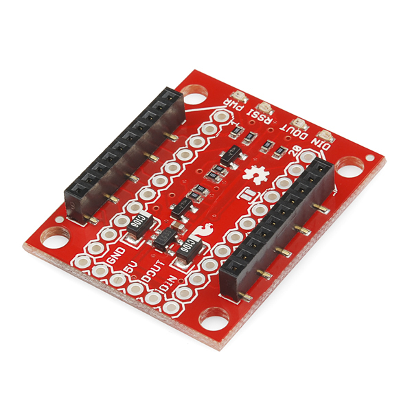
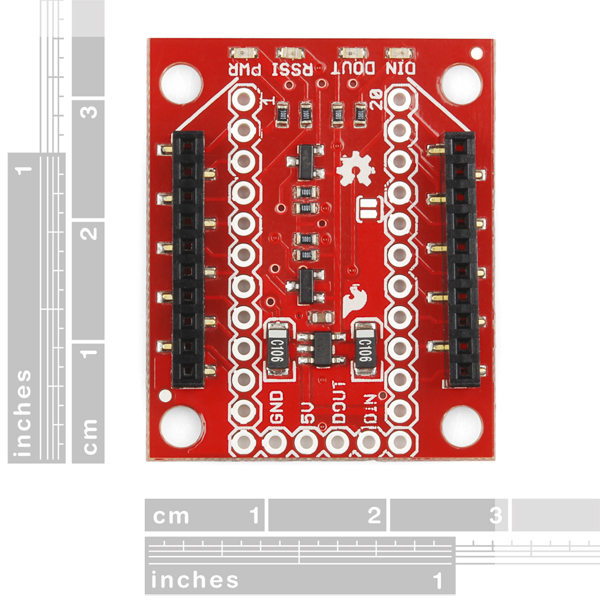
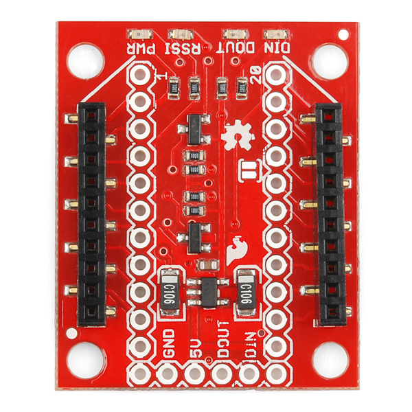
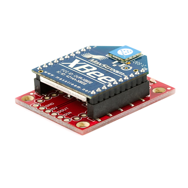
The SparkFun XBee Explorer Regulated takes care of the 3.3V regulation, signal conditioning, and basic activity indicators (Power, RSSI and DIN/DOUT activity LEDs). It translates the 5V serial signals to 3.3V so that you can connect a 5V (down to 3.3V) system to any XBee module. The board was conveniently designed to mate directly with the SparkFun Arduino Pro series of boards for wireless bootloading and USB based configuration.
This unit works with all XBee modules including the Series 1 and 2, standard and Pro versions. Plug an XBee into this breakout and you will have direct access to the serial and programming pins on the XBee unit and will be able to power the XBee with 5V.
This board comes fully populated with 3.3V regulator (5V max input), XBee socket, four status LEDs, and level shifting. In the latest revision the diode level shifter is replaced with a more robust MOSFET level shifter. This board does not include and XBee module. XBee modules sold below.
Note: This board cannot source the power required for the Cellular XBee line. It will only work with the 802.15.4 variants.
Need a custom board? This component can be found in SparkFun's À La Carte board builder. You can have a custom design fabricated with this component - and your choice of hundreds of other sensors, actuators and wireless devices - delivered to you in just a few weeks.

SparkFun XBee Explorer Regulated Product Help and Resources
Simon Splosion Wireless
February 13, 2014
This is a tutorial demonstrating one of many techniques to "hack" the Simon Says. We will highlight the technique to take your Simon Says Wireless.
Wireless Joystick Hookup Guide
January 5, 2017
A hookup guide for the SparkFun Wireless Joystick Kit.
Core Skill: Soldering
This skill defines how difficult the soldering is on a particular product. It might be a couple simple solder joints, or require special reflow tools.
Skill Level: Noob - Some basic soldering is required, but it is limited to a just a few pins, basic through-hole soldering, and couple (if any) polarized components. A basic soldering iron is all you should need.
See all skill levels
Comments
Looking for answers to technical questions?
We welcome your comments and suggestions below. However, if you are looking for solutions to technical questions please see our Technical Assistance page.
Customer Reviews
4.4 out of 5
Based on 19 ratings:
1 of 1 found this helpful:
Grate board
Being fom the caribben and ordering stuff from the us is somtimes a nightmare because you sometimes get faulty, broken and damage goods. Sometimes dont get the goods at all. And there is nothing we can do about it because we are not in the us. But this is not the case with the stuff i have gotten from Sparkfun. Grate explorer boad With a little time putting the board together you end up with a wonderful pice of tool. Notice that i said tool, because to me its not just a board. Five staRs for me.
1 of 1 found this helpful:
For the purpose for which I bought 2 of these -- for connecting XBee Pro 900HP modules in a near-Earth object balloon project -- they are not much use.
Xbee doesn't well-document the setup I have (XBee -> Explorer -> FTDI -> USB cable -> MacBook), and I've not yet been able to actually use XBees in this setup due to odd, undocumented behaviour. It's not possible to flash XBees in this setup due to unresolvable errors, and I've even managed to brick one of the XBees trying to get it to work.
If you go with this setup, make sure you're going down a well-defined path, and be prepared for frustration and lots of Googling.
Sorry to hear about the issues with the explorer breakout.
Have you contacted our support department @ techsupport@sparkfun.com ? They're usually really good at addressing issues in setups like this.
7 of 7 found this helpful:
Works
Like the Parallax version of the Explorer, the pin numbers are wired in a way that is most confusing. It is off by one on one side and off by one in a different direction on the other side. All instructions including those written by Sparkfun go by XBee pin number, not Explorer pin number. You couldn't make it more confusing if you tried. The least you could do if you ever decide to change it in any way is make it more clear where pin 1 is.
1 of 2 found this helpful:
I own a number of these and they work great
It works as advertised and I've never had an issue
very well made
The explorer is well made, I was able to easily solder to the pins that I needed and the mounting holes are slightly larger than other boards, so mounting was easy also.
Great Gadget!
These are great for fitting ab XBee into a verry small spot, and for running an XBee off Arduino serial ports OTHER than serial0 like all the shield makers want us to do. I prefer to keep Serial0 for updating programs (via USB), and use Serial1 for my comms work. I also found that I can still get at the direct signal ports (I'm using pins 19 & 20 via level changers) for signals in addition to my communications protocol via Din and Dout (which are already buffered). I also love the LEDs on Din and Dout, it makes it easy to debug.
works perfectly
no problems with it
Ordered 4 - all not working
I received 4 of these.. and have had zero luck getting XCTU to recognize the Xbee's I've plugged into them (yes, the correct way ;))
Tried via arduino and ftdi cable. No joy. Power light is on; that's about it. Tried every guide/idea I could find on the net - no luck. RST to GND does nothing. Either the Xbees I got were all DOA, or these boards (or both) - either way I am super disappointed and going to push to return the lot.
Update: Although I still can't configure it directly using an Arduino (which you should be able to do) I was able to finally get XCTU to see it with the FTDI cable after I soldered additional RTS & CTS lines. Once configured though, you should only need gnd, 5v, tx and rx from an arduino to this board. Will report back if that works.
Sorry you are having problems. This board is designed to mate with a Pro Mini meaning the RX/TX are reversed from what they are on an FTDI board/cable. Make sure you have RX going to TX and TX going to RX. If that doesn't work please contact our technical support team and they can help you or work with you on a return.
Xbee Explorer makes it easy
couldn't be simpler. Having the 3.3Vreg on board for the XBee and being able to power the board from +5V makes it dirt simple to implement. I was able to 3D print a nice small box allowing it to sit proud of the body of my Hexapod so the carbon fiber body would not interfere with the signal. love it
Works
My only complaint is that when setting the xbee s6 on the board it covers the pin connections on the left. Had to bend connection pins to 90 degress to get it to fit.
Great little board
I am particularly happy with the voltage level shifting (most of my circuits run on 5VDC) and the standardized pin spacing. The easy access to 5V,Gnd,DIN and DOUT are also very handy. I am using several of these great little boards.
allowed me to complete an important project
I needed to install a remote status reporting device that used a tiny TCP server that is interrogated with socket communication from a desktop computer. This board fits the profile of this particular device perfectly. I have also used it with XBee products as well. It converts incoming 5 VDC power to the 3.3 volts needed by the devices.
Convenient and compact
Also, fast delivery and brilliant service!
Can't use an XBee without it.
Four wires to an Arduino pro mini and my radio control transmitter was mostly done. It has a regulator and will run the XBee from the same 5V power supply as the Arduino. Used an old Futaba RC transmitter for the housing. trigger and steering wheel controls, and use it to control a robot that has another XBee explorer connected to an Arduino Mega.
love the low power consumption
I have been using this item for several years for amateur rocket telemetry. The XBee has to be high power and sit for as long as several hours. My 1s 1300mAHr LiPO will send me a 250mw signal every second for 1 hour per 100mv battery drop (10 hours or more). I have had no 3.3v regulator that combined with the radio for that level of performance, never mind the compact footprint of the explorer.
Working as expected
Working as expected :-)
Easy to Use
Used with a ublox gps, it just works.
Didn't have any need to dig into how.
Excellent break-out
Headers are a little weird, but the design facilitates the ability to breadboard this thing in two different configurations. wish it was just a little more narrow so it wouldn't eat up the entire breadboard width.
Anyone have the part number for the female header the Xbee plugs into? I need to replace one.
Yep, it's PRT-10030!
I'm trying to attach this board to the LiPo Charger: PRT-14411 even without batter with direct connection to USB the consumption of the Charger is about 2mA. When I plug the empty WRL-11373 without XBee attached, I got: 1. Current consumption rises to 47 mA! 2. Input voltage drops from 5V to 3.9V and the Boost led has darkned.
I've tried two other sets of Charger/WRL with jumper wires with the same result.
UPDATE: I've figured that out. Seems like Charger requires LiPo battery presence. No 5V bypass.
hello, in fact i am trying to connect the XBee regulated board to arduino uno but the XCTU software is not detecting the xbee S2C . Can anyone help me to solve the problem
Hi there, it sounds like you are looking for technical assistance. Please use the link in the banner above, to get started with posting a topic in our forums. Our technical support team will do their best to assist you.
That being said, I am not exactly sure how you are doing that with this product. I would recommend including a little more information and maybe some pictures in your forum post to help the technical support team get a jump start on your problem.
well I can confirm that you need the now retired "Crossover Breakout for FTDI" to make this work with XCTU and serial port on computer (To receive data). Lucky I had that laying around in the basement!
What size wire should be used when soldering to the board? I am planning to install the board and then wire all of the IO to a separate terminal strip. It looks like perhaps 20awg?
There isn't really a recommended size but 20AWG is pretty standard hookup wire and should work just fine. Be careful using anything much bigger as it might not fit in the holes.
So i think i figured it out. I was using this board to use a Xbee Pro S3B XSC module for telemetry. Would work perfectly using FTDI's but wouldn't work with my Pixhawk. Turns out that the logic on the DIN/DOUT is also for 5v, so you can power it via 5v (the power pins for TELEM1&2, but the logic pins are 3v, so running them through the DIN/DOUT won't work. I'm going to wire them directly to the board since it's native voltage. Oh and yes, you do need to remove the RSSI LED to get the module to work. Was about to give up but seems to work nicely now. Also the TX/RX are reversed so plugging directly into a FTDI board won't work, you'll need to crossover the TX/RX lines.
I'm trying to get this to work with the Pixhawk, however I can't seem to get it to work. I've tested: The board w/Xbee Pro XSC with an FTDI (works, aka, I can talk to it from another xbee) The Pixhawk with an FTDI (works) But once I plug the board into the Pixhawk, it doesn't work. I've changed Tx/Rx and did all the tests without CTS or DTR plugged in for consistency. Any ideas?
Check out the RSSI LED, in some of the 900MHz XBees the LED on this line causes problems (I don't remember if the XSC is one of them). If so check out the solder jumper to disconnect it. If you are still having problems try emailing techsupport@sparkfun.com Edit: Sorry this board does not seem to have the jumper for RSSI, but it might still be the problem.
I would like to use this board with Tiva C microcontroller and I want to know if it is possible to simply step up the current rather than the voltage. My microcontroller already outputs 3.3v, but I want to make sure it doesn't pull too much current.
Can I also input into this regulator 3.7 volts?
If you are using the SPI interface instead of the UART, it looks like the signals are NOT level shifted ?
Since using the SPI interface data can run into the MHZ range what level shifters that you carry would you suggest using with this ?
Which regulator does this use? It can take up to 16v input right?
Do the I/O pins from the xbee still output 3.3v or does it get shifted back up to 5v?
Check the schematic - regulator is MIC5219, which specifies a voltage input up to 12V. The I/O pins are shifted using a transistor.
Question for SparkFun: Why does the description say that the voltage input must be <= 5V? Looking at the schematic, it should handle voltages up to 12V just fine (of course, the I/O pins will then also output 12V, so this doesn't work when connecting to a standard Arduino). Or is there some kind of thermal limitation with the regulator?
In future versions, I'd love to see a separate VIN from the 5V used for level shifting so I can power the XBee Xplorer with 12V system power and still hook it up for communication with a 5V microcontroller.
I have one of these, but actually want to just do 3.3V I/O. Can I use this board as a simple break-out board, by connecting to the IN/OUT pins on the sides, rather than the DIN/DOUT pins at the bottom? And if I only have a 3.3V rail, would connecting this to both 3.3V and 5V make sure the regulator doesn't break? (back-feeding regulators is a bad idea in general, but equal potential should be safe)
I would like to put this board straight on top of an Arduino Pro Mini 5v. The description states: "The board was conveniently designed to mate directly with Arduino Pro boards", but the pin spacing seems to be slightly different (the long rows of pins seem to be further apart on the arduino pro mini). Does this work?
It looks like it's designed to mate end-to-end with the pro mini. You may be looking at trying to stack them?
This board was designed to mate on the FTDI port of either the Pro or the Pro Mini, the both have standard 0.1" spacing. Be aware before you solder the board directly on that this is the same port you use for programming, so make sure you can still program your board. Also, this board is designed to work with the 5V versions of the board, for the 3.3V version you don't need the levelshifting and voltage regulation that this board does.
I'm also curious/excited about this but confused. I'd love to put an Arduino Pro Mini 3.3v directly on this board for basic sensor processing instead of waiting for the programmable XBee. Is this possible? Can I put pins right from this board into a Pro Mini? I would assume it would be a Pro Mini 3.3v since the XBee is 3.3v?
Edit: Joe User above is probably right. It's an end-to-end connection, not stacking. Still, the Pro Mini should still be fine but the Explorer end connector is 5v so you need to bring the 3.3v over if you want to use the Pro Mini 3.3v. Please correct me if I'm wrong.
Please help this newbie, who is looking to power the xbee standalone (with no microcontroller) using AA batteries. I plan to use the xbee in router mode to switch colors on a remote LED strip that will be powered using 8 AA cells (12V total). I'm hoping to use the same power supply for the xbee. Would this board do the needful? Thanks!
I bought one of these to wire into a Pixhawk as described here: http://copter.ardupilot.com/wiki/common-optional-hardware/common-telemetry-landingpage/common-telemetry-xbee/
And I can not get it to work no matter which way I wire the TX and RX lines (I'm using an Xbee S3B 900HP). My Xbee works perfectly with: http://www.ebay.com.au/itm/XBee-Explorer-Xbee-USB-Mini-Adapter-With-Free-USB-Cable-Module-Board-Base-/181479114444?pt=LH_DefaultDomain_15&hash=item2a40ff86cc
Without know what is on the other end of your setup, how you have the XBees configured etc., I can't offer much advice. If everything is workign with the other board and you are just doing a physical swap, I'd double check all your connections. If it is still not working there might be something wrong with the board. Also, I believe some of the 900MHz boards don't like to work with an RSSI LED (they use that pin for something else and the circuitry causes problems). You can check that and try removing the RSSI LED. Otherwise try emailing techsupport@sparkfun.com with a complete description of your setup and what errors (if any) you are seeing.
This is a schematic of the circuit that is functioning perfectly: http://www.dfrobot.com/image/data/DFR0050/XBEE%20Adapter%20SCH%20DFR0050.pdf
I have two Xbee S3B 900HP's configured to talk to each other correctly. I have tested the link in both XCTU and using my eBay Xbee explorer and confirmed it's functional. I had also read that the RSSI can cause issues so I removed the resistor to the LED.
Is it possible that 1K pull-up on the level shifting FET is a bit strong?
Are the schematics for this product correct? For the Din and Dout it looks as if the MOSFET is bypass completely. Maybe I just dont understand how its supposed to work, but there is a trace directly from the input/output of the arduino to the xbee without the mosfet inline. The drain of the MOSFET also appears to route to 5V and not 3.3V like the schematic indicates.
This regulator can be used to output 5VDC additionally to 5VDC for supply?
Hi, when I connect the Xbee to a Arduino Duemilanove with this explorer the tension at the DIN and DOUT is constant. If I connect at the 5v and monitor at the multimeter both show 4.46 and if I connect to the 3.3v at the multimeter show 3.24.
Is it correct? I thought that the DIN and DOUT only had tension when use it, at my tests the LEDs never blink. The only led that blink is the RSSI when send a command to the Xbee.
Update: I identified that if I detached the 5V PIN the energy continue (regulator power led on) while the RX is connected at the the Arduino, is this correct too?
Best regards,
I am trying to use this board to setup the Xbee with XCTU. However, I cannot establish communication with the Xbee to the program. I am using the following connections: 5V ~ 5V, Gnd ~ Gnd, TX ~ Dout, RX ~ Din I also flipped the TX and RX. I first soldered two Xbee Adapters and they did not work, then I wired wrapped a separate one. These same Xbees also work with my Parrallax adapters. Is there anything that I am doing wrong or are these Xbee Adapters defective?
Hmm...send an email to techsupport@sparkfun with a detailed description of how you have everything hooked up (i.e., what are you connecting the adapters to?) and your order number. They'll be able to help you trouble shoot more in-depth than in the comments here.
In my project (a very simple case of transfering 1 remote digital input (switch) to a base digital output (ssrelay), as in the digi sample. Using the 2 AAA battery case with switch and 2 basic series 1 xbees, I wanted to power the remote unit with 3 Volts. Can/should I use this breakout board or solder the whole setup straight to the XBEE ? In testing, using this breakout works, but fails after 4 meters in direct clear line. Before I solder to the xbee, any advice/reasoning/warnings ?
My guess is you probably want to use a high-capacity AAA battery. The low current rating is likely the reason you are running into failures over distance. The breakout board shouldn't be the reasons for that. Generally, we recommend against folks soldering directly to their XBee in case you need to swap it out for testing or troubleshooting purposes, but that certainly doesn't mean you can't solder to it.
Hello. I tried to use a 9V battery to power the board but got smoke. Looks like C3 does not handle 9V, What is the voltage rating for this cap? What else should I remove/ or de-solder in order to avoid any future smoke/blown on the board?
You need to take into consideration the voltage regulator. You can find the data sheet for choosing resistor values for the regulator here. The cap maxes out around 10V, which is likely why you had problems with it. Hope that helps!
I am testing this module with Arduino Pro 5v and Xbee Pro Series1 and I have this wiring Pin on XBee / Pin on ATMega:
Din / Tx Dout / Rx 5V / Vcc GND / GND
But did't work. The Xbee configuration is correct ( I have tested with Xbee Explorer USB) but this module don't stablish comunication. I can't show Din or Dout leds while I am sending values with the Arduino Pro.
I must use the DiO3 of Xbee Explorer or I have any mistake with my wire configuration?
Thanks
The module works fine if I wire it to pin ports of my Arduino Pro but not If I connect the wires diretly over the holes in the circuit.
I am newbie in electronics and if someone could tell me about the diference...
Thanks a lot
I'm not quite sure what's going on here. I would recommend emailing techsupport@sparkfun.com and if possible include a picture of your setup and they should be able to help you get going.
I keep seeing questions about the regulator... The ones I just received (marked V14) have Micrel MIC5219-3.3BM5 regulators on them. SOT-23-5 package, topside marking "LG33". Datasheet indicates 500mA PEAK output. Continuous output gets complicated (varies depending on input voltage, thermal situation, etc.) but 200mA continuous seems to be about typical with a 5 volt input. Higher input voltages will result in lower continuous current capability due to greater dissipation.
From a practical standpoint, I've been running mine all day with a 50 mW XBee Pro with RPSMA antenna (XBP24-ASI) and 5 volt power supply, and it's doing just fine - no sign of overheating, no thermal shutdowns, no problems.
So, since it could handle up to 16V I connected a 9V battery to GND and the 5V input, en then the C3 completely burned out with a small cloud of smoke and the well known smell. Did I make a rookie mistake? Or did I have bad luck with an already faulty piece of hardware?
I just removed the capacitor. Unfortunately I don't have any other 10uF capacitors laying around, but since I'm using a battery (thus no voltage spikes/noise) I removed the bad cap, and the board seems to work without any problems. Maybe just a faulty capacitor?
It sounds like a faulty capacitor. C3 is before the regulator, so it wasn't like a failure on the regulator, or even related to your voltage rating. We'd be happy to help you repair the board.
What is the functional difference between this product and the XBEE shield (WRL-10854) besides that it is a shield that can be plugged directly on an Arduino? The 'forwarded' reset button? This one is 1.5x cheaper...what do I miss?
Can this module be powered from the Arduino?
I want to pair Xbee with the Arduino Yun, why would I buy the shield instead of this one?
I tried to use this board with the 5V FTDI cable (https://www.sparkfun.com/products/9718), unfortunately I'm unable to connect to the XBee module. The XBee Explorer (https://www.sparkfun.com/products/8687) works without any issues. Any idea what's wrong here?
Both the FTDI cable and the XBee Explorer are designed to connect to a microcontroller meaning they have the same pinout. For serial though you want RX to go to TX and TX to RX so you will need to swap those pins.
I switched the yellow and the white wire, and it worked like a charm! Thanks guys!
Is it required to have any on board connections between pins or soldering on this board to make use of boards pins 5v,din,dout,GND to be connected to arduino ??
I have buyed two units of this module and looks like didn't work. I had a xbee pro s1 module connected to my Arduino pro with a tension divider and all works fine. I have changed this by the regulated module and didn't works.
I have connected Module -> Arduino Pro 5v -> Vcc Gnd -> Gnd Dout -> Rx Din -> Tx All works fine if I reconnect my Xbee directly with a tension divider Any Idea?
I have the response. My module Xbee s1 Pro uses more than 150mA and this module can supply 150mA max :(
I just discovered this. Good thing the mbed has a 3v3 rail with enough current. I'm a bit upset with sparkfun for advertising that it works with the S1 Pro.
This should work fine with a S1 Pro, the regulator is rated for 500mA. If you are having problems with the board please email techsupport@sparkfun.com
The regulator on this board is rated for 500mA, if you are having problems with this board please email techsupport@sparkfun.com.
Can I connect this device to a arduino lylipad?
I'm trying to use this explorer with XBee Pro 900. It is suggested that the diode D1 should be shorted. But, I cannot find the diode at the schematic. Can you be more specific? Is it the LED marked DIN, or something else? Thanks.
You do not need to short any diodes to get this board to work with the XBee Pro 900 units. That was one way to get the older boards to work with some of the modules, but the new boards should work just fine.
Given that the 3.3V regulator has a max 16V input, is it a fair to say that a 16V input would make the DIN and DOUT signals 16V? I can see that the level shifter will provide 3.3V to the XBee, but won't the high voltage reference be the same as the supply voltage? I'm thinking this would blow the works on the Arduino side (if using one), where the TX and DX pins accept only 5V. I'm still learning to read the schematics properly, but this looks to be the case. Is this right? If so, it's the users responsibility to supply ~5V?
What is use of this product? pls say it cleary.... converts ttl 5V to cmos 3.3V for DIN and converts 3.3V to 5V for DOUT... Am i correct? if it is wrong pls say....
Does this output a 5v signal? I need to use it to receive a serial signal then pass it to a 5v servo controller
Is it very problematic to use this Explorer with a 3.3v PRO? I know I dont need the regulated one in this case but, I REALY like the possibility of staking the exprorer directly into the arduino, and the not regulated one does not have the headers ! You should provide this header on the not regulated one ! (that is also much cheaper), but in the meantime, use this with the 3.3v will case problems??
Thanks !!
In the schematic are inverted labels: IN - DIN, OUT - DOUT?
Any documents available for a Noob about how to best use this with Arduino Uno? Wanting to use a Series 1 Pro Xbee. Expected documentation with this. None to be found in the box it shipped in.
It appears I've ruined a second XBee Explorer Regulated after soldering wires. I've never run into this again. I'm a delicate solderer and don't feel I overheated the pads--I do this every day. Apparently, I've broken the solder to trace connection. For Din and Dout, two pads for each (on the end and on the 0.1 pad near the 2mm 10p connection point) and a track between them and to the SMD pad on 2mm 10p connect. On the first board I soldered, both Din and Dout on the end broke. Then I pulled out another new explorer board and reassembled another set of wires to the end Din/Dout, as well as add (again) header pins for testing to the 2nd pad. This time the Din connection between the 2nd pad and SMD 2mm tail broke. Not obvious from looking at the boards but the boards are useless now. These boards are cheaply made! I'm very disappointed. Excuse me while I find another source for this board.
I found it difficult to believe that it was the board but as it turned out
that sucks! I'm really surprised by what you say. we do a LOT of soldering on our own boards and we rarely ever have an issue. Any chance you could contact tech support (techsupport@sparkfun.com) and we can make an exchange. We'd like to see if there was a quality issue with our boards. It sounds like you might be soldering too hot? The pads shouldn't be pulling up at all, even if you are being pretty hard on them. If there is a problem with our boards, we'd like to know about it and get it fixed!
Hello all,
Just a quick question. Can we combine this board with the RN-XV WiFly Module - Wire Antenna (WRL-10822) module? I think it can, but just to be on the safe side...
thx
Question about using the DTR pin on the 6 pin header, I see on the schematic it is tied to dio3. The schematic does not show that it is pulled up to 5v. My question is: is the DTR pin on the header expecting a 3.3v signal when dio3 is an input and is it sourcing 3.3v when dio3 is an output. I understand that if I use a solder bridge on sj1 (rst to dio3) that when the xbee receives a reset signal and dio3 is an output, then the dtr pin on the 6 pin header will go low otherwise it is pulled high somehow.
Is this correct? Thanks
It's difficult to get a solid connection to the pro mini with these guys without having to finalize your project (solder). If you wanna make sure everything works before soldering your you're gonna have a difficult time. I don't understand why the holes have to be so big?
Can you guys make the holes smaller? or at the very least add a switch so i can still upload sketches after i've soldered.
Note: if you are going to use this module with an XBee-Pro XSC module, you have to physically remove the RSSI LED or the R4 resistor. The XSC has a different pinout compared to a normal XBee and this LED will drive the config pin low and cause the module to be unresponsive.
I just had this problem. Thanks! I'm guessing I'll run into the same issue on the XBee Explorer USB which was going to be the other half of my link.
Hi there!
I am trying to use this board to connect an xbee pro s2b to the serial bus on a raspberry pi's GPIO. I am connecting the RX pin (10) from the GPIO to the out pin on the sparkfun board and the TX pin (8) to the in pin. I have tried using both 3.3 volts and 5 volts from the GPIO. However in all cases the power led just seems to blink in distress... I know the radios work because I can connect them from my USB xbee explorer on a PC to an arduino an get them talking. Its just the hookup to RPi... Anyone else have a similar problem?
Thanks if anyone can help,
Mike.
Rebuilt the connections using a different breadboard and it works now.
Did you end up using 5V or 3.3V?
I have a question, as well...
I looked at the schematic, and I'm pretty sure, but not completely. Are DIN and DOUT the same as IN and OUT?
I'm using a book that seems to use the old version of this board, but some of the labels aren't clear in the pictures, and they connect wires to the locations that currently correspond to IN and OUT but call them DIN and DOUT in the text. Later in the book, of course, they connect all the wires to the end, while saying they're connecting to 3.3V, DIN and DOUT. Even in the old version, it looks like they're connecting to 5V and not 3.3V. Does it even matter which I connect to? I'm using an Arduino UNO R3, but doesn't this board convert to 3.3V regardless?
The only reason I care is that it will impact how much space I have left on my protoshield.
Is the DOUT line coming out a 5V? I'm afraid it could blow out my Arduino Due, whereas the old ones won't.
If you are using a Due, then you are already at 3.3V, and you don't need the Explorer Regulated. Try using just the plain XBee breakout board.
I do get dropped bits now and then. Is that the issue with the old ones? Can I get a discount on a new set? :P
Whats the benefit of that MOSFET Level shifter?
From [http://www.sparkfun.com/news/1029]( New Product Friday: Hot New Products - December 14, 2012)
What MOSFETS are those? Im looking at the schematic and nothing, and again with the Eagle files, and still nothing. It would be nice to know what MOSFETS they are.
Are you looking for the manufacturer and part #? Those I can't find either. The part as used on the board is, from the library, just a 'generic NMOS footprint' device.
Yeah, thats exactly what Im looking for. Im trying to reproduce this for my prototypes now that its come to my attention that I need it. Only thing that keeps coming up in my searches is the BSS138, and Im not sure if thats the one they use or not.
If I knew the specific specs for Vth that I should be looking for, it would help to select a mosfet to do the job.
I've used the BSS138 as a logic level shifter in several of my designs. I'm almost positive that's what Sparkfun uses in their designs.
I just ordered the old version of this product and it is literally being shipped to my house today. What are the chances that I got this version and you guys gave me an early Christmas surprise?
Not so good if you ordered off of SKU WRL-09132. The old version should still be functional and appropriate.