- Home
- Product Categories
- Button
- Momentary Pushbutton Switch - 12mm Square

Momentary Pushbutton Switch - 12mm Square
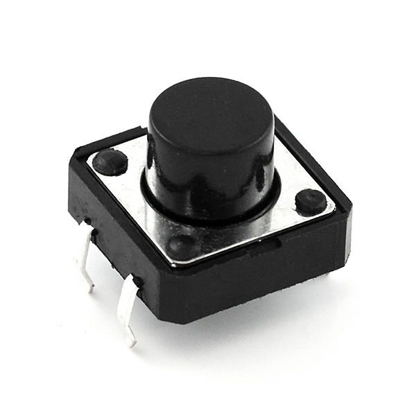
This is a standard 12mm square momentary button. What we really like is the large button head and good tactile feel (it 'clicks' really well). This button is great for user input on a PCB or a good, big reset button on a breadboard. Breadboard friendly!
Need a custom board? This component can be found in SparkFun's À La Carte board builder. You can have a custom design fabricated with this component - and your choice of hundreds of other sensors, actuators and wireless devices - delivered to you in just a few weeks.

Momentary Pushbutton Switch - 12mm Square Product Help and Resources
Interactive 3D Printed LED Diamond Prop
April 19, 2018
In this tutorial, we will learn about how to create an interactive theatrical prop for a performance by 3D printing a translucent diamond prop using a non-addressable RGB LED strip and AT42QT1011 capacitive touch sensing.
SparkFun Inventor's Kit Experiment Guide - v4.0
November 15, 2017
The SparkFun Inventor's Kit (SIK) Experiment Guide contains all of the information needed to build all five projects, encompassing 16 circuits, in the latest version of the kit, v4.0a.
Button and Switch Basics
May 7, 2013
A tutorial on electronics' most overlooked and underappreciated component: the switch! Here we explain the difference between momentary and maintained switches and what all those acronyms (NO, NC, SPDT, SPST, ...) stand for.
Wireless Joystick Hookup Guide
January 5, 2017
A hookup guide for the SparkFun Wireless Joystick Kit.
0 of 1 found this helpful:
Vertical Measurements
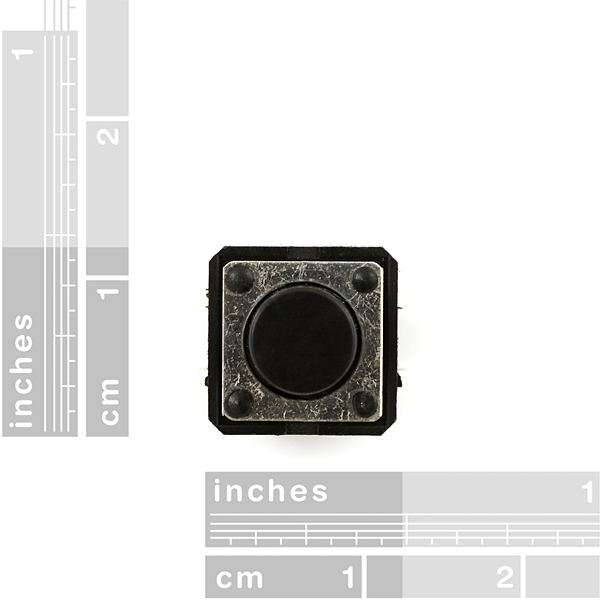
For those needing to know vertical dimension for these buttons. The height of the the body alone is 3.35mm; the height from the bottom of the body to the top of the button is 8mm.
NOTE: These dimensions do not include the legs.

Resources and Going Further
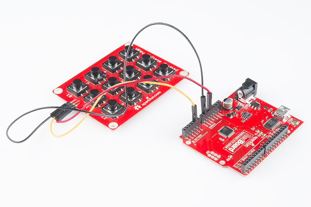
If you need to add a keypad to your microcontroller project, but don’t want to use up a lot of I/O pins to interface with it, try looking at the design files for the VKey Voltage Keypad. It outputs an analog voltage to encode which key has been pressed, which can in turn be read by an analog to digital converter on a microcontroller using votlage division.
Core Skill: Soldering
This skill defines how difficult the soldering is on a particular product. It might be a couple simple solder joints, or require special reflow tools.
Skill Level: Noob - Some basic soldering is required, but it is limited to a just a few pins, basic through-hole soldering, and couple (if any) polarized components. A basic soldering iron is all you should need.
See all skill levels
Core Skill: Electrical Prototyping
If it requires power, you need to know how much, what all the pins do, and how to hook it up. You may need to reference datasheets, schematics, and know the ins and outs of electronics.
Skill Level: Noob - You don't need to reference a datasheet, but you will need to know basic power requirements.
See all skill levels
Comments
Looking for answers to technical questions?
We welcome your comments and suggestions below. However, if you are looking for solutions to technical questions please see our Technical Assistance page.
Customer Reviews
3.3 out of 5
Based on 4 ratings:
2 of 2 found this helpful:
Provide a way to know how to hook this up?
Would be nice to know how to hook this up :)
Greetings. Here is a nice diagram I found in Google of the internal connections for this type of push button: http://elinux.org/images/4/4b/Mpushbuttonworking.jpg
1 of 1 found this helpful:
Not breadboard friendly
The legs are way too wide to easily fit in a breadboard. They are way too hard to insert (probably spreading the plates on your breadboard too much), and they pop out easily.
Please, SF, spec some buttons with truly breadboard friendly legs.
Sorry about this. You are right, these aren't the best for bread board applications. I will pass your feed back along to our parts hunters. Maybe we can get a good bread board compatible button. You can make these work, but they won't be super stable in the bb. Happy hacking
2 of 6 found this helpful:
Needs a Diagram
First, this switch is working out great for my project. It fit in my breadboard just fine, and works nicely with my Raspberry Pi GPIO pins.
I ordered 4 of these switches, and they came in a ziplock bag with no other documentation. Without experience, it's impossible to know which way the pins get connected when the button is pushed...there really needs to be a little circuit diagram included with the part. I had to use my multimeter in resistance mode to figure out how it worked...not a big deal, but I shouldn't have to!
Solid
I was expecting the smaller more flimsy push button switches that you get in some Arduino kits. These are bigger and more solid. The button also has more resistance, which in my case was not quite ideal because I wanted the weight of objects being placed on them to activate the switch. But I can imagine for most cases where you just want a nice tactile feel, this is a good thing.
I bought a SparkFun MIDI Shield with three of these switches, and assuming they're the same ones [I believe so] I can report that two of the three are failing after under 5000 presses. They're supposedly rated for one million presses,. But if I press down with a slight emphasis on on one side of either switch they'll click but not register an electrical contact. This is reliable and consistent. This is way worse than switch bounce: the switches won't even turn on. Additionally, the buttons have always been loose: if you press the switch, then wiggle it, it'll go on and off and on and off.
I have found these to be very poor quality switches.
I'm sorry if this is obvious to most of you out there, but if you've never worked with these (which I hadn't until I bought some of these buttons), this might be unclear: The legs of this button are NOT all independent connection points which are joined when the button is pressed. Rather, the legs form two pairs which are both joined when the button is pressed.
So how do you know which legs are linked? Well, look at how the four legs are curved. Legs that curve inwards towards each other are already connected even when the button isn't pressed. They connect to the other pair of legs when the button is pressed. Thus, in the main photo for these buttons, the two visible legs are not connected until the button is pressed.
Since these are standard to any Arduino inventor's kit, (not just the Sparkfun series!) that rule is largely correct. The smaller sized ones have a tag on the top thing, turning it to the left, will enable the switch. Incidentally where's the datasheet for these? I needed one once, and ended up visiting a shop's website, over in the SF area of CA. And the legs need to be flattened out to work in a breadboard, normally they are flexed for the ease of being inserted into most PCB examples, such the Protoshield.
If you want to save yourself the bother of worrying which side is which, simply connect your circuit to any diagonal pair. You'll never go wrong. Works for just about any 4-legged tactile switch out there.
This person is a genius!
For many switches, you can also check the underside for a horizontal line. The pair of legs on 1 side of the line are permanently connected to one another, while the pair on the other side are permanently connected to each another.
Or you can perform a test with a multimeter or a simple LED circuit. :) Or you can briefly short a low voltage battery, if you like a little danger on a chilly day.
I just spent an hour debugging, because I made this same assumption. Glad you posted this.
These do look like nice little switches, and I'm sure they are.
But when I try to plug one into my Breadboard Mini Adhesive Backed, the pins will not go into the sockets with the switch oriented the right way - one pair of pins on top and the other pair on the bottom, basically 90 degrees from how the switch is shown in the pictures.
The pins fit into the breadboard perfectly if I rotate the switch 90 degrees, but then the switch is shorted out by the vertical rails on the breadboard, right?
Can anybody comment on max power ratings?
How many amps and volts is it rated for?
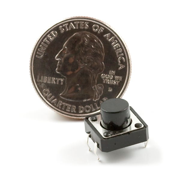
This really would be more impressive to show next to something like a coin or a USB arduino. Seems larger than the usual button
We can do that.
Is there a version of this switch that doesn't "click"? I want to make on of my devices quieter
These require more force to push than I like. If you need a switch that requires less force (perfect for a gamepad), use Omron B3F-5050 (1.3 N operating force). The B3F-5050's also have a "long service life" according to the datasheet.
I didn't read through all the comments, but a lot of people seem to need the datasheet for this switch. You can find it here:
http://www.adafruit.com/datasheets/B3F-1000-Omron.pdf
This switch is part number B3F-1000 as far as I can tell. The datasheet covers a number of different part numbers. Don't know why SparkFun can't provide a link to this datasheet under the part photo. Same comment for many of their parts. Datasheets are available for most parts if you know the mfgr's part number, but SparkFun doesn't usually provide that either.
Some of our more basic and older components don't have them. If you ever come across something that needs a datasheet please email techsupport@sparkfun.com and they should be able to find you one and get it posted.
Dimensions please? PCB footprint would be even better. Not using this in a breadboard.
Check out the comment right above yours :) ( In case the flow of comments changes: SparkFun Eagle library: TACTILE-PTH-12MM )
Can someone send me a link to the data sheet for this push button? I need to know the exact pin spacing for PCB design. (It is common for these buttons to have one pin spacing that is 0.1" but the other direction is slightly off - NOT square. And I need the EXACT pitch!)
I see that multiple people have requested this data and there is no response - such as adding a link to the data sheet on the product description.
If anyone has this information, please e-mail me at samuelaaronward@gmail.com.
Thanks!
Sorry about the lack of a datasheet, we post them if we have them. If it helps, the PCB footprint is in the SparkFun Eagle library: TACTILE-PTH-12MM.
Any datasheet or manufacturer part number? I'm looking for their life-cycle spec (how many clicks are guaranteed). Thanks.
Absolutely amazing. Only complaint is that they don't have it in different colors. Do you think you could do that?
if i plugged these into an arduino are they a digital or a analog? i want to know this because im a beginner
These can be connected to a digital or analog pins. Ideally, you would connect them from a digital IO pin to ground. Make sure you enable the pullups on the pin.
You can find a good example here.
I have to agree with J.D., these buttons are not the best quality. I've definitely experienced a lot of double hits, and it gets to be very frustrating after a while.
Hello, is there a datasheet for this button? I would like to know the operating force and travel.
That's soo... Cartman? "Are there gonna be any side dishes???"
Nice buttons, I could sit clicking these all day.
Infact I think I will :)
I find these horribly unreliable. Missed-hits and Double-hits abound.
I opened one up to see why it was so terrible and they're not much different from their tiny counterparts, but there looks like there's a lot of extra space between the contacts.
Good for a novelty, not much else.
That's completely normal; It's called "Switch Bounce".
This is not just bounce, I'm talking mechanical failure. 555s will not save you.
I don't think 555's are used to combat bounce very often. Usually it's just a capacitor.
Have to agree with Thnikkaman. You usually combat contact bouncing with a low pass filter or with waiting for a string of same states in your code. No matter which way you look at it you are looking at a slight delay if you want to debounce. We are using a mixture between these and the ones with the caps for our senior project and they are pretty reliable.
I find these buttons terrible for the basic breadboard on this site, they can't straddle the middle trough and will come out with the stickiness of your skin if you try and press it. The only way I could use it at all was to put it sort of crooked on one side of the breadboard and slip wires on the only exposed terminal for the row.
Is there a way in Eagle to define the component such that two pads are connected to the same "pin" in the schematic symbol? As it stands, the best I've been able to come up with is defining four pins in the symbol, and explicitly drawing connections to one or the other in the schematic.
I need pushbuttons for breadboard. This type of momentary pushbutton is supposed to be breadboard friendly. But I noticed that the legs are curve inwards towards each other. Will this pushbutton easily plug in the breadboard and easily unplug as well? Thanks.
If you straighten the legs and keep them in a 90 degree angle and place it in the middle of your breadboard it will fit good and will not pop out. At least on my breadboard!
Is this button normally open or normally closed?
Normally Open
Anyone know if this button is drop-in compatible with the buttons on the JYE oscilloscopes?
Is looks like the same footprint, only the actuator isn't as tall. Might cause issues if you're planning to put the little button hat on it.
Can someone give me the diameter and height of the round button itself? Thank you!
Height from top of PCB to top of button surface: 8mm
(Height = square button "shoulder": 3mm + round "button": 5mm)
These buttons are awesome, nice clicky tactile feel, and the height of the button extends far enough to easily be reachable through many enclosure materials.
Diameter 7mm
Can't quite measure the height sorry.
These buttons are AWESOME!