- Home
- NCP1400-3.3V Step-Up Breakout

NCP1400-3.3V Step-Up Breakout
Replacement:PRT-10967. The new version of this board uses the NCP1402, which is capable of sourcing more current. This page is for reference only.
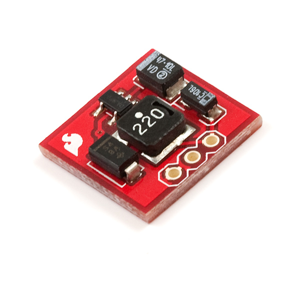
The NCP1400 is a 3.3V DC-DC converter. The breakout board will accept voltage inputs between 1 and 3 Volts (such as 1 or 2 AA batteries) and output a constant, low ripple 3.3V output capable of sourcing up to 100 mA. This board is great for supplying power to 3.3V sensors or providing 3.3V from a a single AA battery.
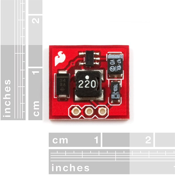
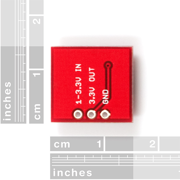
The breakout board includes the necessary peripheral components. The input, ouput and ground pins are broken out on a 0.1" grid to allow easy access on a breadboard.
Comments
Looking for answers to technical questions?
We welcome your comments and suggestions below. However, if you are looking for solutions to technical questions please see our Technical Assistance page.
Customer Reviews
No reviews yet.
Anyone use this with an Xbee? Having an issue when the Xbee transmits a signal, it draws 250ma or so. Very noticible on a scope....you can see the voltage just drop during the transmission. This messes up the idea behind the circuit......which is a temperature sensor. The LM36's require stable voltages to give me a stable reading. The circuit needs to be battery powered, so I love the idea of using this as opposed to a 3.3v voltage regulator. My circuit only needs to transmit every 15 minutes. I am thinking of adding some extra capacitors on the 3.3v output to try to compensate for the drop out.....Any advice?
Would this work to step a 3V coin cell battery up to 3.3V? Would it work in the battery was slightly over 3.3V? I've found a few 2032 coin cells are sometimes closer to 3.5V when brand new, wondering if this would cause an issue in this device.
Some more about the efficiency of this device, powering an ATmega328P at 8MHz (internal oscillator) at 3.3V from a single AA Eneloop battery reading 1.3V.
* Active: 3.8mA out 13.2mA in or 73% efficiency
* Active with small LED on: 8.0mA out 30.2mA in or 67% efficiency
* PowerDown Mode: 4.8uA out 470uA in or ~3% efficiency
Running it from 2 AAs (2.6V) improved the efficiency
* Active: 3.8mA/6.2mA (78%)
* Active with LED: 8.0mA/11.6mA (88%)
* PowerDown: 4.8uA/230uA (3%)
A fantastic device if you're going to be running all the time, but a little power hungry if you're designing something to run several months on a single battery.
I bougth and tested a couple to them. Great stuff.
Now I'd like to include this DC-DC converter feature in my own desing / PCB.
I'd a look on NCP1400 datasheet + NCP1400AV33EVB
Demonstration Board (http://www.onsemi.com/PowerSolutions/evalBoard.do?id=NCP1400AV33EVB)
Question about the Schottky Power Rectifier (D1)
From SparkFun Break Out board : MBRA140 (1A 40V)
From the On Semi BOM : MBR0520 (0.5A 20V)
Is the MBRA140 not a little bit oversized ?
I've space constraint with my enclosure. I'd like to get the same inductor reference as there is on the break out board.
What is this inductor reference ?
Why is it that the schematic for this board and the 5v version are exactly the same? Even the values of the components. What would it take to make a 12v or 24v version?
To answer my own question, it is because the NCP1400 is a NCP1400ASN33T1G on the 3.3V and NCP1400ASN50T1G on the 5V. Also, no 12 or 24, these chips only go up to 5V.
Hi
I am about to runs some tests with this little board. I am interested in the shutdown CE pin. I think with some handing work with a scalpel I can cut the track between the pins. But before I do I was drawing out different ways that I can get my device to turn its self on by a button press then turns its self off. using a FET(turned on by button) to pull the CE pin high is the best way I can think of. The micro pulls low on CE turning its self off. Has anyone got any clever solutions to turn the DC to DC convertor on and off?
Has anyone tried more than 3.3V input? I want something simple and lightweight that can regulate lipo batteries (4.2 - 2.7 V) to 3.3.
A LiPo battery shouldn't be allowed to fall below 3 Volts. And really it should be taken care of when it falls below 3.4V or so (speaking from experience, not science). If you want 3.3V from a LiPo you can just use an LDO instead of a booster. Something like this should work fine:
http://www.sparkfun.com/products/526
I tested a 3.3v regulator (probably the same as the one you linked, it came in one of the SF starter kits), but it seems to have a .9v (datasheet says 1.1) dropout, so I only get 3.3v if the lipo is fully charged.
I am considering this, though:
http://www.sparkfun.com/products/10255
Would be cool if that one had the same pinout as a LDO voltage regulator like this one does. Having the low voltage cutout onboard is nice, though.
I'm having some troubles with this module.
I'm using it to power a 2mw xbee module.
When using a single 1,5v cell, it's working great, but if instead I use a (fresh) 3.0v cr123 cell, the xbee module behave differently, and does not associate with the xbee coordinator (associate led stays fixed on)..
Very weird, as output voltage of the converter is 3.3v in both cases ...
Any ideas ???
Ok, I found where the problems came from ...
I'm using the "xbee explorer regulated" board, but I forgot to bypass the 5V->3.3V regulator, so the 3.3V from the step-up converter was not sufficient to power correctly the regulator, and the system was unstable ...
Now, it works great with any type cell from 1 to 3V.
Cool ;)
I thought it was a small miracle when I first got my 1:18 scale radio controlled R2-D2 up and running. But I was at my wit's end trying to get the dome lighting working. I had a 1.2 volt system and I needed at least 3 volts for the four bi-color LED's and the Picaxe 08m microcontroller.
Once again Sparkfun made the impossible possible. This little board's tiny surface mount components got me what I needed. As far as efficiency goes, I was surprised to find that it did not significantly affect the run time as I had feared it might... the video tells the story...
http://www.youtube.com/user/robmeyerproductions#p/a/u/0/xpYGeQhAkNA
Glad we could help. That's what we are here for.
It would be nice if the designer of this board had brought out the CE pin. The only way to get the most battery life using this thing is to shut it off most of the time.
What about efficiency? If this is providing 100mA @3.3v out, how much current is it sucking from a 1.2v AA battery?
Take a look at the datasheet. There is a plot of efficiency vs. current for varying input voltages. It looks like 100mA from 1.2V supply is something like 50% efficient. At lower currents its near 80% efficient.