- Home
- Product Categories
- Stepper Motor
- Stepper Motor with Cable

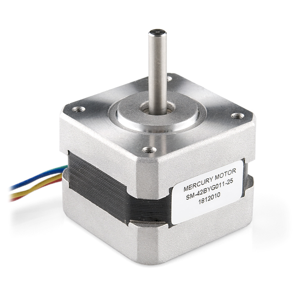
This is a simple, but very powerful stepper motor with a 4-wire cable attached.
This is a Bipolar Motor.
- Step Angle (degrees) :1.8
- 2 Phase
- Rated Voltage : 12V
- Rated Current : 0.33A
- Holding Torque : 2.3kg*cm
- 5mm Diameter Drive Shaft
- Winding resistance: 32.6 Ω
- Winding inductance: 48 mH
- Max flux linkage: 1.8 Vs
- Maximum Detent Torque: 0.016 N.M
- Total inertia (kg.m.m): 3.5 Kg.m.m
- Total friction (kg.m/s): 4 Kg.m/s
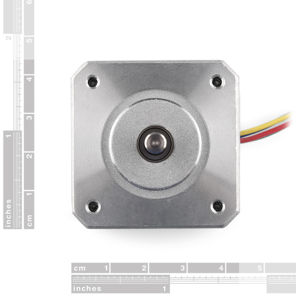
- NEMA 17 Mounting Hole Pattern (31mm)
- Motor Width: 42mm (1.67”)
Stepper Motor with Cable Product Help and Resources
Easy Driver Hook-up Guide
May 5, 2015
Get started using the SparkFun Easy Driver for those project that need a little motion.
Torque vs Speed Curves
You can find the "Torque vs Speed Curves" here .
Stepper Motor Mount
The Actobotics Stepper Motor Mount - NEMA 17 [ https://www.sparkfun.com/products/12987 ] is compatible with the Stepper Motor with Cable. I was able to use 4x "M3 x 6mm x 0.5mm mounting screws" included in the Actobotics stepper motor mount to attach it to the Stepper motor with Cable. The mounting hole pattern on the Stepper Motor with Cable uses the NEMA 17's hole pattern.
Maximum Speed w/ Example Code
Looks like the maximum stepper motor speed is about 240 RPM if you use it with an Arduino microcontroller and the EasyDriver. Check here for the example code that was used to test the stepper motor => https://github.com/bboyho/EasyDriver/blob/master/Firmware/Arduino/EasyDriver_StepperMotorWithCable/EasyDriver_StepperMotorWithCable.ino .
The number of steps for a full revolution looks to be about 1600 microsteps since the stepper motor with cable has a step angle of 1.8 degrees (...360/1.8 = 200 step stepper ) and the EasyDriver has a range of 8 microsteps for a full step.
Core Skill: Robotics
This skill concerns mechanical and robotics knowledge. You may need to know how mechanical parts interact, how motors work, or how to use motor drivers and controllers.
Skill Level: Experienced - Your experiences should include working with stepper motors and feedback system. You may need to understand how encoders and more complex control systems work.
See all skill levels
Core Skill: DIY
Whether it's for assembling a kit, hacking an enclosure, or creating your own parts; the DIY skill is all about knowing how to use tools and the techniques associated with them.
Skill Level: Noob - Basic assembly is required. You may need to provide your own basic tools like a screwdriver, hammer or scissors. Power tools or custom parts are not required. Instructions will be included and easy to follow. Sewing may be required, but only with included patterns.
See all skill levels
Core Skill: Electrical Prototyping
If it requires power, you need to know how much, what all the pins do, and how to hook it up. You may need to reference datasheets, schematics, and know the ins and outs of electronics.
Skill Level: Competent - You will be required to reference a datasheet or schematic to know how to use a component. Your knowledge of a datasheet will only require basic features like power requirements, pinouts, or communications type. Also, you may need a power supply that?s greater than 12V or more than 1A worth of current.
See all skill levels
Comments
Looking for answers to technical questions?
We welcome your comments and suggestions below. However, if you are looking for solutions to technical questions please see our Technical Assistance page.
Customer Reviews
4.3 out of 5
Based on 21 ratings:
1 of 1 found this helpful:
Nice!
Very nice product, works as described, would be even greater if it had a universal mounting hub included...
1 of 1 found this helpful:
Perfect for the job.
Used to drive a power focuser on a telescope. Plenty of torque and robust. Trial and error methods mean errors - no problem for this motor.
8 of 8 found this helpful:
Excellent
I own three of these motors, and use them for video production, microphotography (controlling the positioning of equipment), and robotics projects. They seem reliable, have enough torque for all of my needs (so far), and can be nicely driven either by H-bridge chips like the L293D, or by more feature-rich motor drivers like the EasyDriver.
But as I just discovered, working with SLF radio frequency, which is what you are generating when switching these motors (and all steppers) at typical speeds, is not always carefree. The RFI/EMI produced can interfere with sensitive input pins on microcontrollers, and in my case, an IR receiver module (Vishay TSOP38238). The solution is pretty easy, though - if a part is being influenced by EMI, shield it by surrounding it with grounded conductive material. You can buy shielding, or make your own. I am shielding my IR receiver module by placing it on a piece of PCB with a large ground plane that sits between the IR receiver and the stepper controller, output traces, wiring, and motor.
Another thing I like about this motor, which is perhaps a little odd, is the very long cable. I usually only need half the length. I cut it in half and braid it. But the other half I cut off? It makes excellent stranded hook-up wire! So hey, bonus hook-up wire :)
For hooking this motor up to projects in a reversible but still dependable manner, I recommend 4-pin mini XLR plugs and jacks. They can be pricey but are worth it because accidentally disconnecting a running motor while attached to a controller can destroy the controller. I have also used S-video (4-pin mini DIN) connectors in the past, but after trying mini XLR, I found it to be a far superior solution.
Last thing to note - you can dissemble these motors to see how they work, and put them back together easily. Once opened up, you just have to tug on the rotor a bit because there are fairly strong magnets in there. You can also reverse the axle so it comes out the other side - I had to do that for one project to get the motor mount where I wanted it.
5 of 6 found this helpful:
Stepper Motor
This makes a great low RPM generator for windmill , waterwheel science fair projects .. puts out 6 Volts AC at about 70 RPM which will power 5 V. LED's.
3 of 5 found this helpful:
Pretty good for power generation!
Bought this motor for a wind turbine (my university's senior project). Ran it with a 3D printed 3-bladed turbine, with a NACA 2410 airfoil, 5.25" span and 1" chord with a 0.45" hub (so the inner radius of the blade is 0.45" and the outer radius is 5.7").
Test setup used a 9.65k ohm resistor connected to two rectifier bridges (one for each output) with 0.32V forward loss schottky diodes and 1000uF electrolytic capacitors from DigiKey.
At 6 m/s freestream velocity, turbine spun at ~460 rpm and motor produced 31V. At 9.2 m/s, ~985rpm and 61V. At 11.9 m/s, ~1420 rpm and 70.6V.
P=V^2/R, so power at the three speeds was 0.010A, 0.385A, and 0.517A.
We also used the cheap circular stepper motor from sparkfun and it only produced 0.030A at 12 m/s and 1450 rpm.
EDIT: In an earlier review, I incorrectly assumed that the "friction" seen with this motor was due to the magnet rubbing against the outer walls. Actually, this "friction" was the detent torque - seen when the wires were shorted together. When used as a generator, the load (resistance) across the wires will determine the amount of detent when you try to spin the turbine.
A previous review wanted a universal mounting hub - we used SparkFun's 5mm to 1/4" shaft coupler to mount our blades, which could also be used with a 3mm to 1/4" shaft coupler for other motors.
Seems to work just fine
Didn't have much trouble at all getting this thing up and running with an Arduino Uno and a TI SN754410 H-Bridge.
Simple and Effective
It is a surprisingly strong and simple motor. I used the TB6612FNG with a 12 V wall wart and it started right up!
No Motor Mounts?
I'm the sure the motor works great but it's a NEMA 16 motor mount.....they don't sell NEMA 16 motor mounts and i'm having a very difficult time find one (anywhere).
I wish we had a motor mount too. When I need to mount these, I have used a plate that I drill to match the mounting holes. Not an off the shelf solution I know. But it might help someone. Thanks
Solid litte motor that does what I need
I'm making a diy eggbot/spherebot and I'm driving it with the Easy Driver. Not quite finished with the project yet but so far it's working very well.
Works great, might want to get some extras
This is a great stepper motor! It has plenty of torque but can also be driven to pretty high speeds before it starts to skip. I'm personally using it in a self-balancing robot, though I plan to buy another to try to build a little smart lock.
Connectors: These just come with long stranded wires—there are no connectors. I would highly recommend using a JST or XLR (like RobotCamera recommended) to connect these. You can even solder a 4-pin JST to your board (like an EasyDriver) to ensure that you always hook up the motor correctly, and that it doesn't come disconnected while the driving circuit is running (which can destroy your circuit). I think Sparkfun sells JSTs labelled as "polarized connectors" but you can easily find huge packs of JST connectors ready-to-crimp. Then, buy some cable braid so that your cables don't go spaghetti all over your build.
Side note: I kind of wish that they just had a JST jack on their side instead of the wires. That's how my 3D printer's steppers are connected, but this works fine too.
Mounting: These don't seem to be easily mountable from the back—only the front. I haven't tried, but I think removing the back screws would result in the motor housing coming apart, which isn't great for mounting. The fact that these are front mount only is just a little caveat to note. They're very sturdy regardless of how you mount them.
Working fine
As a hobbyist I am not stressing the motor but it seems to work fine. I have written code to ramp up/down to meet my needs.
Works as expected
These stepper motors work as well as i expected, i bought 2 of them and one seems to skip periodically, If you spin the shaft while it isnt even hooked up to power the bearings kind of bind every third or forth rotation, seems to only effect long runs.
Hello, and thanks for the review.
Make sure the wires are not touching each other because that can cause an issue like you're describing. If it's not the wires and the bearings seem to be the issue, contact us using this form for help.
Good motor, decent torque
Only complaint is that the wires that come off of this motor are a pain to strip.
Works great, love the long cable!
I'm using this with the actobotic mount, standoffs and shaft coupler, and everything works great.
I use the EasyDriver with a 12V, 1A power supply without issue.
The long cable is helpful.
Nice motor
I tried this motor along with the "EasyDriver - Stepper Motor Driver" board to get a feel for working with the stepper motors using the Raspberry Pi 4B. Originally I tried using the Pi-Plates Motor board to control a generic NEMA 17 stepper motor, but without getting them matched up (amp-wise) I ended up losing the Pi-Plates board to a learning experience... Getting both components recommended at SparkFun solved the issue, and IMO the EasyDriver offers more advanced control of the motor than the Pi-Plates board does.
Works great with EasyDriver and Raspberry Pi Pico
I bought this to be controlled by a Raspberry Pi Pico RP2040 and found using an EasyDriver and MicroPython, the stepper motor performs very smoothly. I'm looking forward to adding this to a Robotics project.
0 of 3 found this helpful:
problem with bearings
i buy four parts, while 2 of them have problem with spring force and this stall the rotor when try to rotate it by hand
i fix it no big deal
We made a neat printable case for the stepper motor and you can download it for free from Thingiverse
Check out the cool Mini-lift project we made with this stepper motor
Where can I find gears that fit the shaft of this product. I found it is about 1/5in
This says it is a NEMA 16 but there isn't stepper motor mount - NEMA for actobotics however the video references it. Does this work with another mount that I just can't find or is there not a mount available for this?
So in the description this is listed as NEMA 16 but it really seems to be NEMA 17. I hope thy reply to my above comment.
I've got this motor working very nicely with an L293D quad half-H-bridge, a 600mA 12v supply (I might use a higher current supply, as this takes it to its limit), and an Arduino UNO. I'm running it at 120rpm. It also runs fine at 240rpm, although torque is lower, and if you accelerate the motor to 240rpm, there is at least one resonant frequency at which it will skip steps.
Both full and half stepping work well.
It gets comfortably warm, but not hot, after about 40 minutes of continual use on full-step mode (which has both coils energized all of the time, so uses the max current).
Hi, How hot are these steppers suppose to get? I am running them for 20 minutes, they are very hot. I could not find the data sheet anywhere.
The same observation. I have some 3D-printed part around it, and they start to smell like heated plastic after a while...!
I'm also having this problem during test, running the motor at 12v, it's incredibly hot. It seems to be working, but I wonder, if is miswired, etc? Is there a way to verify that it's wired properly?
Hi. Is this a Bipolar or a Unipolar Stepper Motor? Can I control this motor using ULN2003 IC?
Bipolar.
just for people who buy this ive made a post on my blog for creating a surveilance system using the motor http://garagedeveloper.wordpress.com/2009/12/05/the-diy-surveillance-system-using-a-webcam-part-1/ . all is open source with code so :) thanks spark fun
Hi, I need some help. I have connected a stepper motor (ROB-09238) to easy drive (ROB-10267) and the current supplied to the easy goes up to 640 mA on 12V. The motor gets really hot (still works) but I would like to know if this is a normal operation. Signals at DIR and STEP are TTL. The motor coils are well connected. The pulses frequency can go from 100 Hz to 2 KHz and it is the same situation. I have replaced the motor and the easy and it is the same. Thank you.
I know this is a bit late but, Check the cables with an oscilloscope, the positive pulses you're probably sending are too short compared to the negative pulses.... I used to get that with my Nema 23 steppers and the AutoDriver...
AgustinGS thank you for your answer. I did check the cables and I saw the pulses on my scope. They look ok. I did a little bit more testing. I connected 2 LED back to back with 1K resistor each as one set of coils and another set of LEDs for the second set of coils. I was able to see how the signals change per set of coils when I send pulses from my Signal generator from low and high frequency (couple of HZ to 10Khz). I was able to see that always both set of coil are energized when pulses are not going in the easy drive. +5V / 36 Ohms aprox 140 mA. times two I was able to read aprox 280 mA total from my power supply. Now, 12V/36 aprox 334 mA times 2 aprox 670 mA. I think that is what is going on the easydrive chip can take that current but it needs an aluminum on top to dissipate heat. The motor can not take 670 mA. It gets very hot unless it is hooked to some kind of heat dissipation thing. I would say the 330 mA rated is per phase. I had to use the sleep mode to turn the voltage off from the motor. If somebody knows more details about this system combination: stepper motor (ROB-09238) to easy drive (ROB-10267) or have some comments on what I wrote please let me know.
On the easy driver I have to current turned down, but these motors still get too hot to touch after 30 min or so. Is this normal?
It had this problem for me when I had it mis-wired. I'm driving my Arduino at 12vdc, 500mA, and using the Vin on the Arduino to the M+, and it works fine.
I'm running one using the easy driver, I have the current pot, turned all the way CCW, at 9 Volts. It is slightly warm to the touch.
Hi
I have bought 2 motors. One of the motors is working fine in both directions, yet the other one rotates sluggishly in the reverse direction. When I, for example, set the speed to 1000 and the number of steps to 5000, in the positive direction, it rotates 5 seconds and displaces the attached belt 7 cm, but when I reverse the direction, it still rotates for 5 seconds, but at a low rate, and thus moves the belt only about 4 cm. I detached the belt as well and observed the motor separately, but same sluggishness persists. Any ideas? Has someone faced a similar issue?
Hi there i nead stepper motor (mercury motor SM-42BYG011-25 1.8*) code in c for Beaglebone black please help me.. thanks..
So in the description this is listed as NEMA 16 but it really seems to be NEMA 17. Am I wrong or is this product description?
Bought one of these with a Big Easy Driver for a clock project I built for school and it worked flawlessly. Makes a little bit of noise even if the current is pretty well dialed in, but otherwise functions perfectly.
Hi there
I created a circuit with a 5V stepper motor with a ULN2003AN like this one >> http://www.betasix.net/wp-content/uploads/2011/02/unipolar_stepper_bb.jpg
Can i use the same circuit i did for the specific step motor ?
thanks
Hi,I come from China.I want to know how can I get the products?
Hi, we ship internationally. Just add the items to your cart and check out. You might also want to check out distributor page as there might be a local distributor that has what you are looking for with much cheaper shipping rates.
“Rated Current : 0.33A” - Is this per coil or total current ? Should I set the pot on Easy Driver to 0.33A , or 0.15 (if it is per coil) ? Thanks
"Rated Current : 0.33A" - Is this per coil or total current ? Should I set the pot on Easy Driver to 0.33A , or 0.15 (if it is per coil) ? Thanks
Does anyone have better dimension specs on this? Specifically the hole positioning. The datasheet seems a bit out of order when looked at closely. Thanks!
I wish they would post the nema size on these motors. From what I've read a NEMA 17 motor will be 1.7 inches between hole centers. A NEMA 14, 1.4 inches, etc. From looking at the picture with the size scales i assume this is a NEMA 14.
Confirmation?
Thx
I think it is actually NEMA 17, I think the NEMA size refers to the body size, not the hole distance, but it is listed as NEMA 16 so im a bit confused. The whole dimensions match http://www.servocity.com/assets/images/555152_Schematic.jpg which comes from this page under NEMA 17 http://www.servocity.com/html/stepper_motor_mounts.html#.VE2TVfldUgl
Does anyone know what kind of arms are designed to be attached to this motor? I'd like to avoid gluing, taping, or stabbing things onto my motor.
For high precision stuff you really need a flat notch. Most of these motors don't come with a shaft that has a notch, but fortunately, they're not too hard to add. There are lots of tutorials online on how to do this, but basically tape off all holes with masking or gaffers tape, clamp the shaft into a vice or something (so it doesn't rotate while you file it), and then just take a metal file to it (slow and steady wins the race) -- when satisfied, remove the clamp/vice, shake off all the metal dust (taking care that none falls into the motor), remove the tape.
it has a 5mm shaft, so something like this would be good for attaching things.
I Bought this motor, could anyone help me with a MIKROC code for half stepping, left and wright?
I'm using PIC16F877A and L298N
Thank you
Hi, I am learning the L6470.But I do not know how to set the parameters like KVAL_RUN,KVAL_HOLD,KVAL_ACC,and so on. In oder to meet my own motor, I have used the dspin evaluation tool to calculate the parameters.but it didn't meet.How can I set them? Thanks!
Do any of the Actobotics motor mounts fit the hole config on this stepper?
Just as a warning: taking apart the stepper motor like in the product video will probably ruin it. I have heard that the permanent magnet does not like to be pulled out like that, and once you let the magnetic field out, it will not go back.
Hello. Do you know of a suitable adapter between this motor and this omnidirectional wheel? http://www.robotmesh.com/vex-robotics/wheels/2-75-omni-directional-wheel-double-roller-2-pack
(I am involved in a competition for an autonomous vehicle.)
I am a photographer looking to build a slider that can vertically lift my equipment.
With large timing belts and toothed gears, I'm looking to lift about 4-5 pounds.
Does anyone know if this little stepper motor is capable of lifting that kind of weight vertically? Or should I look into purchasing a higher-torque motor?
Thanks
You might want to consider using this stepper instead. We've had customers use our stepper motors for similar projects in the past, but I think they were using the motor I linked to.
I AM TRYING TO CONTROL CURTAINS AT HOME USING THE ARDUINO + MOTOR SHIELD I HAVE THIS STEPPER MOTOR RS 5350372, BUT I AM NOT SURE IF THIS IS ENOUGH TO DRIVE THE CURTAIN. WHAT ABOUT USING ONE OF YOUR 12V STEPPER MOTORS ?
No need to yell.
which motor shield? we don't sell a shield that drives stepper motors. you will need an easy driver or something that is made to specifically drive stepper motors.
http://www.youtube.com/watch?feature=player_embedded&v=4VHW5KdvClo
i think it would be nice if you could also have lead screws and guid rods A4 table lets say.
Or if there is anyone can give us a webpage that can easily find all the component we need for this specific motor.
here is a control circuit for the stepper motor and the big easy driver.
http://www.youtube.com/watch?v=UaaGpVkjQAc
I am considering using this motor to drive the focuser on a telescope but I cannot find its torque quoted anywhere. The details only quote a value for the holding torque. thanks for any info. Mike
dear all i have a simple question.
The motor is rated at 12V and 0.33A. If i like to connect a power adapter that can supply 12 Volts and 1A, then does the motor gets what it likes which means 0.33A?
I think the load will get what it needs (in this case 0.33A) and not what we can supply (in this example 1A).
The pot in the easy driver is there to control more powerful motors.
Could you explain to me what should i take are if i'm wrong?
thanks a lot.
Does anyone have a good source for timing pulleys with this diameter bore (5mm)? Thanks!
Inventables.com has them in 5mm and 1.4 bore. My wife got me a shapeoko so I got the standard 5mm and ordered the 1/4" bore a week later. I just mounted them yesterday. They also sell the matching timing belts.
Hi, Anbody know which type of stepper motor it is PM or VR or Hybrid?
Since the motor still magnetically holds position when turned off, I'm guessing PM.
Just a warning for people who buy this motor, it is highly dependent upon proper delay times between motor pulses, if you're using your own motor driver design. I documented my issues with it here, showing off how delay times of 5ms down to 1ms affect it http://www.youtube.com/watch?v=EGJFYAy7bic&feature=youtu.be
I was annoyed at difficulty of finding cheap 5mmx1/4" shaft couplers, so I made one: http://www.shapeways.com/model/774627/f006.html
Will report on efficacy of 3D SLS part in several weeks. --Karl
UPDATE: Coupler works fine, but I abandoned leadscrew design in favor of timing belts because they are cheap and fast.
HI, I use this motor (SM-42BYG011-25) with an Easy driver and Arduino. When I feed in 12 V (to easy driver) the motor is stuck (power source 12V, 2 A), when I use 5V to supply the arduino instead the motor works fine but the torque and speed are low. I checked the widening sequences with led at full step and work fine. Any body knows why it doesn't work at 12V.
It should not be stuck - I run your exact setup no problem at 12V, 24V, and even 30V. (Also, they do work at 5V as you found, but are very weak.) E-mail me at brian_schmalz@yahoo.com and I can help you figure out what's wrong.
*Brian
how much does this motor weigh?
According to the datasheet, it weights .20KG(or 0.44 lbs).
just a comment: so , yeah , i got one order of 2 of theses motors (quite some time ago), but strange thing , they re not identical !!!
both have the exact same sticker and look the same , but on one of the motor , the hole on the back is smaller than the other one , and also , this motor is noisier than the other one , like it is quite audible ,and it is running on my nerves, but they re running exactly the same way .
Hi! I have a 12V and 1.5 amp power supply for two of those steppers. Since they are rated 0.33 amp, I was thinking having a 3 way current divider circuit to route manage the power supply, routing .35 amp to each stepper motor and the remaining .8 amp to additional circuit to either use and/or transduce into heat. Is there a clever way to manage the difference in power supply and stepper amp rating? Assuming I cannot replace the power supply with a smaller one more adapted to the 2 steppers. And second question, how does the amp consumption will evolve with speed variation? 0.33A on 12V at what speed?
Thanks to Ohm's law, current (very helpfully) doesn't work that way. A power supply is rated by it's voltage output (which stays constant), and a maximum current capacity. Without anything connected to the supply, its voltage output will be e.g. 12V, but its current output will be 0A since there's nothing to draw any current.
Anything you connect to the supply that does draw current will basically use only what it needs. So you can connect your power supply to all your motors and other circuitry in parallel, and each one will only draw the power it requires at the speed/load you're running it at. As long as everything you have connected isn't drawing more than 1.5A total, your system will work fine. No extra current-dividing circuitry is necessary.
I'm not sure of the answer to your second question. For motors, current consumption generally goes up linearly with an increase in speed, but I don't know what speed the rated current corresponds to, or if it's just an indication of the resistance of the driving coil. Anyone out there know the answer?
Stepper motors draw a fairly constant current when the coils are energized, regardless of speed. This motor contains two-phases. Each phase is essentially a completely separate electromagnet with 34 ohms of resistance. At 12V, when both coils are energized simultaneously, the motor draws 706mA. When only one is energized, the motor draws 353mA.
Whether one or two phases are energized and how often is based on the drive mode. In two-phase on, full-step mode (probably the most common mode), both phases are always energized regardless of speed, and at 12V, this motor draws 353mA per phase - 706mA in total - constantly. Even when it's not moving and just in a "holding" state.
Half-step mode uses a bit less current, because half of the time, only one phase is one. So in half-step mode, you can expect this motor to draw 530mA at 12V on average. The current it will draw in a holding state depends on at what stage of the drive mode the motor was held. If you are programming your own logic, you can actually control this - which might help prevent overheating.
Now, it's possible that some motor drivers will switch off all phases in between steps, regardless of drive mode. I have no idea why they'd do that, and mine certainly doesn't (it's just an L293D that I control will a shift register), but I'm just covering my butt here. If your driver does this, then it's possible for speed to have an effect.
For stepper motors, the speed doesn't determine the current use, but rather, the drive mode does. The drive mode and speed together determine the torque. In general, more torque is correlated with more current.
Thanks Mike for clarifying this for me. I tested the current consumption and here is what I found, there is between 0.2A and 0.35A of current consumed when in motion but the consumption interestingly jumps to 0.520A when at still. I did a quick test to validate my theory and it seems that if I constrain the Amps directed to the motor then the holding torque lowers and it becomes easier to rotate the shaft by hand despite the applied current. Doesn't that mean this Stepper should be rated 0.52A rather than 0.33A if it draws 0.52A to maintain a still position at full torque or does it mean that Amps should be electronically constrained to 0.33A to limit heat and avoid shorten life? I got to say as part of my discovery of that I am pretty pleased by the strength and accuracy of this little motor. The only down side is that there are no details on wiring polarity and actual wires on the motor which forced me to try quite a few configurations before it worked with the IC driver. A better doc/datasheet could have saved me a couple hours during my last weekend.
The above question was about shaft couplers, but I am interested in a motor mount. Since this looks like a NEMA 17 size, I looked for motor mounts of that size but, surprisingly, was not able to find any (including looking on McMaster-Carr).
Any suggestions for a motor mount for this motor? I also have a NEMA 14 size stepper that I need to mount, so suggestions for that size would be appreciated as well.
Does anyone know (or even tried) a worm drive suitable for this stepper motor? Besides the "Universal Mounting Hub" compatible with this motor, I could not find any other mechanical parts available on sparkfun.com :( In my opinion, things like shaft couplings, worm drives, etc. would be very useful for any robotics project. I know that Sparkfun is more electronics oriented, but it would be nice to find all these things in one place.. Thanks in advance!
We're still a relatively small company, with limited inventory space, so we have to be selective about what we do and don't carry. Most of what we offer is the stuff we're good at (red boards), and we try to have enough extra hardware to get most of your project done. But for more esoteric hardware, we're happy to point you towards cool companies like McMaster-Carr which have vastly more mechanical stuff than we'll ever be able to carry.
Thanks a lot for the info! They seem to have a bunch of mechanical stuff there! :)
I'm confused by the holding torque on this stepper. The data sheet says .23N.M, but the description says 2.3kgcm. Just using google to convert 2.3kgcm is ~207 oz.in, but .23N.M is only ~32 oz.in Unless I'm mistaken about how to do the conversions. I'm guessing it's the latter (~32 oz.in) though because at only .33A per phase I doubt it's capable of much more than that.
according to http://www.numberfactory.com/nf_torque.html 2.3kgcm is ~32oz-in
do you think this can work in a hobby-cnc?
would this be enough to close/open some roller blinds? thanks
Hi,
I'm using a bunch of these Sparkfun steppers with Easydriver, and everything works fine, except the steppers seem to have very little torque; for instance, I can easily make them stop turning by simply applying a little pressure with two fingers; I don't need it to run a mill or anything remotely that demanding, just raise a 40g weight by turning a screw... Is there any way I can (first) measure the actual torque the stepper is building, and (then) improve it?
Thanks, G
You must have much stronger fingers than I! With the EasyDriver current limit pot set to full 750mA/phase (which way to turn it depends - don't depend on the silk screen being right - measure the voltage at TP1 and adjust pot for greatest TP1 voltage) even at 9V input I can not stop the motor from turning at speeds less than 1000 steps/second.
How would you apply a plug like this http://www.sparkfun.com/products/10551 ?
What kind of plug would you put on the end of the wires and how would you put it on?
Is this stepper motor rated at .33A per phase for a total of .66A?
I am going to build a reprap soon, and I was wondering if these steppers would be adequate for the 2 Pursa z motors. and possibly if sparkfun's new 400 step/rev steppers would be good for everything else
Thanks
When will sparkfun publish an arduino library for the EasyDriver ?
You might want to check this tutorial (in case you haven't done so already): http://bildr.org/2011/06/easydriver. It quite easy to follow and implement. Hope this helps!
That bildr tutorial is absolutely excellent. I've also put up a page that may be of use to you - Arduino examples, with the fabulous AccelStepper library: http://www.schmalzhaus.com/EasyDriver/Examples/EasyDriverExamples.html
*Brian
No need - there are several libraries out there for stepper motors. The one I use a lot, and really like (and supports Easy Driver and Big Easy Driver out of the box) is AccelStepper (http://www.open.com.au/mikem/arduino/AccelStepper/). It now even works with PIC32 based chipKIT boards and the UBW32. See my video for an example: http://www.youtube.com/watch?v=7Ga6RMYwuQI
*Brian
Any guidance on what the screw definition in the Spec sheet means? 4-m3, and 4 .5mm. It was asked earlier with no reply. This seems like something people would like to know.
I am using Qty(4) of M3x.5
I think the number 4 in the reference is the Quantity needed.
I agree thats a really goofy way to show the screw call out.
Thats a metric 3mm screw with a 0.5mm thread pitch and 4 needed.
Basically a standard off the shelf metric screw.
Oh yeah, The screw holes in the motor are about 1/2 in deep.
Hope that helps.
Thank You, Jagrolet.
I picked up these screws at my local ACE hardware, Home Depot didn't carry anything under 4mm.
Can you drive this with less than 12V? I would like to use a 7.4V lipo battery for short time frames.
yes, they can work on lower voltages. a 7.4v lipo should be good for them. keep in mind if you have the motor hold, it will drain the battery quickly.
I bought 4 of these in May for my Mendel 3D printer. One has failed - on the Y-axis. What is the warranty, if any?
This Stepper Motor really woks great with the Domo*pes lots of torque at high speeds.
http://cncsnap.com/node/149
http://cncsnap.com/wiki/domopes
Thanks for caring a great Product sparkfun.
Anyone know where you can buy gears/chain/mechanics to use with this motor?
In my (limited) experience with steppers 2 things would always cause them to vibrate but not spin. Either trying to drive them too fast (speed must be ramped up gradually) and hooking up the wires incorrectly. A google search will turn up loads of help, and a multimeter is a must for figuring these things out.
Does anyone have the solution for the question that a lot of people asked...My stepper motor just vibrates, and won't spin at all. I'm using the adafruit motorshield as a driver. I've already tried flipping phases, changing voltages, etc. I'm only trying to get the thing to spin at 10rpm. I never knew using a motor could be so complicated!
Will i be able to power this with this supply: http://www.sparkfun.com/products/9442 ??
I'm trying to wire this motor up to the Adafruit motor shield but i can't seem to get the wiring right. Can anyone help? What colours go where? Everything on the board has been tested and is working fine.
I just wired it up - it wasn't too hard, but took a bit of swapping to get the rotation going (if they're swapped around, then the motor will just vibrate or step back and forth).
For the record, my wires are like this:
Motor connections 3 and 4 are the same, just rotated 180 degrees on the board(swap M3 for M1 above, and M4 for M2).
This assumes that the colours don't change, but given that they're on the data sheet, it's probably reasonably safe ;)
hello everyone. where you can find a gear reduction with ratio of 10 or more, for this motor?
I am using this with the easydriver and everything worked perfectly. However, I took off the bottom of the motor in order to mark where I would place it (i thought I could use the screw holes on the bottom to mount it). But now, when I connected everything back together, I power up the board and the stepper motor just holds steady, it does not turn at all. I didn't know if this sounded like a problem w/ the motor or the electronics.
Disassembling a stepper motor like this will normally render it unusable.
I wish you add belts and pulleys for this motor as it is essentially parts of most automation and control projects .
4-M3 4.5mm for the screw holes.
How do you read that? Is that M3 x 4.5mm?
I'm using this motor with the Easydriver. The Easydriver will limit the current up to 0.8A. This motor needs 12V - 0.3A. I only got a power supply 12V - 1A.
Now I'm wondering, will it be safe to feed the motor 0.8A with the Easydriver? Does this mean I have to let it rotate slower because else the motor will burn? I'm new to this (trying to build a CNC) :) THNX
I overlooked the 150mA - 750mA function on the Easydriver. Just going to give it a try.
And no, it's not going to be a big CNC, just a toy hobby one..
Well it can do it as long as the slides have nice low friction, tho Z might be an issue
The motor is the same mounting and shaft size as the smaller (or older) zenbot machines, though you probably wouldn't be able to use it on one and actually mill anything.
That being said, it is a stepper and you can learn the same mechanics of a very large system by experimenting with these tiny motors for a very low cost. I adore these motors myself ... if you finish that CNC, post some links about it :)
EDIT: I just tested the motor on my smallest table and it did better than I expected. You will probably be able even to do light engraving with the right setup and most of all you will have fun trying, good luck :D
2.3kg*cm doesn't sound too bad. And ofcourse there are a lot of tricks to 'help' the motor a little bit. Fine threads will require more rotations but less torque.
Anyway, thanks for the info! Hope my motor doesn't get too hot ;)
It will get hot and wear out much faster. It will probably be too hot to touch after an hour of machining ... this motor doesnt have the torque for a CNC unless you are milling only styrofoam hahaha
The worst part is you wont get much additional torque at all from that extra 500mA ... just lots of heat :)
For this motor ... think plotter, not milling machine
Will this item come back in stock soon?
Can anyone tell me how many steps this motor can cycle through in one second? Is there a min / max to what you can set with the Easy Stepper?
It says 0.33A. Is that the max amps the motor should ever see from driver? Or the amount it draws?
I have had it up around 210rpm. But hard to go any faster because of the ~1ms signal delay you need between high/low signals sent to the board. It seems to me a better general step driver would be a board that you raise one pin high to move and the driver handles the timing on the board. Another pin would output step completion signals. That way you have a feedback loop and can take Step pin low after N steps complete.
0.33A is the amount of current that is completely safe to continuously run through the windings. The motor will draw its rated current at its rated voltage ... generally you will make an adjustment for the voltage(and consequently current) on the driver, read the datasheet of your driver
If you want to receive a pulse as feedback instead of pulsing the driver yourself for each step, its up to you to do some work (obviously) :D
I used these motors in a drawing machine installation we called SADbot: the Seasonally Affected Drawing robot. Check out the Instructable here: http://www.instructables.com/id/SADbot-the-Seasonally-Affected-Drawing-robot/
Did anyone else have problems with these burning out after a while? We had the installation on daily for about 6 hours, and over the course of about a month and a half had to replace 2 or 3 of them. A few students of mine used them as well and they burnt out after much less usage.
4 wires, no directions. What wires go where using the mini stepper sold here? tia
Hey Sparkfun,
Could you please answer these questions?
1. Will this motor work with EasyDriver Stepper Motor Driver (sku: ROB-09402)?
2. Please tell me Wall Adapter for this motor.
Thank you very much.
D
I bought 3 of these and got 3 matching easy drivers v4.3 <br />
I measured the wires and got 34.5 ohms on the following pairs of wires:(red, green) (blue, yellow) ...any other combination yields 0 ohms.<br />
<br />
I connected one pair to [A] and the other to [B] on easy driver. (Gnd, Stepper, Dir) on the easy driver gnd and stepper are connected to digital pins on an Arduino Uno (gnd is not connected to anything).<br />
The power source a power supply that reads 9VDC @ 800ma (even though when i measure the voltage it reads 13.2 Volts). <br />
<br />
When I power everything up and send it pulses to step it does step and it changes direction. The problem is that it jitters way too much and is very noisy and it doesnt stay in one position. <br />
<br />
I connected MS1 and MS2 to the Ground and Positive pins of the power connector using a 10K ohms resistor in an attempt to disable or enable Micro Stepping, and that had no effect. Playing with the current regulating Potentiometer on the easy driver didnt help either.<br />
<br />
What am I doing wrong? <br />
<br />
Thanks for your help!
Try connecting it to ground, usually it helps when you have a complete circuit.
I meant... "Dir and Step" are connected to pins on the Arduino. Sorry for the typo!
It says in the datasheet that the motor has a holding torque of .23 N.M. But not sure what the NM means. I have this stepper motor, but it does not seem to be able to turn heavier objects like a 1 pound 3 fit cardboard disc. I assume I need a stepper with more holding torque. Would I be correct?
What is the sequence for this motor?
I'm not sure what you mean. Maybe you can email techsupport@sparkfun.com and they can help you out. Sorry!
Another interesting DJ-related post:
This motor's torque drops it somewhere between a Technics 1200Mk2 Turntable and a Numark TT500.
...Also, stepper-motor vibration could be mechanically mitigated...
...Also 33.3rpm wouldn't be a problem for this motor...
Do you see where I'm going with this?
Someone please build a really smart turntable before I do. Do I have to do everything myself?
(Also... build the chassis out of laser-cut parts from Ponoko... and add fun lights... and maybe a little display of some kind)
I love these little motors. They are easy and fast to setup with the Easy Driver board also offered here on Sparkfun, and will work wonders in any project.
For those looking for simplified code for Arduino + Easy Driver + 2 button forward/reverse control visit:
http://currentamps.com/projects/2-button-stepper-motor-control
Warning. Just got 4 of these motors in the mail. 3 were fine, but the 4th wouldn't spin at all, even when cranked by hand. There was some mechanical obstruction. I opened up the motor and discovered that the insides were rusty with chipped paint on the magnetric drum.
Please check your storage conditions, Sparkfun guys. Also, before sending the things out, do a hand crank test. If the gears are welded, it should be obvious that that the device has issues.
Check the following shipment for rust, label: "Mercury Motor SM-42BYG011-25 23/2010".
Yep, we just realized this! We are removing the bad ones from stock right now. Email us at techsupport@sparkfun.com and we can take care of you. For everyone else, we will be removing any bad stock we have and hand-checking them all, so you can still order them, we will make sure that you don't get a bad one, thanks!
Shaft Copuling, look here
http://www.servocity.com/html/rigid_shaft_couplers.html
Greetings
FAA
I would like to find a way to couple this motor to a square shaft, but the link above doesn't work anymore. Thanks.
Hi!!! Does anybody know where I con buy a pulley/gear for this motor? thx!
McMaster-Carr is our go-to source for all things mechanical. Search on the drive shaft diameter and you should find all sorts of options.
Has anyone actually found the appropriate couplers on mcmaster? I can't find anything that's metric and smaller than 10mm...
Thanks, AKA
I am going to live dangerously and use a 3/16 (0.1875 in / 4.7625mm) double wide collar from Ruland (WCL-3-A). I saw grainger USA has 5mm inside diameter collars, but minimum order to Canadian subsidiary is 250 units X_x
How did that end up working on 5mm shaft?
This is for comparison to other motors (to show you how good this really is). Datasheet Torque converted. This little baby is two times more powerful for its current than any Ive found.
0.230000 Newton Meters
23.0000 Newton Centimeters
2.30000e6 Dyne Centimeters
2.34535 Kilogram Centimeters
2345.35 Gram Centimeters
32.5708 Ounce Inches
2.03567 Pound Inches
0.169639 Pound Feet
Which in turn make it's torque-curve drop of faster making it slower.
What sort of speed should I be able to get out of this motor?
I can't seem to get more than about 60RPM out of it, seems a little slow?
I've never seen these motors go faster than 60 RPM, fresh out of the box or old. If someone knows otherwise please speak up. Here is some handy info on stepper basics...in case you don't already know all the stuff in it:
http://www.solarbotics.net/library/pdflib/pdf/motorbas.pdf
I have one of these running at 300 RPM using an EasyDriver at 20V - it's certainly not a speed demon, but it's quite usable. The two tricks to getting it to go a little faster were disabling microstepping and using a higher voltage. Microstepping is useful if you need a very small, precise movement, but it only slows you down if you're trying to do fast, large movements. I had no trouble running at 180 RPM at 12V once microstepping was disabled. The second trick is to use higher voltages; the maximum voltage given for a stepper is usually the safe voltage to use without a current limiter, but you can generally use higher voltages if you have a driver that will limit the maximum current (like the A3967 on the EasyDriver).
I found that by using a smooth accelleration curve I can run mine at 600 rpm with 26v supply.
It's clear though that SparkFun should be selling a 2 or 2.5 amp version...
No, it's not the amps, it's the inductance that is killing the speed. The larger nema 17 is a low inductance motor and thus looses torque at speed at a much lower rate. You cannot beat physics, an inductor takes time to reach current, the larger the inductor, the longer the time. So if you cannot change current in the poles fast, obviously you cannot make a rotor spin fast with much torque. These motors were wound for 12 volts such that a simple H-bridge could drive them with no current limiting as the motors are "self" limiting by design. Modern drivers current limit the coil and thus you use a higher voltage, but this is really only effective on low inductance coils, otherwise it just ends up as waste heat (the high resistance factor comes into play).
Yes, higher voltage to the motor should charge the coil faster and thus run the driver cooler (faster charging means the gate sourcing the coils is open for less time). V regulator will be hotter tho working harder to make the higher input into 5V
I'm using an freshly ordered EasyStepper, tried half, quarter and eigth step modes, can't seem to get anything useful out of it.
I'm driving it with an Arduino running the RepRap GCode firmware, and I've tried it using a 2khz output from a DSO Nano scope, above 2khz it turns into a stutter.
Can you please identify the A & B wires for this stepper motor, and how they would connect to the easydriver ??
Thanks
John
Check out this site:
http://www.piclist.com/techref/io/stepper/wires.htm
Color coding isn't universal. Just get a meter and you can figure it out in a minute or so.
I assume this is a standard NEMA-17 mount stepper. If not, let me know. Also, I've been looking around the web for a wheel to fit this 5mm shaft. Does anybody have any suggestions? Ultimately, I'd love to put an omniwheel on this thing but for now a regular wheel will do.
Thanks,
Reggie
Try this: http://www.pololu.com/catalog/product/1203 also look around a little bit too, they have some good stuff that's allot cheaper then sparkfun.
I've found that rubber hosing from the automotive store works great for connecting two shafts of different sizes together, first a thinner width for the thinner shaft so the shafts are about the same size and then another section of hose (maybe 3" length) to connect the two, with metal clamps on either side.
Mis: If you go by measurements on the picture here, motor body face size is about 26 mm square, yet datasheet with link above specifies 43 mm. Which motor exactly are you selling?
i'd like info on this too. i hope to dear god its 43mmx43mm, otherwise i'm returning.
The datasheet is correct. We are in the process of posting a new picture showing correct scale. But the datasheet's dimensions are accurate.
oh good. that's fairly thick shaft at 5mm. wonder if i can machine a notch into it. it would be nice if it already had one.
For something this size, a set screw coupler would be fine, since it won't have that much torque to begin with. Good luck machining it. I've tried something similar on my milling machine and ended up polishing the metal and dulling a bit. It was fun though I guess.
You can pretty easily grind these shafts with a dremel cutoff wheel, or bench top grinder. Cutting them with steel tools will not work.
hahaha yes the hardened shafts are a no-go ... but quite correct, with this little torque it wont matter you have no flattened edge on the shaft for the grub screw
When do you expect these motors to be in stock again.
Do you sell any wheels that fit this motor? I see you have wheels that fit to the DC motors. It looks like the shaft diameter is 5mm. Thanks for any help.
Does anyone know where I can find a pull-out curve for this motor? I need to know the torque vs. speed characteristics.
Does anyone know how to use this with Ladyada's motorshield?
I have used it with Ladyada's motorshield, just follow the examples she uses on the website.
I just wired it up - it wasn't too hard, but took a bit of swapping to get the rotation going (if they're swapped around, then the motor will just vibrate or step back and forth).
For the record, my wires are like this:
Motor connections 3 and 4 are the same, just rotated 180 degrees on the board(swap M3 for M1 above, and M4 for M2).
This assumes that the colours don't change, but given that they're on the data sheet, it's probably reasonably safe ;)
I have this motor and the EasyDriver V4.2. I have looked at many different posts and it would appear that I have everything hooked up correctly. When I send pulses to the motor to drive it, the motor just vibrates. It may be a similar issue to that posted by Lyouss on Oct. 8th 2009. Another symptom is that when I do single steps, there are times when my power supply is drawing the entire amount of current (aprox. 0.6 amps) and there are times when the current drops to about 0.3 amps and the motor loses it's holding torque. Any help would be much appreciated.
I had a similar issue. Turns out I was trying to run the motor faster than it could. Try slowing down.
Also be mindful that you're not running it too slow. The FAQ on the EasyDriver site recommends running it at 500Hz (a pulse ever7 .002 seconds).
I think you're mis-reading my EasyDriver FAQ. There is NO lower speed limit for any stepper motor. You could take on microstep per year if you wanted to. I only suggest 500Hz as a nice speed where you can easily 'feel' any roughness in the motion, mainly for adjusting the current limit pot.
Hey, thanks for the FAQ, it was helpful when I was doing my Sr. design project. :)
It has been a while since I've tried to run the motor, but for some reason I could not drive it at low frequencies, it would just vibrate and sound terrible, not even take a slight step. Driving it at 500Hz made it move wonderfully.
Not sure where the issue was, but that's what happened. Now that I have an income I might just break it out again and try to build a robot or something.
You likely had your phases connected incorrectly
John, contact me at brian_schmalz (at) yahoo (dot) com and I can help you try and figure out what's going on with your setup.
If you go by measurements on the picture here, motor body face size is about 26 mm square, yet datasheet with link above specifies 43 mm. Which motor exactly are you selling?
Seems to be a nema 17 (31mm)
Great motor. Any source for similar motors but smaller?
Thanks
Found in the datasheet: 1.8 degrees +/- 5%
This is a 200 step motor? What is the % margin of error per step? For example, with 5% MoE I can expect 1/8 step accuracy. With 10% MoE I can only use 1/4 steps reliably.
it looks like from yourtube videos I've seen that this motor used to come with a much longer shaft. Any word on whether this has changed with this batch of motors, or could the data sheet be off.
Is this NEMA 23? (Compatible with this tutorial:
http://reprap.org/bin/view/Main/McWire_Cartesian_Bot_1_2 )
No, NEMA 23 would mean the face was 2.3" inches in width and 2.3" inches in height (NEMA doesn't specify a depth.) This motor is closer to 1.7"x1.7" so I would call it a NEMA 17.
Batteries won't last long with a motor like this. You better use a power supply.
I tried to make it work with a little higher current, and I could feel the magnets move inside. Unfortunately, the head doesn't spin...
Any clues about what's happening here?
What stepper driver chip/circuit are you using? This motor works quite nice with the EasyDriver (also sold by SparkFun). But you can't just put current into this motor - since it's a stepper motor, you need a stepper driver circuit that will sequence the two phases correctly.
Or could it be that this stepper is bi-polar and my controller unipolar?
Yup! That could be it too. :-)
Thank you for the answer.
Of course I'm not just putting current into the motor.
I use a Unipolar Stepper controller from Phidgets (http://www.phidgets.com/products.php?category=13&product_id=1062) because I use it with max/msp and they objects for all their devices...
Again, I hear the magnets activate, but the head doesn't spin! I must be doing something right since I feel/hear the motor working. But something is wrong!
Also, I can't find a power supply with the right current/voltage combination!
Any help would be appreciated... thanks!
This is a bi-polar stepper motor (all 4-wire stepper motors are bi-polar) and so you will not be able to use a uni-polar driver with it.
The product description should be updated with this information.
What kind of battery do I need for this?