- Home
- Product Categories
- Development Tools
- EL Escudo

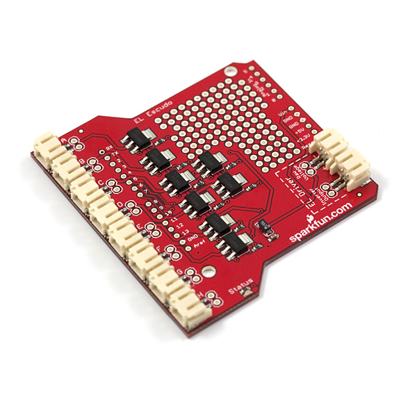
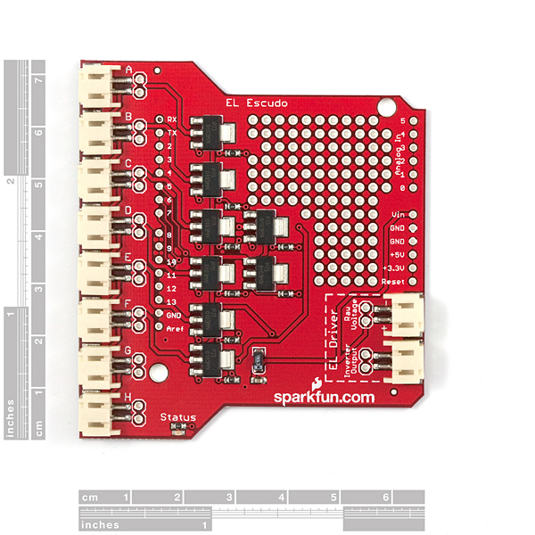
EL Escudo
Replacement:COM-10878. We've pushed this shield through a big upgrade! It now features zero-crossing optoisolated triacs and a 0.5A adjustable linear regulator. This page is for reference only.
The EL Escudo is an Arduino shield that drives EL wire. Electroluminescent wire is this really neat, flexible cord that emits a florescent light. Some times referred to as 'cool neon' because the cord does not heat up. The kicker is that EL wire runs on high voltage AC - about 125V at 425Hz. While EL wire requires very little power, you can't use normal transistors to turn on/off a string of it. So we created the EL Escudo that uses TRIACs to control up to 8 channels.
We also recommend using the Arduino Stackable Headers to provide enough clearance for the USB and Barrel Jack Connectors.
What do I use this for? Checkout the demo video. You can have a lot of fun with EL! The demo video shows 8 strands of about 12" lengths of EL. The length of wire is arbitrary - you can have 100ft wires, it doesn't matter! Your inverter must be matched with the length of EL wire but it's not exact. I'm pretty sure we've got a 5-15ft rated inverter driving 12" segments. The inverter may not like it, but it works. Check below for our inverters.
No really, what do I use this for? Oh! Oh, an example. Ok, checkout our tutorial on the Heartbeat Straight Jacket. It's a combination of EL wire and some fancy 2.4GHz wireless control. All built into a straight jacket for Burning Man.
EL Escudo Product Help and Resources
Sound Reactive EL Wire Costume
December 31, 2015
Learn how to make your EL wire costumes sound reactive in this project tutorial.
Comments
Looking for answers to technical questions?
We welcome your comments and suggestions below. However, if you are looking for solutions to technical questions please see our Technical Assistance page.
Customer Reviews
No reviews yet.
Four Points if you want to use El Escudo with an Arduino. If you take 30 seconds to read this post, you'll save yourself a week or two of headaches (I hope).
1) You need to buy header pins when you buy El Escudo. Three sets of these will do the trick: http://www.sparkfun.com/products/10527
2) When you solder in the header pins, don't include a pin for the Vin via on the El Escudo. Instead, wire a jumper wire from the Vin via to the +3.3v via/header on El Escudo (so you only get 3.3v on the El Escudo board). The El Escudo board routes Vin to the Raw Voltage for the inverter. USB power is 5v and that gets routed to Vin on arduino boards. If you don't make this mod, and you connect your arduino to USB, you'll fry your inverters. I learned this the hard way.
3) When you connect your inverters to the El Escudo board, connector with one red wire and one black wire plugs into the "Raw Voltage" port. The connector with two black wires plugs into the Inverter Output port.
4) The El Escudo example library on GitHub won't work with Arduino 1.0, and it has an error in the code to turn on the EL panels. I made a couple of mods to the code to fix these issues. You can find the updated code here: https://github.com/pkrakow/EL-Escudo
Hi! I have 12V inverter, Arduino UNO and EL Escudo Shield with an El Wire (everything is from sparkfun). I try everithing to make it work, but have no results. Arduino is powered from USB port and Inverter from 12V 3А wall power supply. After some trys I made a GND-HVGND connection, but still nothing. When I connect EL Wire directly to inverter it works good. But I cant open this TRIAC. Please help. Is it possible that my EL Escudo is damaged because I use it without GND-HVGND connection? Is it possible to control it from 5V powered Arduino UNO or it is needed to use 3.3V PRO version? I am very angry to Sparkfun for it, I spand a lot of money for this El goods with no result. ((
ISSUE SOLVED********* Inverter Issue is related to the Ground wire, Ground on the board needs to be tied to the ground of the inverter source(gnd of 12vdc) or the TRIACS will not work correctly. Hope this helps, I found this out accidentally when I was probing with my voltmeter the lights would come on. Its a little frustrating I burned out 2 EL wires due to arcing in the traces I induced by tapping the grounds together while troubleshotting.
If you tied the HVGND (16vac) you might have killed something.
For anyone who is banging their heads against the wall trying to get one of the SparkFun inverters (like COM-10201) to work with this shield, check to make sure that the output wires aren't swapped. (On mine, the input connector had red + black wires, while the output had two black wires.)
The connector on the output of my inverter was reversed, so the inverter would work just fine when connecting directly to a strand of EL wire, but the output would appear to be 0V when connected to the shield because both terminals were connected to GND.
I used a multimeter to check the resistance between the input and output wires. The GND on the input is connected to one of the black output wires, so (without anything connected to the inverter) check the three black wires to see which two are connected. The GND terminal should be on the right-hand side (looking from the top) when connecting both the input and output of the inverter to the EL Escudo.
I clipped the output connector off of the inverter and, making sure to get the correct polarity, replaced it with one of the JST Jumper Wires (PRT-08671). After 2 hours of troubleshooting, problem solved.
I had the very same problem with my inverter. Flipping the two output wires fixes it.
This makes me scratch my head... I thought that the output was AC so it would not make any difference which of the two black wires was connected to the connections but it sure does! I did the exact same thing, it worked directly wired to the EL wire but not when connected to the board. I swapped the wires in the JST plug from the inverter and it started working.
a couple of things:
1:)
Don't use more than 3.3 volts to power your arduino if you are using Vin pin from the arduino to the El Escudo. it will kill your inverter, at least the one suggested in the el escudo user guide (ifw-3294). sparkfun forgot to mention that anywhere in user guide so I thought they knew something that I didn't. Anyway I concider it a design flaw. I think that since you can power an arduino with 5-12v that attaching a shield shouldn't kill some of the shield components. A voltage regulator on the El Escudo would solve it.
2:) If you want to turn on more than one triac at a time, IE more that one EL wire at a time. I needed two at a time and this works well. You have to not use the El Escudo library and call the digital pins directly, the library's best use is as a reference for how to work with the El Escudo.
void setup()
{
byte pinNumber;
// Set pins 0,1,2,4,5,6,7,8,9,10,11,12 as outputs
for (pinNumber = 2; pinNumber < 11; pinNumber ++)
{
pinMode(pinNumber, INPUT);
}
}
void loop()
{
pinMode(2, OUTPUT);
digitalWrite(2, LOW);
pinMode(6, OUTPUT);
digitalWrite(6, LOW);
delay(1000);
pinMode(2, INPUT);
pinMode(6, INPUT);
delay(20);
}
@Ixpah Reading the board code there is (now?) a comment about the board malfunctioning if more than two channels are turned on at the same time.
I wish that the catalog had mentioned this limitation.
Looking at the board design, I am suspecting that either the EL inverter draws too much current when powering that many triacs, or that it's interference from the triac switching.
In the first case, using a separately powered inverter would help. @sparkfun -- any thoughts?
I understand nobody is perfect. No product is perfect. But 2 problems we have to fix? Or we get nothing? I added the GND jumper and still nothing. We also have to fix the library? Can't someone do that on Github for everyone? I figured since it's been a year... Yes, all the information is below. It's like you want us to solve the puzzle for ourselves. To prove we are worthy of El Wire! Finally I've done it. Please make it easier Sparkfun!
I found errors in the library. Assuming that GND and HVGND are tied together (on the board or through the inverter), HIGH supplies gate current to turn on the triac, and LOW turns off the triac. (I don't let the gate lead float [by changing the pin mode to INPUT], as capacitive coupling from main terminal 2 to the gate could cause unwanted triggering.)
So here are the changes I needed to make in EL_Escudo.cpp:
void EL_EscudoClass::on(char channel)
{
pinMode(channel, OUTPUT);
digitalWrite(channel, HIGH);
}
void EL_EscudoClass::off(char channel)
{
pinMode(channel, OUTPUT);
digitalWrite(channel, LOW);
}
At first I thought BMK was mistaken, but he's right. To add clarity: HIGH and LOW are swapped in the library, so EL.on turns a channel and EL.off turns a channel on.
Can you tell me what model triac this uses?
Thanks to everyone posting here for the help. I ordered parts a month ago a finally got a setup working with an UNO, stacked shield w/ a separate 9V source and 9V inverter. All of the example code seems to work well (after the modifications suggested below to the library) EXCEPT the all on function. I noticed that the code has a 2 wire maximum disclaimer but why then the all_on function? Has anyone been able to turn more than 1 or 2 or all channels on at a time? This is just my third arduino project so any help appreciated.
I ordered this board and a 3V inverter with a couple of lengths of EL-wire: a sizable investment for my limited budget. This shield lacked two things: a 3V connection or any sort of option for it (or even a space for a regulator), so I had to hack one in on the prototype space. It also lacked working: I connected it up, sure of my connections, and the inverter wouldn't start. Turns out the HVGND and HV pins are swapped in the cables/board so it wont work. Really really poor show Sparkfun, I expect to shell out money for parts which fit together and work! Or at least a very clear set of instructions to a fix. Really disappointed in this product. Got it working now, after re-soldering the wires from the inverter...hardly plug and play.
I switched from a 3v to a 9v inverter, and increased the voltage to 9v. Now all the strands stay on.
Am I closer?
I've implemented the code corrections in Jeff Vyduna's message. The sketch now runs correctly when the USB cable is connected. If I try running off of just the 9v power supply mentioned before, the two strands remain lit, dimmer. How can I get this to work without the USB connection?
I finally got it working correctly. I removed the 9v supplying the Arduino with another 6v supply. This magically got it going. I now have a single 6v source split externally supplying both the Arduino and the inverter. I ended up not using my El Escudo with the Vin disconnected from the Arduino, with the 3.3v wired into the Vin, so this was not relevant for my setup. It's definitely important to be aware of which wire feeding into the "inverter output" is the Gnd coming from the inverter. If you have it reversed, it appears that the inverter won't work. I would also update the code for the on and off states as outlined in previous messages. Best of luck with it.
SparkFun, you are back in my good books, though your lack of updated documentation or updated library code really sucks.
Hey, I'm sorry I didn't see your messages earlier. Congrats on getting it to work! Hopefully you inferred that my setup and solution is specific to the 12V Sparkfun inverter with a common power source for Arduino and Inverter.
I just got a nice email from Sparkfun. It has me optimistic the next version of this product will be a lot easier.
(sorry, should have hit "reply", but I'm exhausted and exasperated)
I've implemented Jeff Vyduna's steps above. Removed the Vin feed from the Arduino, and instead tied the 3.3v feed to Vin on the El Escudo. I've also connected the +v and Gnd to both the Uno and inverter from a single external power supply. Still no luck. Though I am getting a brief blink on all the strands when I power up, which I wasn't getting before. Other than this, I still can't get it to run through the El Blink sketch.
Any thoughts?
I am so fed up with this thing, you wouldn't believe.
I tested the El Escudo, and somehow got it working a couple of weeks ago. Since then I've built a project revolving around controlled EL wire. I expected to just plug the lines and inverter in and have it working. Wrong. I spent much of lastnight troubleshooting and trying every possible power combination between the inverter and Arduino, (USB, batteries, external power), and two different inverters both powered externally and through the raw voltage. I also tried tying the GND to HVGND, with no success. At one point, early in the evening, I did get the strands working faintly, but only with power to the Arduino from the USB port. By the end of the night I couldn't even get this to happen.
Today I've decided to start from scratch with a second Arduino and second El Escudo. I just want to get the EL Blink sketch working, but again am having no luck. I've scoured the web for info, have reread SparkFun's documentation about 10 times (as it takes a total of 30 seconds to go through), and carefully gone through the comments here. I'm amazed that Sparkfun hasn't thought it necessary to expand and clarify points of documentation as there are plenty of problems encountered in the community, with suggestions that the product is buggy.
My current setup. I'm taking the raw voltage out, to power my 3v inverter. I have the inverter output directly connected to a strand of a meter of EL wire to ensure it's working, which is also connected to the "inverter output". (I have tried removing the external EL strand). I have strands connected to lines A and D and am running the EL Blink sketch. I read a couple of comments about the polarity of the inverter output, and have ensured the gnd is connected to the right wire feeding into the "inverter output" connection. Immediately after I did this, when I powered up the Arduino, line A sputtered illumination for a fraction of a second, then nothing. I've tried feeding 4.5v and 6v into the Arduino from an external power supply. My Arduino is a new UNO. I know that I am overpowering the inverter, but that's the least of my worries right now.
I'm desperate for help. I need to get this working.
Thanks for any assistance!
(Sparkfun really needs to get off their butts and update the library for the El Escudo to Arduino 1.0, or have whoever is responsible for the Library to update it. Linking to code that doesn't work, and hasn't worked for over a year, is not acceptable. It's a simple fix that will take someone a minute to do, and save those with less advanced knowledge hours of unnecessary frustration.)
Arduino Library EL_Escudo problem: WConstants.h: No such file or directory Solution: comment out #include "WConstants.h" and add #include Arduino IDE version: 1.0
Okay, I can't figure this out. I have my Escudo stacked on an Uno. A 12V inverter (http://www.sparkfun.com/products/10469) that's connected to the Inverter Output header on the Escudo and fed 12V from a wallwart. I have the Escudo library loaded and am trying the blink sketch, except ... with the Uno plugged into USB, and the inverter plugged in, the EL strip just turns on. Doesn't blink.
I added a wire from the Inverter Output GND pin to the shield's GND pin, no difference.
I made the change to El_Escudo.cpp suggested by bobmct, without the GND wire, no difference. With the GND wire, the EL strip just turns off and nothing happens.
What gives?
I also [finally] got my El Escudo, 12V inverter, and Uno working today. For my first experience with Sparkfun, it seems like they never update their product description, and that blows.
I'm powering everything off a single 12V source. In this configuration, the jumper shown by PhysicsGuy would effectively short the inverter (that's bad). The inverter's 12V side and high voltage side share a common ground (you can disassemble it and see, or measure the resistance). This is why they use a red/black JST connector, even though it's AC.
Here's what's working for me:
+12V from my power supply connected to Vin on the Arduino Uno, and the center pin of the barrel power connector on the inverter.
Cut (disconnect) the jumper between the Escudo shield Vin and the Arduino Uno's Vin. If you look at the diagram, the Escudo's Vin is only connected via capacitors to ground (AC filtering). Following Member #132179's excellent points above, I also jumpered the 3.3V on the Escudo (carried up from the regulator on the Uno) to the Escudo's Vin, but I doubt that's really necessary in this setup.
Ground from my power supply connected to the Uno's ground, as well as the inverter's 12V barrel connector's outer conductor.
I found this configuration to drive all 8 Escudo outputs at once with ease (each has a 1 meter wire connected), and I believe the code comments in Ryan's reference implementation about "up to 2 strings can be turned on at once" must refer to when using the 3V inverter (COM-10201).
Code wise, I'm using the Arduino 1.0 IDE, so I had to do the wiring.h => Arduino.h, as well as rename the F constant as per http://arduino.cc/forum/index.php/topic,93451.0.html
I also had to take the pins HIGH in the definition of on(). This makes more sense because the Escudo uses TRIACs. TRIACs activate when the gate has current flowing from a voltage relative to HVGND. As mentioned before, the 12V inverter has a common ground, so HVGND is GND -- thus, pin HIGH means TRIAC is on.
Less obvious to me (but hey, it works) is that I also had to modify off()'s definition to take them LOW before turning them back into the high-Z INPUT mode. Otherwise they would float and commonly stay high, resulting in intermittent and unpredictable results.
Hope this helps!
so did you not have to jumper the power to the output as in this tutorial? http://bildr.org/2011/06/el-sequencer/ I just came back to look at the comments after months because my board is fried and it seems theres quite a bit of new info. Is there any way you could upload a picture of you're setup? thanks.
Hi Greg -
I think I understand why I didn't have to connect that jumper; it has to do with my particular setup vs. what is shown in the tutorial. First, we should point out that the bildr tutorial is for the Sequencer, which is different from this product, the Escudo.
In the tutorial, they show a separate battery-powered inverter, and it's ambiguous as to whether that inverter is being powered by the same battery that they power the onboard Arduino with via BATT.
I find their description of the purpose to be a little misleading: "To make this work, a wire needs to be soldered between the “power” and the “output” of the EL Driver section". I think it's clearer to say, "The purpose of that jumper is to connect HVGND to GND". It allows the current from the Arduino's output pins to actually flow relative to the HVGND - and this is something necessary for the TRIACs to activate.
In my setup, I have a single 12V power source powering the Arduino Uno and my 12V inverter. As I mention above, the inverter has a common ground between it's 12V side and it's high voltage side (the barrel's outer conductor and the black wire on the HV JST). With one battery powering both, I effectively have the same jumper.
Hope this helps!
I got my El Escudo working with the 12 V power supply last night. I had to solder a wire from one of the "Inverter Output" pads to one of the "Raw Voltage" pads. Soldering to the GND pins did not work for me. You can use a jumper wire to test your board to see what pins need to be soldered, or I can take a pic and upload it.
The RAW pin is tied to VIN, which would also feed it back into the Arduino. Are you powering the Arduino that way, or through USB?
Here is the connection I had to make. ( http://www.flickr.com/photos/65725160@N04/7032139235/in/photostream/ ) It works with the old "broken" code, and the new "fixed" code.
As long as your two wall warts' DC sides do NOT have a common ground connection, I can see why this works as well. You're activating the TRIAC using the opposite "Quadrant" -- see here: http://en.wikipedia.org/wiki/TRIAC.
I might add a slight warning to others that doing this particular jumper (Inverter GND to "Raw voltage +") with a common power source for Arduino and Inverter. I believe you'll be short circuiting your power source.
Both my Arduino and the El Escudo are powered by wall warts. For the record, I have no idea why this works, what it's doing, or if it's bad for my Aruino/El Escudo/etc. It was, however, the only way I could get my EL Wire to light up at all.
(New at this) can you mount this shield on an Uno? Or is that too small? Also, how do you actually connect the inverter? I've read the instructions and searched some different sites, but I'm still not clear.
The 12V inverter on here has 1 JST connector from the picture. But the guide on GitHub says "There will be 4 wires coming from your inverter; two of them are for the input power, and two of them will be the wires that output the AC signal. Connect the two wires for the input power to the pins on the EL Escudo labeled �Raw Voltage.� Connect the other two wires to the pins labeled �Output.� Once the hardware is connected the Arduino board can be powered."
Help a noob out?
Cancel all that; I didn't read through the previous comments thoroughly enough. Found my answers! Thanks for the pre-emptive help!
kudos to everyone who posted the solutions for the problems of this board. thanks to you, i now have an awesome halloween costume. :D
I looked through the documentation and comments, and I was left with a question about driving all the outputs at once.
From what I understand EL wire can also be driven by wall power (120 AC). If I were to hook the EL Escudo up to AC would I be able to sustain all channels turned on at the same time? I think it should work right?
Thanks
I have bought this product but i am unsure about the power part of it. I have got this http://www.sparkfun.com/products/10201 and it needs around 3.3V but can handle up to 4.2V i believe. I have installed it on the Escudo then mounted the escudo on top of the UNO. I then tried to power the UNO from 3 x 1.2V batteries on Vin which gives 3.6V. I see the LED on on the UNO go on but the EL wires do not light up. As i can see the schematic the El Escudo takes power from Vin so it should get power but it doesn't seem to work. The only way i got the Escudo to work is to give it RAW voltage from the batteries and power the UNO from USB connected to a PC. I just want to get rid of the USB power so i can run both the UNO and Escudo on battery. Any ideas what i am doing wrong ?
I realize this is a rehash of what others above have said, but I got mine to work by doing the following.
Getting the El Escudo to work
Two problems:
1. Must fix a mistake in the library code: Needed to make in EL_Escudo.cpp (thanks BMK):
void EL_EscudoClass::on(char channel)
{
pinMode(channel, OUTPUT);
digitalWrite(channel, HIGH);
}
void EL_EscudoClass::off(char channel)
{
pinMode(channel, OUTPUT);
digitalWrite(channel, LOW);
}
2. They also recommend GND and HVGND are tied together. Look at photo (thanks miku) http://dl.dropbox.com/u/3551240/el-escudo.JPG . With the code change made above I also tried to see if the El Scudo would work without this jumber (between GND and HVGND), and it did work and it did work without it. I was using the EL_Blink.pde example when testing this.
The above got things to work with a handheld 3V inverter (two AA battery powered) with the button pressed 3 times (a steady AC supply, no blinking) with the output of this inverter connected to the El Escudo shield’s “EL Driver Inverter Ouput” JST jack.
The Arduino was powered from a 5VDC wall transformer (1A capacity) with the barrel jack plug connected either on the Arduino’s barrel jack connector or connected to the El Scudo’s “EL Driver Raw Voltage” JST connector.
You will need to fabricate the strange El Wire plugs to JST plugs to make all the connections. In my experience above, the polarity was not a factor because the output from the inverter is AC and so is the input to the el wire.
Hope this helps.
SparkFun Guys!!! Guys!!! I found this on my recently received El Escudo(after trying to get function without a ugly flickering effect and All channel almost always on), using my multimeter to check continuity, the first triac(just before "El Escudo" label, have continuity in first and third pin -and of course with the (its that normal?), checking all others does not seem have this problem. Its a way to fix it? need some replacement?
Thanks.
1: I'm pretty sure the Arduino Uno has 6 digital outputs that support PWM signals, does that limit the number of EL channels I can independently dim with the El Escudo to 6 instead of 8?
2: I took a look at the library and it looked like it was missing a function to set the brightness level to anything other than full on or full off and keep it stable. Is there a way to set the brightness of a specific wire to anything other than 0 or 100% and keep it at that brightness level?
3: I am aware that I can only illuminate one (maybe two) wires at a time. Will the overall brightness of my entire project be noticeably dimmer than when I am driving one channel at a time?
4: Unless I choose to not connect certain header pins, will all of my digital IO be used by this board when I stack it onto the Arduino?
5: Someone mentioned using capacitors to balance the brightness levels of segments with different lengths. What considerations must I make for a project like mine where segments can vary from 3-8ft?
about shortening the el wire (or making several strands out of one): I found the soldering instructions, but I have so far not found any mentioning what shoud be done to the far side of the el wire. Just leave it alone? solder the corona wires and the center together, (with any resistor included?). Just cap it somehow (but should I ensure to isolate the corona wires from the center?)
Any hints welcome.
Just use a dab of hot glue or some heat shrink tubing so you don't shock yourself on it.
My 3V in verter also seems to have the black output wires switched. When I plug it into the escudo the way it came, I get nothing, but by turning it over it works (in fact I need only one wire to make things light up.
If your shield don't work (like me), it can be the library. So I created some kind of "patch".
-> http://captainstuff.tumblr.com/
I'm using the el escudo and the 12V external inverter from sparkfun. It took me quite a while to figure out how to connect the inverter and i didn't find many useful ressources on the web...
that's why i took a picture for everyone with the same problem: (connect hgnd to gnd) http://dl.dropbox.com/u/3551240/el-escudo.JPG
This solution decidedly did not work for me. I ended up having to connect one of the “Inverter Output” pads to one of the “Raw Voltage” pads. Don't know if they changed the layout on the El Escudo or what.
That works for you? I've been scratching my head about the same problem.
Really confused as to how to get this to work with COM-10469 (12v inverter). I see the references to connecting HVGND to GND, but I am confused what exactly that means. I am running the inverter through a 12v wall-wart. Is that the HVGND? Should that (12v) be running through the EL Escudo too?
EL wire illuminates when plugged directly into the inverter, but nothing happens when I run it through the EL Escudo. Any input would be much appreciated!
Regarding the inverter, my suggestion would be to get the 12V inverter, and power the Arduino with a 12V supply. Solder the DC input leads of the inverter directly to the solder pads of the Arduino DC input jack. That's probably the best way to use this shield without having to use multiple power supplies.
The power connection on the shield is at best a distraction, as the Arduino simply can't provide enough current for most inverters (IIRC it has a 20mA limit).
I've just sat down with the shield and after reading all the comments, comments from other sites, and various whispers from the electronic underground, I've managed to make mine work.
What it took:
First follow WARBY1's comment (below): You have to connect HVGND to GND for there to be a return path through the Triac for the control current. I soldered a #18 single-core insulated wire between the two points right above the JST connectors.
Second, follow BMK's coding advice (directly after WARBY's entry, below). Within the sketch directory, edit the EL_Escudo.cpp program following BMC's modifications.
I'm using the 12V power supply and things wouldn't work until I added the HVGND to GND jumper.
Both the Blink and Fade programs now work properly. I'm using 8 different colored coils of EL wire hooked to the El Escudo to test.
I have the same problems as Coding God. It works when I plug the EL Wire directly into the inverter and it turns on but when I plug it into the Escudo it doesnt work. I am using the EL Blink program.
Two things: one, this thing makes one helluva a loud super-high pitched whine when powered up. Almost painful. Second, none of the lights comes on.
I mounted the Escudo shield mounted on an Uno, plugged the 3V inverter's black/red plug into "Raw Voltage", the black/black plug into "Inverter Output", and plugged in three EL wires. I ran the EL_Blink example program. Nothing.
Tried plugging the inverter directly into each of the EL wires. No whine, and each of the wires glowed nicely.
Tried the Escudo again, this time with the inverter drawing from the Arduino's 3.3V line. Same whine, and the wires didn't light up.
Tried the sketch given by "dvp" on this page October 30, 2009. No lights.
Anyone have problems similar to this? I'd really love to get this thing running.
I found the same. I got it working by following bmk's advice above. ie the triac gate needs to be switched HIGH and LOW to make the wire flash.
Am I understanding this right? If I plug a USB connector into my Arduino board to program it, this puts 5V onto the input of the 3V inverter that Sparkfun sells to go with this sheild, and I will fry the inverter? I checked, without the inverter connected, and sure enough there's 5V on the 3V connector. I am being cautious for now, taking the sheild off to reprogram the Arduino, but I really can't believe that Sparkfun would supply components that will destroy each other in this way. What a pain to have to unplug-replug every time I want to reprogram the chip (I'm making an animated bug with EL wire). Please tell me its OK to plug in the USB and program/test without disconnecting the sheild.
I want to power 8 strands of EL wire each about 1-2 feet in length. I may power 2-3 at the same time for brief durations (less than 1 second). Should I use the 12 inverter? ( COM-10469 ?)
I haven't had this long. I used a fish inverter for a project I'm working on. Everything worked great until one channel broke so it's always on. Then another channel broke so it's always off. This sucks because I was originally planning on using all 8 channels and now I'm down to 6. It seems like the TRIACs are capable of handling a voltage higher than the recommended inverter's output.
Which JST connector is being used on these boards? Is it a PH series? It'd be nice if the sparkfun webmasters would go through and make sure the connectors have more than just a manufacturer name on them when mentioned. Calling a connector "JST" isn't really any more useful than calling a wire "carol".
Also, the escudo seems to behave oddly if you don't have a load on all 8 ports. What's an appropriate dummy load (resistor) to put on as a terminator? (actually, in thinking about it, a capacitance "load" might be more appropriate, given the nature of the EL wire :)
Yes, it appears to be a PH series, which has 2-mm pin pitch. (I, too, was curious about the part characteristics.) Get the datasheet at JST PH Connector and the part number seems to be S2B-PH-SM4-TB for the 2-pin, side-entry, SMT-type, shrouded header.
Oh, I forgot to mention something important that I observed about using the EL Escudo with an Arduino Duemilanove and a 3-V-powered inverter. If the power supply is insufficient (say, the 3-V battery is weak), then the Arduino might reset itself when the load increases (for example, by calling the all_on method) because the increased load drops VDD below the reset-circuit threshold.
Once reset, the Arduino works normally until all_on is called again, and the cycle repeats.
Using the EL Escudo with an Arduino Duemilanove and a 3-V-powered inverter:
In my experience, this works most easily:
1. Don't plug in the EL Escudo into the Arduino yet.
2. Connect the Arduino to USB and program it.
3. Unplug the Arduino from USB.
4. Plug in the EL Escudo to the Arduino.
5. Plug in the inverter and EL wires to the EL Escudo.
6. Supply 3.3V to the +5V and GND pins on the Arduino.
Backfeeding 3.3V into the output of the unused 5-V regulator on the Arduino should be safe, as the regulator is effectively shut down.
For subsequent program/test cycles, it is easier to unplug and plug in the EL Escudo than it is to unplug and plug in the two small connectors for the inverter.
About the 3-V-supplied inverter, SparkFun SKU COM-10201: I found that there is an internal connection between GND on the input and HVGND on the output. So a jumper on the EL Escudo board is unnecessary when using this inverter.
In the library, I found the following correction is necessary in EL_Escudo.cpp because the triac gate must be on continuously to keep the EL wire on, as a pulse would turn it on only for a half cycle of inverter AC output (and at 400Hz, would not even be visible):
void EL_EscudoClass::all_on(void)
{
for(int i = A; i < = H; i++) EL.on(i);
}
I echo the sentiment of having the Stackable Headers included - the trouble I had to go to find some from hobby shops is much more than the couple dollars to include them.
You have to connect HVGND to GND for there to be a return path through the Triac for the control current. Why it allows one wire only when not GND-HVGND is beyond me, it shouldn't allow any wires.
Anyway, I use a 12v inverter (100m capable) with its own mains supply, used a 9vdv plugpack on the Arduino, joined HVGND to GND and I can turn all wires on, flash them all at the same time, turn on one/two/three/four etc no problems. Works perfectly.
Hope this helps.
Cheers
I thought I was the only one thinking about that the GND-HVGND needed to be hook together. You just cant leave things floating.
I found on KNOL some good information about Triacs Chapter 15-18.>> http://knol.google.com/k/electronic-circuits-design-for-beginners-chapter-15#
Dose this include pin headers built-in? They weren't shown in the pictures.
no, you'll have to buy them separately and solder them onto the board.
I'm prototyping for a larger installation, so I want to power El Escudo from the Arduino for prototyping purposes, but I'm not sure how to do that.
Would I need to connect the El Driver pinholes to the Arduino's power pins?
I am using the Duemilanove and the 3V inverter sold by SparkFun (http://www.sparkfun.com/products/10201).
Thanks!
am3thyst:
yup that was me! so i soldered headers to the el escudo and plugged in the inverter (the two wires labeled "3V" is input, right?). Nothing was blinking, the I think the board is getting power because I can here the inverter humming. Any tips on trouble shooting? Do you think doing a better soldering job will help?
I even programmed the status led to blink on the El Escudo, but it's not blinking.
Thanks!
oh the status led on el escudo is blinking, but not the el wire. hmmm
After a back and the forth with a SparkFun rep, I learned that I wasnt getting enough power to drive the inverter and arduino board. Apparently the inverter I bought doesn't integrate well with the El Escudo. So, it is mainly a power issue, which I'm still trying to sort out.
The inverter indicated for this product behaves wildly when unloaded, it is recommended that a dummy load (a length of el-wire) be used pre-triac to keep the output sane and not blow triacs.
Hello
Did someone know if i can buy an inverter like this in another shop because I live in France and the shipping cost is 35 us dollars with coolight .
Thanks
This you can only tell this wire is lit up if you are in the dark. It's really not very bright. It looks like I'll be abandoning this project.
Bummer!
My "inverter" is a combo inverter/sequencer. Assuming that I have this thing "sequencing" a steady signal, what do I want to hook up to the Raw Voltage? In other words, I need some better guidance about what Raw Voltage needs. Should I just tap the 2xAA batteries? Thanks!
Last night during Geek Night we where hacking away at this and was not sure of what RAW Voltage meant..
My thoughts where to tap the batteries but would hate to fry such a nice board for lack of asking first.
Have a look at this image to see what we mean by tap the batteries
http://www.geeknight.me/WillowGlen/UserImages/El_Driver_Raw_volt.jpg
Thanks for any help?
Shane
I'm going to try something similar with Solid State Relays (SSRs). I selected these from digikey:
http://search.digikey.com/scripts/DkSearch/dksus.dll?Detail&name=TLP176DF-ND
I'll post on how it turns out. I'm hoping that having the ground reference may alleviate some of the problems people are having. Unfortunately these ssrs are more expensive though. Bummer
I have my sequencer working (sequentially lighting up 4 3ft lengths of EL wire via the IFW 3294 3v inverter that you recommend) when I power the Arduino with a 9 volt wall wart AC adapter (I'm pulling power for the inverter from the Arduino's 3.3V power pin).
But when I try to run the Arduino via a 9V battery, things no longer work. I've tried powering the inverter from the Arduino's 3.3V pin, and I've tried powering it via a separate 3V AA battery pack. No luck either way.
Is there some reason things won't work when battery powered? For the application I need this for, it pretty much must run without AC power.
Shot in the dark here, but don't the inverters need a ground? Maybe that's the issue, the battery isn't providing a good ground.
OK, it turns out things ran OK with the inverter on a separate power supply, once I tried a second inverter. Add me to the people who didn't really get it that the inverter was being powered by the Arduino's Vin and fried their inverter when the Arduino was connected to a 9V battery. Very annoying, that.
Also add me to the list of folks who experienced some of those random ghost effects...EL wires not shutting off completely, etc. One thing I noticed about that, it only seems to happen with very thin ("angel hair") EL wire. Thicker stuff seems just fine.
Hmm. Can I use the separate 3V DC power source for the inverter and just hook the negative of the DC side of the inverter to the negative of the Arduino (which is getting its power via a 9V battery)? Would that help, or would BAD THINGS HAPPEN?!?!
Upon simply unboxing, this is a frustrating shield:
1: no built-in (or included) headers for attaching to an existing arduino. There is a note in the user's guide that headers will need to be soldered into place, but I certainly didn't read the guide in detail prior to ordering with an eye toward uncovering missing required components.
2: the board is too wide by millimeters to fit over a standard arduino barrel jack.
3: the board is too wide at the flare to fit over a USB arduino's USB jack. This appears to be so for the sake of maintaining symmetry of the board at the expense of functionality.
4: this likely has more to do with my el wire supplier and less to do with sparkfun, but the connectors on the board to not match the connectors supplied by my el wire vendor.
Please update product info page to indicate:
1: that appropriate headers must be acquired before the shield can be mounted on a standard arduino. Better yet, just include the bloody things in the shipment for an extra two bucks.
2: the size of the JST connectors pre-soldered onto the shield.
We apologize for the inconvenience and will take these matters into consideration.
Erm - I take a bunch of this back having finally reviewed my comment on the shield.
The fit issues were entirely stupidity on my part - I was eyeballing the barrel jack and USB jack before adding the headers. Everything fits just fine. Sorry about that! >.<
Acquiring the appropriate JST connectors to through-hole was a bit of a chore, but they fit just fine into the board at the base of the SMT JSTs.
"No really, what do I use this for?"
Two words: Tron Suit!
Btw, what does EL wire have to do with the old Portuguese currency?
Ryan,
I've still got phantom firings, lines that remain on, etc. I wonder if the issue revolves around isolating vs. non-isolating AC inverters? Without a common GND/HVGND connection, the triacs won't turn off once triggered?
I have an inverter that runs off 6 volts so instead of connecting the inverter to the raw voltage pins on the El Escudo board, should i just power the inverter from a 6 volt source?
I'm wrestling with this at the moment - my inverter runs 9-12V and the I'm pretty sure the arduino can't push that much voltage. That said, I haven't tried using a 9V DC wall wart to power the arduino. That's next.
I expect that simply directly powering the inverter without arduino control would either accomplish nothing (insufficient power through the triacs?), or could destroy your inverter if power isn't being fed to the el wire at all. Be careful with that.
Noting some random behavior even after installing a EL driver that can power 100 ft; the "driver isn't sufficient to power more than 2 wires at a time" argument isn't valid. Does the current EL.off() have a very vague "off" state. Could that produce the odd behaviors I've seen?
Current library:
void EL_EscudoClass::off(char channel)
{
pinMode(channel, INPUT);
// LOW state inherited from previous disables internal pull-up.
// with no pullup, capacitive coupling could allow the triac state to get wishy-washy?
}
I wonder if the fix is to place a 1K ohm resister from the triac gate to GND and drive the "off" state as:
void EL_EscudoClass::off(char channel)
{
pinMode(channel, OUTPUT);
digitalWrite(channel, HIGH);
// Vout = 1K/(1K+1K)*5VDC = 2.5VDC at the gate. Gate voltage trigger is 1.3VDC.
}
An easier fix might be to direct the chip to use the built-in pull up:
void EL_EscudoClass::off(char channel)
{
pinMode(channel, INPUT);
digitalWrite(pin, HIGH);
// turn on pullup resistors
}
Any of these strategies have merit?
I believe I originally meant to use the internal pull-up to have the pin go into a tri-state mode. I think the second option you listed would work; give it a shot and let me know. If it works out I'll change the library and re-post to the product page.
Reasking a question.
Can one use a bigger inverter?
I can power the Arduino with 12V and there are some big 12V
inverters.
What are the current/voltage limits?
Hi,
You should be OK; the only thing that might limit you operation is the Triac that control the wires. The Triacs on-board are pretty beefy though; here's a link to the digikey page for them (where you can find the specs):
http://search.digikey.com/scripts/DkSearch/dksus.dll?Detail&name=568-2193-2-ND
Tip: Make sure the power supply you use can source enough current for your inverter and the Arduino!
Anyone know how many/which pins this uses on the Arduino board? I want to control other devices while controlling the EL wire and was wondering how many pins I had left to work with.
I was wondering if i could use this shield to switch low wattage AC to power something like LED xmas lights.. or low wattage 110VAC incandescents. Looking at the schematic it looks like the triacs could handle it.. is there any reason this wouldn't work ? I understand the pc leads might not be up to much current. Thanks !
-jc
I'm confused about the different inverter sizes.
Say if I have an inverter matched to power 20 feet of wire. Would I be able to cut that wire into segments or would I need an inverter that is meant to power the length of each of the segments.
And say if I have an inverter that is meant to power a 20 foot section and I only want to light up a 5 foot section. Will this result is some sort of catastrophic meltdown?
Basically you want an inverter to power what you have running at once.
If you have 20 feet of EL wire but cut it into 5 foot segments and chase across those segments, you only need a inverter that powers 5 feet (as that's what is running).
If you use an inverter thats too powerful tho, it will overpower the EL wire and appear brighter, but the lifetime of the EL wire will be shortened.
the connector ports on the el escudo do not match the connectors I received from coolight. What connectors should I be looking for???
tcoop,
Use the jumper wire with a female JST connector. A blue and black wired one is PRT-08671 from Sparkfun. 95 cents each.
can you use this to drive led bars (3.7vdc at 0.75amps)or is this AC voltage only
No, don't use the headers on the EL Escudo to drive DC LED bars; bad things could happen.
If all you want to do is drive LED bars though, why don't you just plug them in directly to the Arduino?
The LED bars draw 50mA. The Arduino can source up to 40mA. Plugging the bards directly into the Arduino could damage the Arduino.
i think you can use the triac to drive lvdc stuff, however you're better off with something different. if i had to pick from the sparkfun bin, you could use something like ROB-08903 or ROB-08905. or just a general switching component of your choice (mosfet, bjt, little relay, ect.)
I was looking through the supplied Arduino library and I am very confused by the EL_EscudoClass::all_on() method. It seems to just pulse each pair of channels for 20us? I would think (from the name) that it would behave like all_off() does only it would call EL.on(). Granted I don't have one these boards yet (will be ordering one soon) nor do I know anything about TRIACs, so maybe it does work. But if that is the case could we maybe get a comment in the code explaining why? Thanks!
You're correct, the all_on function is misleading and I'll go back and comment on the code so it's more clear. In the meantime, here's an attempt at an explanation:
The board only allows for a single inverter to be plugged in. The inverter we recommend can only power up to 15 feet of EL wire; we've found we can power two EL wires simultaneously but if we add more than the inverter seems to stop working. So in order to turn all of the EL wire on, the channels have to be cycled on and off fast enough so it isn't too noticeable. This is called Pulse Width Modulation (PWM) and you can also achieve a dimming affect using this method.
So the all_on() function just turns all the channels on for a brief amount of time; if you want all of the EL channels to stay on, you'd have to run all_on in a loop.
Several comments have highlighted that the EL Sequencer/Escudo is unable to drive more than one (or perhaps two) EL wire at a time.
I have only limited h/w skills but I can suggest one possible cause. Logic level signals from the AVR are used to drive the Gate input to the TRIACs. But there doesn't appear to be any return path to logic GND for this signal. I'm guessing that there's some kind of "capacitive coupling" that allows barely enough current to drive a single EL wire but not two or more; if there was no capacitive coupling then I don't even understand how even a single EL wire is able to be driven.
NOTE: In my case I'm not using the JP13 ("DC Power to EL Driver'") connection as my EL Power Driver is driven by a separate 2 x AA battery supply. Perhaps if I'd used JP13 then the EL Power supply may have provided an internal connection between logic GND and HVGND signals?
Is the "fix" as simple as tying logic GND and HVGND together? If so, then is this a dangerous / non-safe thing to do with respect to distributing the HV AC signals throughout the board?
quote" ... But there doesn't appear to be any return path to logic GND for this signal "- you cant leave a gate floting like that.
I found this information on the web >>
TRIAC Tutorial
http://daycounter.com/LabBook/TRIAC-Tutorial.phtml
TRIACs look deceptively simple to use, however, a few design guidelines need to be followed.
At first glance you would think that since a TRIAC is controlling AC, it's two terminals M1 an M2 would be interchangeable. This isn't the case, if you swap M1 and M2 the TRIAC will not work. The gate drive must be referenced to M1. The schematic symbol for the TRIAC always has the gate drawn by M1, to show the asymmetry of the device.
The load should always be placed on M2 and not M1. This is important because this will cause the AC voltage to appear across the gate resistor, and will cause it to overheat and even melt. Yep, you guessed it - I've made this mistake.
Another factor is the gate drive current. The data sheet should specify gate trigger current: IGT. The gate should have a series resistor so that the current to the gate is greater than the trigger current. The resistor value should be the drive voltage divided by IGT + 20% to give it some margin. If the resistor is too small, the TRIAC will not turn on or only turn on half the cycle.
Also there was some good info from KNOL >>
http://knol.google.com/k/electronic-circuits-design-for-beginners-chapter-15#
I think tying logic GND and HVGND might cause a major problem for you. I'm pretty sure the reason you can't have more than 2 on at any given time is that 3 or more on at once be too much for the driver and you won't get good/noticeable lighting on your EL wire.
The TRIAC looks like it's voltage controlled, kind of like a MOSFET, so there's no need for there to be a GND coming from the Arduino pin because there is almost no current actually drawn (there will always be some tiny amount, but in this case it's negligible.)
If you want to drive more than 2 wires, but not all of them at once, write something in software that looks like the "all_on" function, but limit it to the number of wires you want.