- Home
- Product Categories
- 3-axis
- SparkFun Triple Axis Accelerometer Breakout - ADXL335

SparkFun Triple Axis Accelerometer Breakout - ADXL335
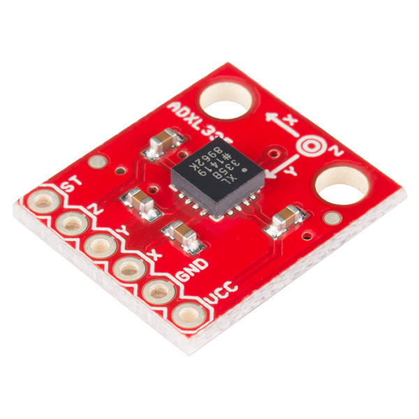
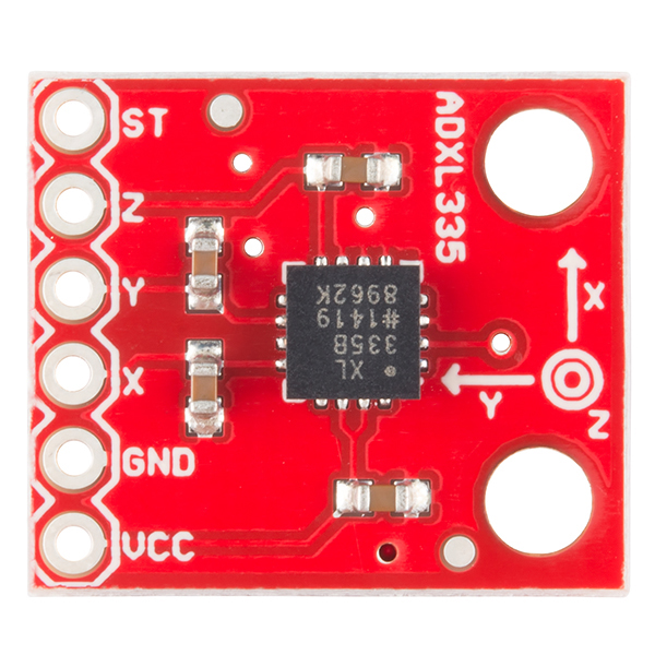
Breakout board for the 3 axis ADXL335 from Analog Devices. This is the latest in a long, proven line of analog sensors - the holy grail of accelerometers. The ADXL335 is a triple axis MEMS accelerometer with extremely low noise and power consumption - only 320uA! The sensor has a full sensing range of +/-3g.
There is no on-board regulation, provided power should be between 1.8 and 3.6VDC.
Board comes fully assembled and tested with external components installed. The included 0.1uF capacitors set the bandwidth of each axis to 50Hz.
Not sure which accelerometer is right for you? Our Accelerometer and Gyro Buying Guide might help!
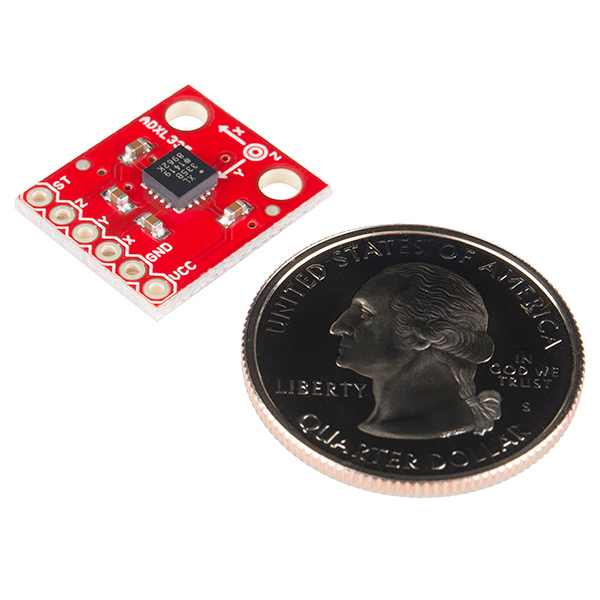
- 0.7x0.7"
- Schematic
- Eagle Files
- Datasheet (ADXL335)
- Wiring Example
- 3D cube project using a PIC
- GitHub
SparkFun Triple Axis Accelerometer Breakout - ADXL335 Product Help and Resources
Das Blinken Top Hat
January 22, 2014
A top hat decked out with LED strips makes for a heck of a wedding gift.
Dungeons and Dragons Dice Gauntlet
August 13, 2013
A playful, geeky tutorial for a leather bracer that uses a LilyPad Arduino, LilyPad accelerometer, and seven segment display to roll virtual 4, 6, 8, 10, 12, 20, and 100 side dice for gaming.
Motion Controlled Wearable LED Dance Harness
January 30, 2019
Control LEDs based on your movement using an accelerometer! Make your LEDs breathe by fading in and out when laying on the floor, turn off the LEDs when moving to your side, or make the LEDs blink in a headstand!
Calibration
To calibrate low-G accelerometers, just use Earth's gravity (1G) for each axis while the accelerometer is at rest. Make sure that each axis is perpendicular to the flat surface that you are using to calibrate the sensor.
Core Skill: Soldering
This skill defines how difficult the soldering is on a particular product. It might be a couple simple solder joints, or require special reflow tools.
Skill Level: Noob - Some basic soldering is required, but it is limited to a just a few pins, basic through-hole soldering, and couple (if any) polarized components. A basic soldering iron is all you should need.
See all skill levels
Core Skill: Programming
If a board needs code or communicates somehow, you're going to need to know how to program or interface with it. The programming skill is all about communication and code.
Skill Level: Competent - The toolchain for programming is a bit more complex and will examples may not be explicitly provided for you. You will be required to have a fundamental knowledge of programming and be required to provide your own code. You may need to modify existing libraries or code to work with your specific hardware. Sensor and hardware interfaces will be SPI or I2C.
See all skill levels
Core Skill: Electrical Prototyping
If it requires power, you need to know how much, what all the pins do, and how to hook it up. You may need to reference datasheets, schematics, and know the ins and outs of electronics.
Skill Level: Noob - You don't need to reference a datasheet, but you will need to know basic power requirements.
See all skill levels
Comments
Looking for answers to technical questions?
We welcome your comments and suggestions below. However, if you are looking for solutions to technical questions please see our Technical Assistance page.
Customer Reviews
4.7 out of 5
Based on 7 ratings:
1 of 1 found this helpful:
You can't solder the chip using an iron
So the BOB is ideal for prototyping.
2 of 2 found this helpful:
Protects an antique clock
I live in California and this little unit along with an Arduino Pro Mini and an airplane servo motor is now an earthquake detector that locks down the pendulum of an antique clock at the first hint of a temblor. Works great.
1 of 1 found this helpful:
Easy to set up and clear support
This tiny board is easy to use, and comes with clear support from Sparkfun. If you need help, just go to the product page and all the information is available, from specifications, to typical wiring connections. This is a basic 3 axis design and can used with your 3 volt arduino projects.
1 of 1 found this helpful:
worked perfectly in near-space
this did exactly what was needed at 90,000 feet and beyond.
wasn't potted, no conformal coatings... not sealed from the elements at all. operated properly from +75°F to -60°F and back in two hours without issue.
highly recommended.
Axis Accelerometer ADXL 335
This is a great sensor! Sparkfun makes it easy to try new sensors out before adapting the technology to your PCB.
Great company - parts, service and Eagle CAD files.
Love this company! Great job guys and gals.
Goodie
Easy to use, analog output accelerometer. Sensitivity is orientation depended, check datasheet and experiment. Screwholes are nice.
sweet
love these packaged chip breakouts... work as expected, good value. I would pay extra if you would offer these with terminals and/or pins soldered on
What kinds of numbers should this thing be putting out? I'm getting stuff in the 700s.
I will note that I ran like 9v through it on accident. When use external reference connected to its VCC pin, I just get zeroes. But when I use internal reference I get numbers in the 700s that do indeed seem to change with my tilt
This is the same width as the Arduino Pro Mini. It would be really amazing if this board were designed so that the holes on one end lined up to A1,A2,A3,VCC,GND holes on one end, and the 2nd, 3rd, or 4th digital pin on the other end, so this could be used as a mini shield.
How do I hook up my wires to the accelerometer? Do I simply loop the copper wire through the holes and twist it back on itself to make the connection?
Soldering wires or pins is best.
The graphic on the board showing the orientation of the x,y,z axis is wrong. I didn't notice this at first but when the Y axis failed I noticed that the x axis didn't respond when I rotated the board around Y. A quick check of the ADXL335 data verified that it is the graphic on the board that is incorrect. It should be rotated 90 degrees so that Y points in the direction X does now.
In the wiring diagram, I noticed that the analog pins are wired directly to the board without a logic level converter (for 3.3V to 5V logic level conversion). I'll be using an Arduino Uno (5V), so I think the analog pins are expecting voltages between 0V and 5V (values 0 to 255). If I don't use a level shifter, that means that the input from the ADXL335 will only be between 0V and 3.3V. So does that mean, I need to calibrate the Uno's sketch to expect a max analog pin value of 168? It would seem this would mean reduced granularity of signal. Is that true?
I know some logic level converter (like BOB-12099) are only for use with digital pins, but I'm assuming one exists that supports analog signals. Any suggestions?
I'm doing a project using the ADXL335 accelerometer from SparkFun. The actual project I'm using P5 and it's working great. I'm running workshops in parallel and want to demo the chip in real-time but am currently out of time to build something from scratch. I'm desperate for a simple processing (or something else) sketch that takes my x, y, z values being printed to the serial port from Arduino and visualizes them in some way. Can anyone point me to anything that won't need a lot of coding time and effort just now?
I'm doing a project using the ADXL335 accelerometer from SparkFun. The actual project I'm using P5 and it's working great. I'm running workshops in parallel and want to demo the chip in real-time but am currently out of time to build something from scratch. I'm desperate for a simple processing (or something else) sketch that takes my x, y, z values being printed to the serial port from Arduino and visualizes them in some way. Can anyone point me to anything that won't need a lot of coding time and effort just now?
I have a question regarding the provided eagle files.
When I load the .brd file into the free version of Eagle, I'm able to see the top and the bottom layers, but am wondering if this board uses more than two layers? The reason I ask, is because the GND pin is not connected to any of the COM pins of the ADXL335
Thanks!
Hi, how can I figure out to connect correctly this accelerometer from sparkfun with a Flora Atmega32u4? I am new to this kind of hobby but I am pretty sure there must be a way to put them together. I am checking the data sheet of both, but any help would be appreciated =)...
Guys im well new to this whole thing and been racking my brain the last few days how to make my accelorometer make my servo arm spin right 180degrees by snapping it forward a bit. Atm its so touch sensitive my servo is doing all kinds of stuff. Any have any ideas?
I to was curious, how do I connect this to my breadboard simply by looping the wires or is some sort of pin/soldering required? Any help would be great!
The best way would be to solder a male pin header onto the board (https://www.sparkfun.com/products/116) and then it would be easy to put on a breadboard. Looping wires through the holes may work, but it would be difficult to keep the wires from touching each other.
linear motion
none
using for keeping a movement horisontally
using and keeping horisontally movement
the accelerator, DDXL335 will be used in one of our scintific experiment at weizmann institute of science, Rehovot Israel. To keep horisontal movement
Is ordered for an experiment task at Weizmann Institute of Science
I used Bildr Example, and as it said, ADXL335 can't have yaw value... But this video below can work! http://www.youtube.com/watch?v=HdApMTRDXes Can anyone kindly show me how to? Thanks a LOT!
Is this accelerometer good for impact sensing?
I'm seeing inconsistent behavior on this model. On 2 separate units, for seemingly no reason, the scaling and offset (volts -> g's) have changed after several days of use. The first unit I did shake fairly hard (more than 3 g's?), but the second unit I was pretty gentle with. Has anyone else seen this behavior?
The cheapest 5V - 3.3V converter on the planet would have to be the red LED. They have a voltage drop of 1.7 volts, so putting a red LED in series with 5V power will let this accelerometer work.
It may be noisier this way for all I know, but it definitely works.
Hi! Does anybody know the mbed code for this accelerometer (ADXL335)? That'd be great! Thanks.
I recently bought this accelerometer but i found that the out put of it on every axis is only about 0.36V or 360mV i have checked with self test pin but it is of no use as there is no change in the output when st pin is connected to vs(3.3V)
if i buy Triple Axis Accelerometer Breakout - ADXL335 .This price $24.95 included the connecter to the computer or not?
if do not included, what connecter using for ADXL335 to connecter to the computer. any link provide for me to buy this connecter
How accurate is this? I need to be able to measure a difference of 0.08 inches in any direction. I know the rule is the lower the measurable g's the more accurate, but how much? I'm going to use this application to place on the end of a gun for dry firing. Any thoughts?
what is the weight of this accelerometer?
I'm looking for the smallest and lightest gyro and accelerometer (digital output or analog) ever in the market (max. 2 gr). I really need it for my MAV.
Is there anybody here can recommend me any with this requirement? Please and thank you...
0.0512 ounces. they are all equally light. look for the smallest breakout board would be my advice.
This is what I was able to accomplish with this board: http://www.youtube.com/watch?v=pN-20mkjZxE.
Slightly noobish question. I'm interested in experimenting with different bandwidths on this chip, which the datasheet says can be selected by placing different capacitances between the x,y,z-outputs and ground. The breakout board comes with 0.1uF capacitors pre-installed, corresponding to a bandwidth of 50Hz. If I wanted to lower the bandwidth, which requires increasing the capacitance, I could just put my own capacitors in parallel with the on-board ones, right? And if I want to increase the bandwidth (lower capacitance), I could put my own capacitors in series with the on-board ones, right? As I understand it, putting capacitors in series will change the overall working voltage of the circuit -- won't this complicate my interpretation of the accelerometer output? i.e., the 0g voltage level, and volt/g response will no longer be as described in the datasheet? Could I damage the chip?
Right out of the package, I stupidly hooked this up to 5V for a minute or so. I switched back to 3.3V, and now all I get are pseudorandom numbers from the device. Did I kill it?
Probably.
damn that's big
I don't think that's correct. Move the decimal one place to the left and you should have the correct measurements.
No. Your dimensions are 10 times larger than shown clearly in the photo above.
Did you even read the comment?
Could someone please give a few examples of typical applications in the +/- 3g range? Thanks!
Sure, automotive. Datalogging for cars on track, to be specific. It's not unheard of to hit 3g in braking, turning, bumps...just usually not acceleration.
Also, robotics...
What about... helicopter yaw correction?
This is a pretty standard accelerometer. You get all three axis with +/- 3g range. Yes, the silkscreen is wrong for the x and y axis (at least mine was), but who looks at that anyway? The ADXL335 chip is used pretty commonly in other IMU applications due to its simplicity
How do you properly secure this on the chassis/board of the robot?
I'm thinking about ordering one, I have 2 ideas on how to fixate it, but they are both meh.
You guys should either get that wiring example updated, or unlink from it - it shows 5V, when it's a 3.3V device.
Yes, you are correct. It should be the 3.3V line and not the 5V line.
I am getting confused.
In the text they say use the voltage between 1,8 and 3,6 VDC.
In the Schematic stand 5 V DC
What to use?
The operating voltage should be between 1.8v and 3.6v
The X axis of my accel just died... just like that... i was reading the voltage values with a multimeter and suddenly X reads 0 V (marked as Y on BOB)
I tried with the self-test pin but it's completely gone... the other 2 axis work fine... has anyone else had this problem??
Try sending an email to Sparkfun if it's that bad. I'm sure they can help. Maybe even ask if they can make an ADXL335 accelerometer tutorial
Does this breakout include the accelerometer? I am new to this stuff and am having trouble understanding all the breakouts and evaluation board nomenclature.
Yup, comes with everything shown in the pics, well, minus Mr. Washington. All components will be populated.