- Home
- SparkFun O-Clock - AVR Oscilloscope Clock

SparkFun O-Clock - AVR Oscilloscope Clock
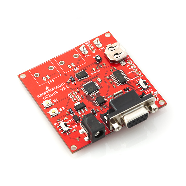
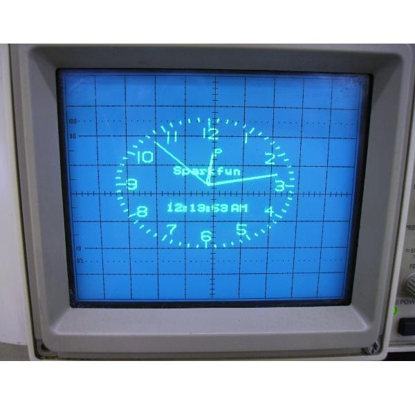
The SparkFun O-Clock can convert your X-Y analog oscilloscope into an analog clock or terminal. In addition, it can be used alone as a function generator. It is very similar to the AVR Oscilloscope Clock Kit, but this board is all SMD and comes fully assembled.
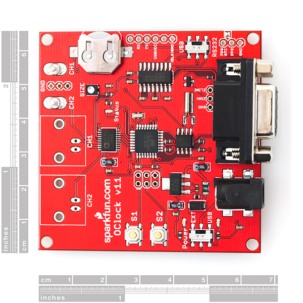
The O-Clock is based around an ATmega328 which is interfaced with a DS1307 RTC module and an AD7302 DAC. A cell battery backup is provided so the clock won't lose its time. The oscilloscope can be connected to the O-Clock through BNC connectors (not included) or by probing the CH1/2 turrets.
Time and other options can be set using the on-board momentary push buttons, or through the RS-232 interface. A 0.1" pitch header provides access to the UART of the ATmega to allow for an optional USB interface using our FTDI Basic Breakout. GPS modules or other external PPS signals can be connected to serve as an external clock.
The updated firmware found in the Documents section below is loaded with features. There are 37 display combinations to choose from. You can even use the O-Clock in terminal, or function generator modes. In addition, a bootloader allows for easy firmware uploading.
The terminal application can support persistent vector graphics for creating and displaying games, like Asteroids, on other computers.
Power can be provided by USB or an 8-15VDC supply to the center-positive 5.5x2.1mm barrel connector.
Note: Power supply and BNC connectors are not included, see related related items.
If you have the older kit and are looking for more information, it can be found here.
Features in Firmware V4.1:
- New on-screen menu
- Control burn-in protection frequency from 1-9 minutes
- Vector graphics mode for games like Asteroids
- Supports 250,000 baud value
- GPS mode remembers serial port speed setting
- Help screen
- Alarm clock
- New clock face
- LED shows time in Morse code
- Function generator 1 cycle faster
- Use the IOCTL command to select unusual options
- Support for 2015-2021 with automatic Daylight Saving Time corrections
- Connects to your X-Y analog oscilloscope via probes or BNC connectors.
- Two momentary push buttons to navigate through on-screen menu
- RS-232 interface (optional USB interface through serial header)
- 0.1" pitch header for external clock signal (GPS 1PPS, Rubidium Oscillator, etc.)
- 37 display combinations
- Display calibration mode
- Intensity control
- STK500v1 compatible bootloader
- On-board Real-Time Clock IC with 32.768kHz crystal and battery backup: this clock won't lose time!
- Optionally add a User Name to the Clock Display
- Automatic Time and Date setting when connected to the NMEA output from a GPS device (TTL level serial connection)
- Terminal and function generator modes
- Demo and Fun modes
- Automatic Daylight Saving Time correction for 2008-2014 for the USA and the EU
- Clean Reset of the EEProm Configuration Data option
- Schematic
- Eagle Files
- Firmware v4.3 (updates the Automatic Daylight Saving Time period of 7 to 2021-2027)
- Dutchtronix O-Clock Homepage
- Source Code
- Operating Instructions
- FAQ
SparkFun O-Clock - AVR Oscilloscope Clock Product Help and Resources
Core Skill: Soldering
This skill defines how difficult the soldering is on a particular product. It might be a couple simple solder joints, or require special reflow tools.
Skill Level: Noob - Some basic soldering is required, but it is limited to a just a few pins, basic through-hole soldering, and couple (if any) polarized components. A basic soldering iron is all you should need.
See all skill levels
Core Skill: Programming
If a board needs code or communicates somehow, you're going to need to know how to program or interface with it. The programming skill is all about communication and code.
Skill Level: Rookie - You will need a better fundamental understand of what code is, and how it works. You will be using beginner-level software and development tools like Arduino. You will be dealing directly with code, but numerous examples and libraries are available. Sensors or shields will communicate with serial or TTL.
See all skill levels
Core Skill: Electrical Prototyping
If it requires power, you need to know how much, what all the pins do, and how to hook it up. You may need to reference datasheets, schematics, and know the ins and outs of electronics.
Skill Level: Noob - You don't need to reference a datasheet, but you will need to know basic power requirements.
See all skill levels
Comments
Looking for answers to technical questions?
We welcome your comments and suggestions below. However, if you are looking for solutions to technical questions please see our Technical Assistance page.
Customer Reviews
4.4 out of 5
Based on 7 ratings:
Why too easy!!
Straight out of the box, power up and it just works. Waiting for source code so I can break this thing....
Flakey Junk
I had hoped that Sparkfun had better quality control. Not so, cold solder joints plague this board with its intermittent operation draining my valuable time. No time to argue with Sparkfun on this, it has taken enough of my time. If Sparkfun would like to send me a working replacement, that would be nice but meanwhile please save yourself time and money and avoid this.
Sorry about your issues. We have a number of tests and inspection steps in our production process to avoid bad units getting out. However, sometimes a troublesome board can sneak past our processes. We don't want to argue, if your board is having issues all you need to do is contact Sparkfun Technical Support and we'll be happy to get that back for inspection and replacement. Thanks
Works straight out of the box-- fairly crisp display, even with a 1950s Eico 460 oscilloscope with limited bandwidth.
Surprising amount of customization and mode options-- multiple clock faces and apps (e.g. text terminal) ensure that it's not just a one-trick pony.
Open source, so it's as much a learning opportunity as a gadget.
Very neat little board.
It's simple to connect but wish it was an older style kit form - love to build electronics. After I installed the 2 BNC jacks, it was placed in a small ziplock bag to keep it clean and it's unnoticeable.
Worked out of the box on 20Mhz B&K dual trace scope
Everything worked great using the probe turrets, but you need to ensure each probe is grounded to the PCB's ground or you will not get a properly sync'd picture. I used the GND pins located between the turrets to clip the probes to, but wish they had easier locations. Also ensure your probes are properly compensated with your scope's test clip prior to hooking to the PCB for best picture/geometry.
This is - first of all - working exactly as expected.
So, that's great. I tested it on a scope in x-y mode and it's working. My final implementation is dependent on hacking into the x and y amps on some video test equipment that was being discarded from my workplace. The good news there is that I found complete documentation on that gear so I feel confident that will all work out once I get a chance to get at it.
Does this run with a 16 MHz crystal or 20 MHz? Also what is the value of the trim pot U4? Can't find any kits available so I'm breadboarding one... Thanks, - Steve
The crystal is 20MHz and U4 is 10K. :-)
Plus one from me please. I also missed ordering this, and I am not really up to sourcing a board and parts at this time. I would also buy one if they came back.
If anyone else here is making one, email me at orubin at gmail dot com. I would like one as well.
Is there any way at all that sparkfun will make some more of these boards
I missed the boat the first time round and would dearly love at least three of these
I can't be the only one :-)
Great site and a great company thanks
just heard some of you over on an old "Amp Hour" episode
keep up the good work
regards
adrian
I don't think we will be making any more, but we do have the Eagle files posted above for any user to make their own. PCB fab houses like OSHPark are really beneficial for small runs like that. Sorry about that!
Thanks for this very fine product. It works very well. Congratulations to the designer.
Is the firmware for this open source and available?
Yes, the firmware is open source and should be posted on the Dutchtronix homepage very soon.
This is very neat, works with my old 35 MHZ oscilloscope. Wish one is developed for a Vectorscope. (external device so no modifications to vectorscope required).
This clock board will work quite nicely with some of the student model kit oscilloscopes which otherwise would not be usable given their limitations.
I built mine into a Bell & Howell (Heath) solid state student model scope and it works quite well after about a 30 minute warmup period. One thing though. Had to remove the green filter in order to use the whole CRT face.
Just bought my 5th. I add these internally to old scopes from eBay that I either sell or give as gifts. In your office it really makes for a conversation piece.
Very nice.
By far the best scope I have found for the clock is a Bell and Howell (Heath) model 10D-203-31 student model oscilloscope. With this particular scope it MUST have all the electrolytic capacitors replaced, the paper caps in the CRT power supply replaced and also the internal adjustment pots replaced in order to have any kind of reliability and stability of the adjustments. Also removing the green filter allows the full CRT face to be used.
I bought a cheap, old 'scope and found that the O-Clock output was mirrored. I had no luck finding a suitable hardware solution so I tackled changing the firmware to invert the X-channel voltage. It turned out to be just a couple of lines. Details and photos in this flickr set
I just received two more. That makes three otherwise junk-bound old scopes converted to a cool item and two board to continue experiments. It must be a couple years ago I asked the software author for a special version to slow down the display drawing rate via a numerical command and received it (thank you!), and am still working on doing the clock with an electromagnetic display. As many know, they are slow and require power amplifiers with current feedback to drive the inductive load of the deflection coil, but there is nothing like a TV set or computer monitor conversion because of the nice large screen. The black and white TV sets are the easiest to work with because of no convergence issues, but at this point I can see that I have to rewind the yoke to lower its inductance to 1mH or less for the speed. That is the state of affairs. Volume 22 of the MIT radiation laboratory series (displays) shows how to wind a yoke of various types, perhaps a lost art. "the secret life of XY monitors" online provides amplifier schematics. So, not it is not done yet but I am getting closer and of course learning far more than I had ever expected. Please keep supplying these boards!
I have an older engine analyzer with a CRT that from what I found online was used in vector monitors. I already know where to input the signal to the vertical and horizontal deflection amp cards.
Will the slower drawing rate version of the firmware work on that display? If so how can I get a copy of it?
I'm trying to connet the clock to a XY laser scanner system so I need the reduced displey drawing rate too. Any chance to get it? Could you please kindle send it to asdfgh_1950@libero.it Thanks
I've just written a short article about using this with a digital scope:
http://www.scopejunction.com/author.asp?section_id=1835&doc_id=257129
I bought one of these but I'm not sure if my scope is compatible - can anyone tell me if this should work with a Scopex 4D10? Manual is here - http://www.vintage-radio.net/forum/attachment.php?s=e5f95a5d48a989bdc88ebe58a7230fff&attachmentid=55675&d=1314554947
With a 500KHz Horizontal amp, the answer is "maybe". Can you use one of the vertical channels as an H input?
The only way to find out is to try it.
Regarding:
"Without blanking: http://ragelse.com/i/fOb72Nh With blanking connected: http://ragelse.com/i/SqS82Nh " one thing annoying is the polarity of the blanking. In some cases it needs to be inverted. This means, not logically inverted, but electically inverted. In other words, the states from theboard are 0 and +3.3V. But a -3.3V(or whatever) is needed to get blanking on some scopes.
The Z axis of a scope, if DC-coupled, is meant to be blanked by a voltage below zero and intensified by a voltage above zero. So, you need a negative supply rail and an inverting amp. A transistor or two should do.
A comment on the image with no blanking: the deflection amplifier speed on that scope might be a bit slow.
This board requires a fast scope, it is unfortunate but at very least 2MHz. If the DAC could hold for a longer time after each 'point' was plotted, the slower scopes can be more easily used.
I hope this kit will continue, and I hope some documentation canbe created by programmers for the firmware. I do not understand software, need everything commented. I would like to see a possibly simpler rendering using less points, that could be easier on some of the oddball scopes people are trying. Anyway i am very happy with these kits, and I hope my comments on blanking helped you.
I've used this on several different older scopes (mostly vacuum tube operated) and it works well EXCEPT on scopes that use single ended deflection amps such as a scope that uses a 3AP1 CRT. That said even though those scopes do not go to 2 MHz I don't know how high in frequency the deflection amps can handle.
I'm having a bit of a problem with the Z output. I have built a XYZ monitor out of an Tek waveform monitor which uses a scope CRT. I have built deflection amps after this schematic: http://www.electronixandmore.com/project/7.html and it works great!
The instrument originally had a Z-input from the main processor, and it's current-controlled. I added a NPN transistor with 825 ohm in series, this is what the apparatus originally used for blanking/drawing. Controlling the transistor from my signal gen works just fine, i can get good blanking on the CRT.
Without blanking: http://ragelse.com/i/fOb72Nh With blanking connected: http://ragelse.com/i/SqS82Nh (sorry for the shaky picture)
Connecting the ZLINE og ZINV to my transistor, i get a strange picture. With my transistor, the beam is active high, so i need to use the ZINV output on the board, but the picure is wrong. I can see the image, but maybe only 20% of the segments are legible, like the signal on the Z channel is a bit off in timing. I don't have any other scope with a Z input that i can test this on, any advice on my problem here ? Thanks!
I use a Tektronix 606A X/Y monitor and had a similar problem. You will need to attenuate the ZINV output. Best way to do that is use a variable resistor of 10K or higher or lower (depending on the input impedance of the Z axis circuit) and set it until the picture looks proper. You can then measure the variable resistor and install a couple fixed resistors.
I would like to use the clock with a circa 1968 TEK 321A (a very cute portable scope that can run on 10 D cells), which inverts the external sweep input signal. Is there any way, short of a sw mod, to invert the ch1 signal coming out of the clock board? Thanks...
I laid out a board for BatchPCB manufacturing that will drive a small CRT based on the Jon Stanley design - it's claimed to work well with this clock. If anyone's interested I will make it public on BatchPCB (around $30 for single quantities) along with the BOM of materials from Digikey to solder onto it (another $20ish) - Then add a Hammond 270X transformer (~$45), and a CRT of your choice: Sphere Research in British Columbia has lots of good choices that should work well with this setup such as the 3RP1-A, which I've successfully used in a different design.
I plan to make one please
send info on board and bom
Richard Friedrich
rfriedrich@suddenlink.net
OK, I've got my first board back and the circuit is working well, although I've got a few kinks to work out so the board will need a revision before I unleash it on the public.
1: Minor layout errors: 1 5vAC input was not connected to the rest of the circuit, easily fixed with a wire.
2: DIPTrace had lead numbers reversed for the ZTX458 and the +/-5V regulators. Easily fixed by desoldering and turning the parts around, but this needs to be fixed to avoid magic smoke release for future users.
3: The 150ma 7805 output is sagging for some reason to under 3V when attempting to power both the onboard TL082 op-amp and the O-Clock board via the USBVCC 5V input. I don't quite understand why, there ought to be plenty of current capability remaining, so this needs further investigation. An alternative is simply to power the O-Clock separately from the CRT board via a wall-wart and its barrel jack, which is how I have it working now. This requires further investigation - I'm not an EE, so it's probably something obvious, but at the moment I don't quite get it. If anybody would like to help, I'm happy to send my schematic. :-)
Kinks have been worked out. All leads are in the proper place relative to the silkscreen, and the voltage multiplier which provides sufficient dropout headroom for the 5V regulators has been redesigned with 1000uf caps, which I verified resolves the current limitations with the previous 100uf design - you can now power the whole thing, CRT, o-scope and all, from a single AC transformer. This board has been uploaded to BatchPCB for you to have manufactured for yourself at this link.
I'm definitely interested. I've used Jon Stanley's design with great results, and have had a few requests to replicate the circuit.
I got a question. I want to add a series resistor to the X/Y outputs to protect them from accidental shorts. What is the smallest value resistor that I can use without affecting the display and that will not allow too much current through the chip if the output gets shorted to ground? I connected the clock to a scope and somehow shorted one output. Now the clock don't work right.
Tyco Part# 5227161 BNC connector please? I'm surprised it's not populated (would make it much easier)... but awesome product as always!
I have noticed a problem. On my clock whenever it is in PPS 1Hz mode the clock jumps from 0 to 1 seconds in less than a second which makes the clock gain a few seconds in under an hour. Now if I use PPS 4096 mode it don't do that. Is there a way to fix it as I don't want to have to select PPS 4096 mode each time I power up the clock. I have the latest firmware installed as well.
The PPS 4096 mode is persistent, meaning that once you change it, it stays that way, even after you turn the clock off. I just verified this. I don’t quite understand your other problem (jumping from 0 to 1 seconds in less than one second). Maybe you can contact me at jan at dutchtronix dot com
-Jan-
(firmware author)
Works great! Took about a minute to get it working on my Tek 2236 -- even works fine on my low-end 20mhz Global Specialties "orphan" scope. <br />
<br />
The issue of whether to include BNC connectors with the board is an open one, and bears on the intended use. The BNCs add a lot of (possibly unnecessary) bulk to a compact design. Of course, one could make the same argument about the DB9 header, and to a lesser extent, the power connector. I think Sparkfun has drawn the line reasonably.<br />
<br />
Thanks for putting this together, Sparkfun! (I'm getting me another one...)
Do you plan on selling the Tyco Part# 5227161 BNC connector? That would be a lot easier. $2.10 from Mouser plus shipping... when I place a lot of orders from SF. A nice enclosure would be nice too (but I know that's asking too much). Thanks.
cool! now all I need is an analog o-scope. :)
I love the clock, but I need some slower bauds rate for the terminal. Where can I get a copy of the source for the firmware, I can't seem to find it? Thank!
PS. using a tek 468 osilloscope
You can change the baudrate using the menu.
The source code is posted on this page:
http://www.dutchtronix.com/ScopeClockH3-1-Enhanced.htm
jrseattle