- Home
- Product Categories
- LCDs and OLEDs
- Color LCD Shield

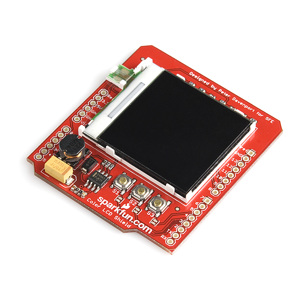
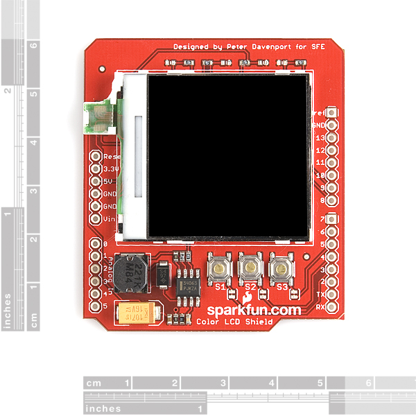
Color LCD Shield
Replacement: None. We are no longer carrying this LCD shield in our catalog. This page is for reference.
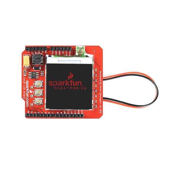
The Color LCD Shield, recommended by and designed in partnership with an SFE customer, provides an easy method of connecting the popular Nokia 6100 LCD to your Arduino. The board comes as shown with the 128x128 mini color LCD, as well as a backlight driver circuit (boosts to 7V), and three momentary push-buttons (tied through a jumper to pins D3-5).
The Nokia 6100 LCD is controlled through a 9-bit SPI interface. The control pins of the LCD are connected to the hardware SPI pins of the Arduino (D13 -SCK, D11 - DIO), the CS pin is tied to D9 and the reset pin is connected to D8. Voltage from the '5V' pin of the Arduino is boosted to 7V to power the LCD backlight.
The Nokia 6100 LCD is included with the Color LCD Shield. Headers are not soldered on, we recommend the 6 and 8-pin stackable headers.
Note: This shield uses the Epson S1D15G10 or Philips PCF8833 controller (we cannot guarantee which one you will receive. Please see Jim Lynch's tutorial below as to why.
Note: This product is a collaboration with Peter Davenport. A portion of each sales goes back to them for product support and continued development.
- Schematic
- Eagle Files
- Quickstart Guide
- Color LCD Shield Arduino Library
- Example C Code (ATmega328)
- Example Arduino Library (Thanks Peter!)
- Example Arduino Code (Thanks Mark!)
- Tronixstuff Tutorial
- Interface tutorial by Jim Lynch
- GitHub (Library)
Color LCD Shield Product Help and Resources
Core Skill: Soldering
This skill defines how difficult the soldering is on a particular product. It might be a couple simple solder joints, or require special reflow tools.
Skill Level: Noob - Some basic soldering is required, but it is limited to a just a few pins, basic through-hole soldering, and couple (if any) polarized components. A basic soldering iron is all you should need.
See all skill levels
Core Skill: Programming
If a board needs code or communicates somehow, you're going to need to know how to program or interface with it. The programming skill is all about communication and code.
Skill Level: Competent - The toolchain for programming is a bit more complex and will examples may not be explicitly provided for you. You will be required to have a fundamental knowledge of programming and be required to provide your own code. You may need to modify existing libraries or code to work with your specific hardware. Sensor and hardware interfaces will be SPI or I2C.
See all skill levels
Core Skill: Electrical Prototyping
If it requires power, you need to know how much, what all the pins do, and how to hook it up. You may need to reference datasheets, schematics, and know the ins and outs of electronics.
Skill Level: Rookie - You may be required to know a bit more about the component, such as orientation, or how to hook it up, in addition to power requirements. You will need to understand polarized components.
See all skill levels
Comments
Looking for answers to technical questions?
We welcome your comments and suggestions below. However, if you are looking for solutions to technical questions please see our Technical Assistance page.
Customer Reviews
No reviews yet.
Hi, can someone help me? I've been trying to display the clock program that this site gives us but when I verify it it says:
Arduino : 1.6.9 (Windows 7), Carte : "Arduino/Genuino Uno"
sketch_oct19a:23: error: 'LCDShield' does not name a type
LCDShield lcd;
^
C:\Users\tdonxaya\AppData\Local\Temp\arduino_modified_sketch_585386\sketch_oct19a.ino: In function 'void setup()':
sketch_oct19a:44: error: 'lcd' was not declared in this scope
lcd.init(PHILIPS);
^
sketch_oct19a:44: error: 'PHILIPS' was not declared in this scope
lcd.init(PHILIPS);
sketch_oct19a:17: error: 'BLACK' was not declared in this scope
#define BACKGROUND BLACK // room for growth, adjust the background color according to daylight
C:\Users\tdonxaya\AppData\Local\Temp\arduino_modified_sketch_585386\sketch_oct19a.ino:46:13: note: in expansion of macro 'BACKGROUND'
lcd.clear(BACKGROUND);
C:\Users\tdonxaya\AppData\Local\Temp\arduino_modified_sketch_585386\sketch_oct19a.ino: In function 'void displayDigitalTime(int, int, int, int)':
sketch_oct19a:185: error: 'lcd' was not declared in this scope
lcd.setStr(timeChar, CLOCK_CENTER + CLOCK_RADIUS + 4, 22, C_COLOR, BACKGROUND);
^
sketch_oct19a:18: error: 'RED' was not declared in this scope
#define C_COLOR RED // This is the color of the clock face, and digital clock
C:\Users\tdonxaya\AppData\Local\Temp\arduino_modified_sketch_585386\sketch_oct19a.ino:185:61: note: in expansion of macro 'C_COLOR'
lcd.setStr(timeChar, CLOCK_CENTER + CLOCK_RADIUS + 4, 22, C_COLOR, BACKGROUND);
sketch_oct19a:17: error: 'BLACK' was not declared in this scope
#define BACKGROUND BLACK // room for growth, adjust the background color according to daylight
C:\Users\tdonxaya\AppData\Local\Temp\arduino_modified_sketch_585386\sketch_oct19a.ino:185:70: note: in expansion of macro 'BACKGROUND'
lcd.setStr(timeChar, CLOCK_CENTER + CLOCK_RADIUS + 4, 22, C_COLOR, BACKGROUND);
C:\Users\tdonxaya\AppData\Local\Temp\arduino_modified_sketch_585386\sketch_oct19a.ino: In function 'void drawClock()':
sketch_oct19a:196: error: 'lcd' was not declared in this scope
lcd.setCircle(CLOCK_CENTER, 66, CLOCK_RADIUS, C_COLOR);
^
sketch_oct19a:18: error: 'RED' was not declared in this scope
#define C_COLOR RED // This is the color of the clock face, and digital clock
C:\Users\tdonxaya\AppData\Local\Temp\arduino_modified_sketch_585386\sketch_oct19a.ino:196:49: note: in expansion of macro 'C_COLOR'
lcd.setCircle(CLOCK_CENTER, 66, CLOCK_RADIUS, C_COLOR);
sketch_oct19a:17: error: 'BLACK' was not declared in this scope
#define BACKGROUND BLACK // room for growth, adjust the background color according to daylight
C:\Users\tdonxaya\AppData\Local\Temp\arduino_modified_sketch_585386\sketch_oct19a.ino:201:64: note: in expansion of macro 'BACKGROUND'
lcd.setStr("12", CLOCK_CENTER - CLOCK_RADIUS, 66-9, C_COLOR, BACKGROUND);
C:\Users\tdonxaya\AppData\Local\Temp\arduino_modified_sketch_585386\sketch_oct19a.ino: In function 'void displayAnalogTime(int, int, int)':
sketch_oct19a:230: error: 'lcd' was not declared in this scope
lcd.setLine(CLOCK_CENTER, 66, CLOCK_CENTER+sx, 66+sy, BACKGROUND); // delete second hand
^
sketch_oct19a:17: error: 'BLACK' was not declared in this scope
#define BACKGROUND BLACK // room for growth, adjust the background color according to daylight
C:\Users\tdonxaya\AppData\Local\Temp\arduino_modified_sketch_585386\sketch_oct19a.ino:230:57: note: in expansion of macro 'BACKGROUND'
lcd.setLine(CLOCK_CENTER, 66, CLOCK_CENTER+sx, 66+sy, BACKGROUND); // delete second hand
sketch_oct19a:21: error: 'YELLOW' was not declared in this scope
#define S_COLOR YELLOW // second hand color
C:\Users\tdonxaya\AppData\Local\Temp\arduino_modified_sketch_585386\sketch_oct19a.ino:238:57: note: in expansion of macro 'S_COLOR'
lcd.setLine(CLOCK_CENTER, 66, CLOCK_CENTER+sx, 66+sy, S_COLOR); // print second hand
sketch_oct19a:20: error: 'GREEN' was not declared in this scope
#define M_COLOR GREEN // minute hand color
C:\Users\tdonxaya\AppData\Local\Temp\arduino_modified_sketch_585386\sketch_oct19a.ino:243:57: note: in expansion of macro 'M_COLOR'
lcd.setLine(CLOCK_CENTER, 66, CLOCK_CENTER+mx, 66+my, M_COLOR); // print minute hand
sketch_oct19a:19: error: 'BLUE' was not declared in this scope
#define H_COLOR BLUE // hour hand color
C:\Users\tdonxaya\AppData\Local\Temp\arduino_modified_sketch_585386\sketch_oct19a.ino:251:57: note: in expansion of macro 'H_COLOR'
lcd.setLine(CLOCK_CENTER, 66, CLOCK_CENTER+hx, 66+hy, H_COLOR); // print hour hand
exit status 1 'LCDShield' does not name a type
Ce rapport pourrait être plus détaillé avec l'option "Afficher les résultats détaillés de la compilation" activée dans Fichier -> Préférences.
Sounds like the library for the shield is not installed correctly. Try thistutorial and if you still have problems please email our techsupport team.
CAUTION: Do not use with the Arduino Pro - 5V !
The 3.3 v output is tied to the 5v output!
You WILL damage your lcd if plugged in to one of these Arduinos
TheMoogle's comment really worried me initially. I now understand the issue better and wanted to clear it up for anyone else who might be confused.
Basically, the Arduino Pro does not provide two distinct voltages on the two voltage lines. The 3.3V Pro wouldn't be able to provide 5V without a step-up, so it simply ties the lines together, and puts out 3.3V on the 5V line. The 5V Pro uses the same PCB, and so it winds up putting out 5V on the 3.3V line. This is one of those limitations of the Pro that owners need to be aware of.
I own a Duemilanove and so, prior to understanding this issue, I was very concerned about whether I ought to be ordering this item. To clarify: this is only a problem for the 5V version of the Pro and similar boards. The shield should be fine with the 3.3V Pro (since 3.3V is still enough voltage for the step-up circuit) and it should be fine with any full-featured Arduino models like the Duemilanove. It's not an issue with this shield at all - it's just a consequence of Pro's simplified design. I think you have to be careful in general of what shields you plug into a 5V Arduino Pro...
TheMoogle - Throughout prototyping this LCD was tested on a 5V Arduino Pro. Yes, this is "out of spec", however my LCD is still alive and doing its thing. I don't know to be honest; running it at 5V probably will shorten the LCD's lifetime.
skystorm - 3.3V will definitely work just fine for the step-up circuit.
And if You connect to Arduino Pro - 3.3V
the 5v output will be tied to 3.3V.
Will 3.3V enough for voltage booster???
Perhaps in a future revision the board could include a reset switch? Since this is one of those Arduino shields that has to be on top, it could be handy. (In the mean time, I suppose one could cut a trace and wire a jumper in order to turn one of the existing buttons into a reset switch...)
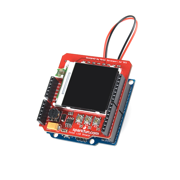
The red and black wires are wires to a battery used to power the arduino and shield.
To boost the brightness i think that you will need to mess with the"
LCDCommand(VOLCTR); // electronic volume, this is the contrast/brightness(EPSON)
//LCDData(0x18); // volume (contrast) setting - fine tuning, original
LCDData(0x24); // volume (contrast) setting - fine tuning, original
LCDData(0x03); // internal resistor ratio - coarse adjustment
LCDCommand(P_SETCON); // Set Contrast(PHILLIPS)
LCDData(0x30);" code in LCD Driver.c
Does anyone know what the red and black mystery wires are? It looks like those are for the LCD backlight driver circuit? I am guessing. I can get Mark's code to run, but it is very very dim. It is kind of crazy to sell an Arduino shield without any documentation or Arduino-specific code.
Any ideas how to boost the backlight?
Thanks.
1st error is "multiple definition of 'delay_ms'"
2nd is "multiple definition of 'LCDData'"
Some information, I'm using the Arduino Duemilanove ATmega 328
To anyone else who has this error it is caused by having duplicated files one in the sketch folder and one in the libraries folder. To solve the problem delete LCD_driver and nokia_tester in the sketch folder.
Hey! anyone have worked with this shield? I tried the example arduino code by mark but there seems to be alot of error. Mostly duplicated functions in the LCD_driver.c portion. Anyone can help me with it?
I got Mark's Arduino code working with the breakout board version of this.
Can you be more specific about what errors you're getting?
Interesting that this is an Arduino shield but there don't seem to be any/many apps or examples written to run this display on the Arduino. The example code is written in C++, and I'm not sure how to run this on a vanilla Arduino system...
Yeah...no Arduino sketch yet. You can still load the example code using the Arduino bootloader though. Check out the 'Serial bootloading an Arduino board' section of our STK500 tutorial.
How can I get this part?where can i buy it? I need your help.
I bought this shield for displaying text. The one I received is probably an Epson, since trying code with Philips only shows a black screen. Problem is that the text is distorted, I can vaguely indentify the size of the words, but not individual letters. This is with the lcd.setStr() function. It is possible to draw a circle with a line. What can be wrong?
i want to use the library´s Peter but i can not use it, i want to do the O-scope that is in this example please somebody help me mi email is jcvelasco@uniboyaca.edu.co
hello guys i need your help i have to do a project for my class in the college i need to graph a imagen in this lcd but i dont know how can i do it i saw the example in the library but i can not modify it thanks
hey guys i am new in the excelente page
i need you help ¡¡¡ i need to graph an imagen in the lcd color in arduino, and i dont know what is the procedure thanks fot your colaboration
I would like to use this on my Arduino Due.
The problem is, I do not know how much it outputs to the arduino pins, because the Due only supports up to 3.3v, and I am worried this will output more than that. Can someone please tell me how much this board outputs?
Hello,
I try to use TestPattern program in Example Arduino Library form Peter, and I have an error after compilation :
In file included from /Applications/Arduino.app/Contents/Resources/Java/hardware/arduino/cores/arduino/Arduino.h:213, from LCD_driver.c:27: /Applications/Arduino.app/Contents/Resources/Java/hardware/arduino/variants/standard/pins_arduino.h:43: error: expected identifier or '(' before numeric constant
Arduino Uno with Sparkfun color LCD shield
Thanks for assistance
Didier
HI everyone ! I have a Color LCD shields and arduino uno. I wanted to load a logo like sparkfun logo in sample code. So can any one suggest how to do so ?
Just wanted to mention that the official Arduino ColorLCDShield library does not work with the Arduino Due but the gLCD-Library by TCWORLD works great! ;-)
Is it just me or are the buttons stupidly sensitive? I've been using the Bounce library to try and de-bounce them but they still register inputs if I bump the board, and always register well before I feel the tactile "click". Anything I can do to fix this?
I don't have this product so I wouldn't know for sure about the sensitivity. (I'd probably hook up external buttons anyway).
However, just to make sure of one step, did you enable the internal pull-ups on the 3 pins used by the buttons?
Otherwise you may have to delve into the debounce code in question and make it more robust still for this particular application.
That was it. Good call! :)
Cool! Glad I could help :)
what is function of resistor R13? what if we dont use R13 resistor and directly short 5v to lcd backlight pin??
Is anyone still having high pitch noise coming off of the booster coil? I didn't think much of it until I could not get reliable analog reads from the analog pins. I discovered that the booster coil induced noise into the analog pins due to proximity. If you have a shield with a high pitch booster circuit then attach a 10mF capacitor across the 5v supply as close to the shield(if not soldered on)as possible to get rid of the hum.
Has anyone tried this outside? I am looking for a display I can put on my Motorcycle to show Gear, Voltage, Current and anything else I can think off.
You could use this outside, but you'd need to have your set up encased in something. These screens/shields are not weatherproof.
Yah I have plans to encase it to weather proof it. My concern is the sun washing it out. I live in Arizona and the sun us harsh on stuff out here. Don't need it going blank after 5min in the sun/heat.
Hi Toni_K, Well it appears that the github for the LCD Shield is read only for me. So I will email the files soon so you folks can update the library.
Thanks, Tony...
I am working on a software update with additional features to the Color LCD Arduino Library. My question is where should I submit the updated library files?
Thanks, Tony
Hi Tony! The best place to submit new library updates would actually be through the library Github page, available here. If you don't have an account or can't create one, you can always send them to techsupport@sparkfun.com and we can make sure they get to the proper people. Thanks for sharing!
Are there mechanical drawings available? I need to put this in an enclosure (with the Arduino board). I am looking for specific dimensions.
Thanks,
I have to agree with several of the comments below. This item is sub standard for what I have come to expect from Sparkfun. In my case, I'm running attached to a uno. The examples work, but there are garbage or noise lines all over the screen. They get worse as time goes on. I think it's probably a damaged display and not the code. Can anyone recommend a better ( more reliable ) shield with a display. I'm not picky, monochrome is fine for what I'm doing.
Ok. So im an engineering student getting used to arduino and picked up this shield.to play with. After an hour i got it to display 8 lines of random generated data. Next I used that code to update an existing program which controles a dc motor and propeller to achieve some desired life using a pid... Silly me though I forgot to check and see if a pin is being shared or not, one was and as a result my uno is messing up calling an avdr error, i believe that my serial port is fried though I could be wrong. So i fixed the code and tried it on my mega and it worked fine for a few hours of use. Then I got random characters showing and now the lcd is not showing anything at all, after just 4 hours of use. My question is what could cause it to fail? Also i soddered pins 2,3,4,5,8,9,10,11,12,13,gnd(top right),the teo gnds on the left, and the 5 and 3.3 volt pins. Is this excesive or nessicary. It looked like the schematic called that these are used.
This may seem like a stupid quesition but how do you use the buttons? They are wired to connect the arduino pins to ground when pressed. The standard way to use a button is to wire the pin to ground via a resistor and run +5V to the pin from the button, pulling the pin to HIGH when the button is pressed. For this board do I need to run +5V to the each pin to pull them HIGH by default and let the button pull them to LOW? Am I missing something?
What you might be missing, is that the Arduino has internal pullup resistors that can be enabled/disabled on each digital input. By connecting a switch to ground, and turning on the internal pullup, you can save an external resistor.
Does anyone know where I can find a library for this screen that has a wrap or scroll feature for text, so that when I send the screen a char array it will drop every 15th character to the next line?
In the latest version of my library (https://github.com/TCWORLD/gLCD-Library) I have fixed a bug in the printing fuction which means that the '\n' character now moves to the next line on the screen (it was supposed to in the older versions as well, but I made a mistake that meant it never happened).
The github link gives a 404(same for the tutorial links). Use this one instead: https://github.com/downloads/jimblom/ColorLCDShield/ColorLCDShield-11-3-11.zip
The arduino library set's the digital pins as input which is ok, but it also enables the internal pullup resistors, which my lead to problems. (It almost drove me crazy)
It appears that the ChronoLCD_Color example has a bug. In the function displayDigitalTime the local var timeChar should be size 13 and index 12 should be set to 0 before the call to lcd.setStr.
One big problem was to get it running with arduino-1.0. So I changed ColorLCDShield.cpp and the ColorLCDShield.h.
+ColorLCDShield.cpp+
from #include "wiring.h" to #include "wiring_private.h"
+ColorLCDShield.h+
from #include to #include
I have set up ColorLCDShiled with Uno R3. I had to change WProgram.h to Arduino.h and wiring.h yo wiring_private.h in the code to resolve compile errors. Now the code is downlaoded but the display shows only 8 noisy grey lines and is flashing every 2 seconds. Looks like it restarts. (Example code ChronoLCD_color). With the basic 12 line code in the startup guide I get the 8 lines but not flashing. Is this a broken display? Any software issue?
It sounds like the code might be running for the wrong display type. Did you try changing the "lcd.init(EPSON);" to "lcd.init(PHILLIPS);" (or vice-versa).
Thanks, it now works. It was a red tab on my protective sticker showing that it was most likely EPSON but obviously that was wrong. It now works fine with circles and squares.
I'm just getting started with this shield and I've gotten the examples to run. Does anyone know a good way to generate the pixel maps used by the library? I would like to incorporate different fonts.
Does anyone know if this is compatible with the Maple board?
Will there be any compatibility issues using this shield with a UNO R3 and a SF AM/FM shield (DEV 10342) also running on the SPI bus? I also intend to use a shield that will occupy the serial outputs (D0 and D1 (UART protocol if it matters)) and several TWI sensors which I assume will not interfere apart from potential power issues.
addendum: the serial shield also uses SPI but the library that controls it (SD card) allows the CS pin to be set separately. if anyone is wondering that serial/sd shield is the itead gps
I like the LCD... works great with the MLX90614cf for Infrared images. Only problem I can print text... but cant seem to print a variable... Can anyone help?
Sure, just convert the var to a a string using the atoi or dtostrf functions.
Ugh, that last post got skewed. It should be P underscore in front of those commands at the end, not PPASET in itallics.
I got a little somewhere with the inverted colors. If you replace
LCDCommand(P_INVON); // invert display mode(PHILLIPS)
with...
LCDCommand(P_INVOFF); // invert display mode(PHILLIPS)
The colors are almost right
Edit:
If you go to the LCD_driver.h file and change invert the color values, it works. My display just seems to be a bit off set and the bottom line is not writable.
I wish sparkfun would write their own code for their own shields and actually maintain it when they change important components.
Alright.. I got some where with my phillips version. I have tried several libraries and they all seem to have small problems. I used the Jell LCD_Library from here:
https://github.com/Jell/LCD-Library/blob/master/LCD-Library.pde
(replace both the underscores with dashes!)
It worked better than the others but my contrast was way too high and I could not see anything unless I tilted the display. I opened the LCD_driver.c file, about half way down there is a function called void LCDInit(void) You need to replace
LCDCommand(P_SETCON); // Set Contrast(PHILLIPS) LCDData(0x50);
with...
LCDCommand(P_SETCON); // Set Contrast(PHILLIPS) LCDData(0x30);
The lower value will make the display readable. My next issue is that all of the colors are inverted... Ill update when I figure that one out.
By the way, if you come across the older LCD_Library, you need to uncomment the define PHILLIPS AND you need to comment out define EPSON at the top of the LCD_driver.h file and then if you get errors talking about PASET, CASET, RAMWR, you need to go through the LCD_driver.c file, look for where it mentions PHILLIPS functions (leave the EPSON ones alone) and turn them to P_PASET, P_CASET, P_RAMWR. There are a few spots that use the wrong types.. Hope this helps
Are there any good libraries for the Phillips version? I need a library that lets me print characters/numbers. The listed code from the top of this page works when changed from EPSON to PHILLIPS but the colors are inverted. Red is Blue, but White is White.
With the Jell library and its other variants, the back light is bright white no matter what color I set it to. I can see the text if I tilt the LCD to an angle though.
With gLCD library, the text is backwards/inverted..
Yeah, that's because the phillips screen I have got is inverted. It is possible to change this by editing the
void gLCD::Init(char Xzero, char Yzero, boolean InvertColour, boolean Phillips)
function of the library, specifically this part:
SendByte(_parameter, 0x20);
//0x28 = RGB, no mirroring
//0x20 = BGR, no mirroring
//0xE0 = BGR, mirror X and Y
//0xE8 = RGB, mirror X and Y
I will try and add an extra function soon that allows phillips the screen to be inverted without changing editing the library. I have a strange phillips screen from an old mobile which works weirdly.
If anyone finds any other issues with the phillips display, just let me know.
Sorted. The x direction can be mirrored as part of the initialise call.
For a phillips screen, the init call is as follows:
graphic.Init(xOffset,yOffset,invertColour,1,mirrorX);
-(xOffset,yOffset) sets the position of the origin on the screen in case some pixels are cut off.
-invertColour reveses the colour values when true (i.e. if black appears as white, set this to 1.
-mirrorX reverses the x direction. Zio, you should set this to 1 for your screen if you decide to use this library.
The link above has been updated.
---Library updated: 22nd Oct 2011---
If anyone is interested, I have created an Arduino Library for this. (I hadn't noticed there was an example library, so i made my own.)
gLCD Library on github
You just need to copy the gLCD folder inside the zip file to the 'libraries' folder in the directory where arduino is installed.
There are also two example sketches which explain how to use the library. In the Arduino software go to File -> Examples -> gLCD -> BasicFunctions (or TestPattern)
The library works with both Phillips and Epson controllers. It can't yet detect which one you have, so you have to specify that as part of the Init() command. See either example sketch for more information.
At the moment it can draw lines, boxes, and circles. It can plot individual pixels, you can control the colour (4096 colours), and print out text strings. There is also a built in test pattern.
There is also a function to set the contrast of the screen if the default value doesn't work properly.
Data for printing characters is now stored in the program memory, which frees up 480bytes of SRAM.
For phillips displays, the init() call has been changed. It is now:
graphic.Init(xOffset,yOffset,invertColour,1,mirrorX);
-(xOffset,yOffset) sets the position of the origin on the screen in case some pixels are cut off.
-invertColour reveses the colour values when true (i.e. if black appears as white, set this to 1.
-mirrorX reverses the x direction.
This change is due to some phillips displays displaying a mirror image.
I have also added a fast digitalWrite function to the library, which if turned on increases the refresh rate of the screen by a factor of 10.
In order to use this, you must define which port each LCD pin is on in the gLCD.h file. If you are using this sheild unmodified, then the library won't need editing, as the default port defines support this sheild.
To use the faster function with this sheild, this should be defined:
gLCD graphic(8,9,13,11,1);
This is as it was before, except there is a fifth variable, which informs the library to use the fast write.
I will be updating the library slowly, at the moment it is version 1.3
Dude! Thanks! you saved my bacon! Damn, the libraries for these things keep changing. Thanks for the libraries and the well documented example!
Sweet.
No probs. Glad it has been of use.
Also, there is a bug in the latest version of the library wrt printing wide characters, I have a fix. You used the same variable ('j') to control two nested loops. Easily fixed.
Also, I can report that this thing works on a teensy++ and the drawing speed is at least 2x faster than an arduino.
Thanks for finding that bug. The correction is applied in version 2.2
This library is now hosted on github, and all changes will be uploaded there, including a fix for a couple of bugs in the version 1.3 above. Please use this link if you want to use the gLCD library. gLCD Library on github
I've got the Philips working with Jell's library.
Put the contrast to 0x35 instead of 0x50 (in LCD_driver.c)
BUT... Is there a way to print a VALUE on the screen?
-With this line I can put typed text in the screen: LCDPutStr("text", 0, 4, ORANGE, WHITE)
Is there a command instead of LCDPutStr so i can use a value to print on the screen? for example: int AB=5 -> print(AB) thats shows 5 on the screen.
I would like to printout a analogRead value on the screen.
(With the nokia 3110 lcd it was no problem, but with this one?)
Hope you can help me out!
Eagle files?
on the board there is a kind of 10pins connector.
How do u call it?or how can find it?
thanks for help
Thanks - downloaded from your link and tried it, now I get 'LCDShield' does not name a type then it highlights LCDShield lcd;
I put the ColorLCDSHield.cpp and ColorLCDShield.h in the dirctory with the pde.
Any ideas ?
You probably need to install the library.
Unzip the entire ColorLCDShield folder into your Arduino libraries directory. The libraries folder will be in your Arduino sketchbook (if you're on Windows that's usually C:/.../My Documents/Arduino/libraries, not sure about Mac). Then restart Arduino.
Then you should be able to load one of the examples in the library. Go to File > Examples > ColorLCDShield > ... and load something up. It should definitely compile, upload, and work, as long as the library's installed correctly.
If that doesn't work, I'd recommend emailing our tech support team (techsupport@sparkfun.com).
This helped. For others that may hit this problem here's what I did - I deleted everything Arduino I had installed. Actually the program doesn't "install" in the normal windows sense, it just unzips and then you find it and run it from there.
I unzipped it again and put it in my c:\users\'loginname'\documents\" directory which should end up with the path to the arduino.exe and other files being "c:\users\'loginname'\documents\arduino\". Then I unzipped the colorlcdshield library into the libraries folder within the arduino folder.
Then I unzipped ChronoLCD_color into the ..\arduino\examples folder. Plugged the Arduino in and Chrono shows up under Files, Examples. Opened it and the line JimbO refers to, lcd.init(EPSON) shows up. Changed it to PHILLIPS and it works.
I did find that the color definitions don't match correctly, probably an Epson / Phillips difference?
With this straightened out I'm very happy with the shield. I can see where the little quirks could be a show stopper for some. So as I find other quirks I am posting them at leonzak.com.
Thanks Jimbo for your help.
Just received 2 Auduino Uno and a the lcd color shield. Installed the 0022 version program, loaded and ran Blink, no problem. Put the color lcd shield on. Loaded the sparklcd.pde compiled and uplaoded it. Screen goes to kind of blue fuzzy back screen. Using external power supply and usb. Nothing getting too hot, backup light is on.
Read the comments here by Jimbo on Aug 3 and tried the code he mentioned but don't find lcd.init(EPSON) or lcd.INIT(PHILIPS).
So I found the define in lcd_driver.h and commented out the Epson line and uncommented the Phillips line. Now it won't compile and upload. Get "PASTEP" undeclared...
What next ? I look around and I'm not the only one with this problem. Is there any clear directions out there for this combo - it's implied here that it's supposed to work. Anyone
there try it ?
thanks.
There's too many download links up there...
Make sure you download and use the Color LCD Shield Arduino Library, not any of the others. That's the one I'm referring to in the comment above.
I'm using this with the Uno.
This is the worst part I've bought from Sparkfun. The the backlight on the first LCD wouldn't turn on. Support asked me to short one of the resisters and the LCD turned on, and the demo app displayed. I would told to remove the resister and put a solder blob. I tried this and all the resister came off. Sparkfun were nice enough to send me a replacement, however, it had the same problem, and worst, a dead pixels covering about 5-10%.
I give up. I hate this product.
This is the first product I've purchased from SFE that left me really disappointed (and I've bought a good chunk of their catalog). Terrible contrast, no backlight when connected via USB, etc. I think it's just a lousy display, not any fault of Sparkfun.
If you want a bright little display, look at the 4D Systems serial OLED displays instead. Bright, crisp color with a simple serial interface.
And SparkFun - take a look at the 4DisplayShield 160 or similar to replace the color LCD shield, this one's a turkey.
I attached this shield to an uno and loaded the example code from Peter's library. I'm using usb for power.
All that appears on the screen is noise. Sometimes I can get darker noise, but it is always just noise. I tried creating rectangles inside each other too and I get nothing. Just noise.
Any thoughts? Anyone seen anything like this?
Just received mine, got the same problem with an Arduino Uno. I assume there must have been some kind of update in the hardware...
Anyone who bought this screen recently and got it to work?
UPDATE: I almost got it to work. The controller of my screen is a PHILLIPS, not an EPSON, and the driver for PHILLIPS does not work in the given examples.
I will try to tinker the driver to make it work. (Unless someone did already?)
UPDATE 2: I fixed one of the examples and got it to work, so if you want a driver for the PHILLIPS controller, check out this project on github:
https://github.com/Jell/LCD-Library/blob/master/LCD-Library.pde (replace dashes by underscores)
First example to work on mine, but still problems. Font render incorrectly and colors reversed. I only manage to draw white lines/rect.
UPDATE : Set to Philips helps a lot for other libraries. For the font, ATmega168 has only 1048, Add progmem or the font wont fit in memory, and in clearLCD does 131 over the 132 pixels ;) Finally works.
Try my fix for 16ko arduinos : http://dl.dropbox.com/u/4341517/Jell_LCD_Library-16kofix.zip
It looks like our most recent build of these has the Phillips controller on the LCD. And this issue (noise-looking stuff on screen) sounds like the code is just set up to control an Epson screen rather than the Phillips.
Give the new Arduino library linked up top (or here) a try. Load up one of the examples. In the setup function, instead of calling lcd.init(EPSON), call lcd.init(PHILLIPS).
I just ordered this shield, and I'm also having the exact same problem. I tried all three example libraries supplied above and none of them work. I've been googling like crazy but I can't find anything about the Uno and this shield. Does anyone have any info?
I'm having the same issue. I went digging thru the forums, and didn't find anything to help debug this one. Does this board simply not work properly with the Uno!? tech support told me to check and see if the LCD's connector was seated properly, which it was, so I'm suspicious that something else is up...
I had the same effect. After reset the display get dark. If the example starts only random pixels like a noise. I bought the board last week.
Has anyone tried this with a netduino plus?
hello, i got the code from Peter to work on my Arduino Mega 2560, but i was wondering how do i make my LCD display values read from certain sensors? i looked up in the files and there's no function for that. Thanks
Hi, I am a newbie student, currently assigned to do a project with this color lcd shield, basically I need to display the speed and timer kind of thing. Now I am having the problem of displaying the Numbers on the LCD. I have tried with using LCDPutChar command, but it will not display the number instead it shows the character that represent that number (eg. 65=A, 70=F). Is there anyway to display the variable numbers on this color lcd shield?
Thanks in advance.
Mark Sproul's driver works great, but it uses up most of the RAM to store the font.
I have a small patch that uses progmem save 1552 bytes of RAM.
See http://wa5znu.org/2011/05/arduino-sparkfun-lcd/
I would be pleased to see these results incorporated into the published libraries and code.
Does this shield work when you also use an ethernet shield? According to shieldlist.org, both shields use ports D10 through D13 as well as D4.
does this shield work with the LiquidCrystal Library?
No, LiquidCrystal is for certain monochrome displays. This is a unique color display.
I found a big problem with the LCD library and printing fonts. We were using this library in a medium size arduino sketch and were having it crash for no reason. The library uses a massive amount of ram for printing strings. I made some changes that will decrease ram usage 100 fold. The library has a couple of new functions and should be compatible with any projects built on the old library. There are still a couple of tweaks I would like to make but here is the 99% complete code.
LCD library fix
Just a quick question guys, on the LCD, next to the connector there are pin out labels:
5 -> 1
6 -> 10
but looking that the connection on the shield, according to this pins 2&3 are shorted, not 8&9 as the schematic suggests. Which way round are the pins on the connector? From my testing I believe they are:
10 -> 6
1 -> 5
Hi, I got that board, tried to use it with Arduino Uno powered by the USB connection, it is working except LCD is dark,
there is no backlight working.
Also at least one of resistors R3, R4, R13 is getting pretty hot. I can't distinguish which one exactly :(
I accidentally shunted R13 with my multimeter probe for parts of a second and backlight turned on immediately, and that one hot resistor cooled down quickly. When I turn board off and on again, it is the same story, backlight not powering...
Can somebody help me, please?
I don't understand schematics of voltage boost circuit to explain myself what is the problem.
Hi,
I just bought this Color LCD Shield via Lextronik in France.
I try to make it work on Arduino NG rev.C (ATMEGA168) without success.
I tried Peter's Library with sample and also tried the Mark's code. At beginning, the LCD stays blue. Then it displays something that is hard to see, it seems to display wrong colors with odd random lines and dots and odd characters. When I push buttons, I see there are changements, but images are still randomly distorted.
There's also some pixels (a little dapple) which stay pink all the time.
It looks like the problem described by "chh | August 12, 2010 at 11:32 AM".
I've got 2 assumptions:
- the LCD is broken.
- this shield is not compatible with the Arduino NG (perhaps because Arduino NG doesn't have a 3.3V output).
What is your opinions?
Thanks
I reply to myself just to inform Arduino users.
I tested my Color LCD Shield on an Arduino Uno and it works fine (except the little pink dapple: dead pixels).
Conclusion:
This Color LCD Shield is only compatible with Arduino board featuring built-in 3.3V power supply.
i.e. It is not compatible with Arduino NG Rev.C and older (Arduino NG, Extreme v1/v2, USB v1/v2), Arduino Bluetooth and probably others old Arduino Boards.
Sparkfun, could you please add theses compatibilities informations in the product description?
I had the generic backlight not turning on problem with the Arduino Duemilanove. Tried to troubleshoot myself with no success. Would not work with USB or external power supply.
I contacted techsupport at sparkfun dot com it was great. They were fast to respond with several realistic tests, less than 1 hour during business hours. One of their suggestions worked (not suggested in any of the previous comments).
I typically avoid tech support at all costs due to past painful experiences, but in this case it was great. I would suggest anyone having problems should give support a try.
Alas, I'm pretty sure I also just got a board with a non-working backlight. In a dark room there is nothing seen.
Hi, The software examples all use the Lynch method of 12 bit addressing for color (RED is 0xF00 etc). All of the bitmap converters I have seen convert Red as 0xE0 etc so none of the colors show correctly. Can someone please explain to me how to use the latter. I think it is 8 bit, but I am unsure how to write the color as data and also how to use RGBSET8
I get nothing on the display on uploading the Example codes onto the Mega2560. I also changed the line#245 too..
But nothing shows up on my display :(!!!
I am very very sad! I god an SD shield+SD card, and this color LCD... neither working! :(!
I thought I had a problem with my Arduino.. I bought a new 2560.. I also tried it on the 1280 as well :(! no result!
i think the LCD Backlit is damaged... After close inspection I can see that the LCD is actually running but the Backlight is OFF.. how do you turn it on? Or is it damaged? Should I send it back for RMA?
You should email SparkFun tech support. It sounds to me like the Backlight is damaged on your board as you suspected.
Spankin' cool board.
I downloaded all of the code above for use on my new Arduino UNO board with this shield. All of the code worked - I had to fiddle the straight (non Arduino) code slightly to compile as a C project but that was trivial.
Here is my gripe.
Is this a case of NIH (Not Invented Here)? Every single one of these code bases picked a different "upper left" corner. Yup, three sets of "drivers", three different "upper left" corners.
What gives?
Surely there is a (0,0) pixel, and it is always in the same place, so why three different "upper left" corners?
Regardless, nice work everyone, all the code worked as advertised! I'm totally tickled here. Now to come up with a game or something!
Have fun,
DLC
I just got a Color LCD Shield for Arduino. Loaded the example code and library. Then I wrote a simple sketch that just displays analog channel 0.
The code and libraries work fine with UNO shield but do not work at all with MEGA. LCD does not show any output at all with same code that worked on MEGA (recomplied for MEGA).
Any suggestions? (Known issues with MEGA?)
Hi,
I have one of these, when I connect it to Arduino Mega and use Peter's code, but when I apply the power I get lots of fuzze pixels!
Also is Peter's code for Epson or Philips or both?
Thanks.
i think its for epson
because in the lcd_driver.h file he commented all the lines which had philips mentioned.
for it to work with philips u nee to comment all epson lines of code and uncomment philips's lines.
Those fuzzy lines are a result of imprper connection with the 3.3v line or the D9 pin which is notoriously loose for me.
after i soldered it rock tight it stopped fuzzing................................mostly!
This may save someone a bit of time: if you are trying to use this shield with the Mega 2560 you need to change line 245 in LCD_driver.h to:
#ifdef AVR_ATmega2560
Then it works fine.
Yea.
i have an arduino uno now
according to "TheMoogle" comment the does the LCD get damaged when i connect the 5v pin
when i connect only the 3.3v pin the LCD display only works with no back-light
when i connect the 5v pin both back-light and LCD works as it ought to
does it really get damaged? if so how to turn on the backlight it remains off when i connect only 3.3v pin and gnd.
Member171297:
Power is on the 5v header and ground goes to the ground header. The logic connections are written up in the article.
Really this cannot be used exactly like the other product because it converts from 5 volts to 3.3 volts for the logic so 3.3 volts may or may not work.
thanks
after a lot of tweaking and poking
and a lot of coffee( for me not the lcd)
i got it working with an 8052 micro
and i was able to run the example code for the sparkfun logo and peter davenport merry christmas tree.
i have bought this color shield (the exact same one)
near my locality because it was available
Q: how can i use this as the
Color LCD - Breakout Board
LCD-08600nokia lcd break out board
listed on your website
plz note that i dont use audrino i use other controllers
which pins should i ignore and which i should use for displaying (eg: for spi interface with 8052 running at 20mhz)
Anyone have any experience combining this LCD shield with the sparkfun GPS Shield?
Check out the Christmas tree code I set up for the LCD Shield: http://peterdavenport.blogspot.com/2010/12/its-8-bit-christmas-charlie-brown.html
Hi Peter, trying to use your LCD code on this shield with a sparkfun GPS shield and was wondering if you are aware of any issues. With all attached if I use the GPS and make and only call
ioinit(); //Initialize I/O
LCDInit(); //Initialize the LCD
LCDContrast(44);
LCDClear(WHITE);
The GPS code seems to function ok and I can see the GPS reading NEMA strings
but if I add
LCDPutStr("Start GPS", 0, 4, ORANGE, WHITE);
The code seems to go into a continuous reset loop.
Running just your sample LCD code (3 buttons for different screens) also seems to work ok when all three boards are connects (arduino uno, lcd, gps)
any thoughts?
thanks
ksr,
I just noticed a similar problem with the LCD shield connected on top of the Ethernet shield. The LCD shield starts up, but there seems to be a loop quickly refreshing the image of the Sparkfun Logo with the white background. This image was tied to the S1 button when the LCD was connected directly to my Uno.
Thanks
Is the code you have for writing on the lcd in the loop or setup part of the sketch? If it's in the loop it will automatically redraw it every time it goes through loop unless it is in a conditional element.
The code is exactly as provided on your blog; I put it on my Arduino for a way to quickly get familiar with this shield. My problem is as follows: When the shield is directly connected to the base Uno the code seems to work fine, but when the shield is connected as LCD --> Ethernet --> Uno the code seems to infinitely be looping in refreshing the Sparkfun image with white background (code is still unmodified).
I've noticed the same issue. After a little bit of noodling, I think it might be linked to the way that the LCD's code is accessing the LCD vs. what is expected. Out of curiosity, are you also including the Ethernet library when you hook up the ethernet shield?
Also, the LCD shares a pin with the Ethernet shield (pin 4 for switch/button 2). The ioinit code for the LCD seems to set this pin as an Input which, from reading on the Ethernet Shield, might make the SD card slot angry. Not sure how angry, but perhaps angry enough to upset the controller/communications. Removing that and setting it as Output doesn't seem to help much. I can get it to display some stuff, but as soon as I start using the Ethernet library, everything goes off to never-never land. I am wondering if that has to do with the Ethernet library coded to use the SPI library and the LCD library coded to send hard bytes over the SPI bus...
Has any one got this to work with the Ethernet shield ? ,I really want to get this screen but if it wont work with the Ethernet shield it will be pointless for me.
I'm having exactly the same problem. I've already bought the shield. My separate test sketches worked fine. The second I integrated them all together, it stopped working. I am wondering, as I am not using the SD card or the buttons on the LCD shield, can I alter one of the libraries slightly to not include a section that is causing this problem? I'm new to this realm of development. Any suggestions of shields or Displays that work well showing or representing serial data, or any solutions to this problem would be much appreciated. The shields look so good stacked up together, it would be a shame to use an external 16x2.
I've been meaning to try my hand at recoding the LCD Library to use the SPI library, but I haven't had the time to look into it and I'm still relatively new to the whole thing.
Are you using these with a Duemilanove?
Still no response from anyone with any information on this issue? ..Disappointing..
after reading about the power issues on the Pro I've been wondering if this shield would work with the Uno. Can anyone affirm this shield working on the Uno without any problems?
[EDIT]Additional question: Today was the first time I got to play with my LCD shield. I put Peter D's most recent example sketch successfully (i.e. verified/compiled) on my Uno, but I get absolutely nothing on the screen as if it wasn't connected at all. Help? Also posted in this forum thread.
[EDIT 2] Solved. A bit of rewiring did the trick.. Not really sure why, but thankful that it did. Thanks for this shield Pete!
Thanks in advance.
Can anyone tell me what pins this uses? In particular which analogue pins are still available for other shields?
As stated in the product description, "The control pins of the LCD are connected to the hardware SPI pins of the Arduino (D13 -SCK, D11 - DIO), the CS pin is tied to D9 and the reset pin is connected to D8."
All of the analog pins are open and only pins D13, D11, D9, and D8 are used on the digital side.
I have this LCD working fine, but need to switch to something about 1.5 x 2.5" in size. Does anyone know a "drop in" replacement?
Novice Dave,
I have the same "requirement" as you for a larger display that is a drop-in replacement. Have you found one yet? (naturally since I'm writing to you I haven't discovered one yet).
Prof Bob (et al): I, too, suffered long and hard through the "bad boards" saga. thanks for the fix. i wish I would have looked here before wasting so much time. lesson learned.
ProfBob: No Backlite boost voltage. Just received the board today and have the same problem as Ken-Hack. You can barely see the Sparkfun Logo. I checked the the voltage boost out at C3 on the schematic and it is 5V and not 7V as stated. The resistors next to C3 should be R1 = 3.3K and R2 = 15K, both on my board are 3.3K<br />
Can anyone verify the resistor values on a "working" board. Thanks<br /><br />
<br />
I got it working. You need to make a dirty hack to it, but it works. I wrote about it on my blog. Check it out: http://richardkaufman.org/blog/how-to-fix-it-backlight-on-sparkfuns-color-lcd-shield-not-working
Hi,<br />
Tim from Tech support here, while this mod may or may not work (haven't tested it) it is not the correct method to fixing this error. If you are experiencing back light issues please contact technical support for assistance. techsupport@sparkfun.com<br />
Thanks,<br />
Timothy
No Backlite boost voltage. Just received the board today and have the same problem as Ken-Hack. You can barely see the Sparkfun Logo. I checked the the voltage boost out at C3 on the schematic and it is 5V and not 7V as stated. The resistors next to C3 should be R1 = 3.3K and R2 = 15K, both on my board are 3.3K
Can anyone verify the resistor values on a "working" board. Thanks
Yes, we are aware. We had a small batch that had an issue. The problem has since been fixed. If you have an issue, please contact techsupport@sparkfun.com. Thank you.
Hi, I am using http://peterdavenport.blogspot.com/p/lcd-library.html. I can see proper output on the lcd but no backlighting. Is a call (pin enabled) to turn on backlighting?
Hello Ken, Just looked up the data sheet and did the calculations for the volatge boost citcuit. Reisitor R2 should be a 15K. Check your board the resistors are to the right of the large capacitor and left of the word "color" the center 2 gray components. If they both say 3301 then SparkFun got a bad run of boards.
Yep, they both say 3301. Good detective work. Have you informed SparkFun?
Thanks for your prompt reply!
NCK states that it is based on LDS 183 controller (Philips PCF8833 compatible)?
As far as I understand, sparkfun shield is based on either Philips PCF8833 or Epson S1D15G10. So I guessed it should be possible to adapt this library for this shield. Could you comment on the hardware differences that prevent from doing it?
Basically, the code in this library is very clear and flexible, while sparkfun shield is much nicer? Sounds really tempting to merge both :)
Well, Now that I think about it it might be possible. I have put together some code modified from mark's code that provides a lot of the more crucial functions from this library. I think I will try to integrate the features of the library you suggested with my library.
http://peterdavenport.blogspot.com/p/lcd-library.html
using your code, should back lighting be on by default?
Do you know any attempt to adapt this library for this shield?
http://www.henningkarlsen.com/electronics/a_l_rgb_glcd.php
I did not manage to figure out whether the controller of the nck board is the same or not?
Thank you in advance for your help!
If anyone would like to sponsor me with one of these displays I can make a version for this display as well :)
That library is for a completely different display shield so it is not adaptable for this shield.
I bought this shield awhile ago but still cannot figure it out the errors i get are
In function 'LCDClear':
error: 'PASETP' undeclared (first use in this function) In function 'LCDSetPixel':
this is from LCD_driver.c
Try re-downloading the code. It looks like you might not be including one of the header files.
I have added to Marks code and wrote a manual for it.
http://peterdavenport.blogspot.com/2010/09/lcd-code-and-sumo-bots.html
When using this on the Arduino Duemilanove (328P), do you need to populate (surface mount) the resistors R5, R7, R9 and R11 on this shield?
Looking at the schematic, do these serve as a voltage dividers if these digital signal lines are at TTL levels (+5V, 0V) from devices such as the Duemilanove?
The resistors do act as voltage dividers when they are all populated. But at it is they limit current. I have been running the shield on a Duemilanove 328 for months with no additional resistors added.
I just got this shield. I'm using a Japanino (which is the Duemilanove, released by the Japanese kit maker Gakken for their Otona no Kagaku (Adult Science) line). I tried using Mark's "Example Arduino code". Initially, I got "program too big" errors, so I stripped out the Mandelbrot and raw RGB bitmap code. Now, Mark's sketch loads and runs, but the SparkFun logo is "noisy". There's semi-random pixels turned on in a line just above and below "SparkFun". Also, I tried changing the logo data just to see what would happen and nothing changed on the screen. My first question is - "do I need to change something in the sketch to make the image cleaner on the Duemilanove? Is the code defaulted to Mega settings that I need to override?" Thanks.
Hey, this sounds like a more complex specific problem. If you are still struggling with it please email me at electrifiedpete (at) gmail.com
I created an Anlog Clock demo using Mark's example code and graphics primitives from Jim Lynch's tutorial. Youtube demo and source at:
http://arduinofun.blogspot.com/2010/06/arduino-nokia-6100-lcd-analog-clock.html
Regards,
Jeff
What is the purpose of R13 on the schematic? It is connected between 5V and the VCC pin for the backlight chip? I don't see the equivalent part on the Nokia breakout bd LCD-08600 or Nokia Olimex bd LCD-08683. My backlight does not work on this board.
For your backlight issue talk to techsupport at sparkfun dot com, or try the forums. The comment section does not work well for troubleshooting.
The Color LCD Shield works with the Arduino Mega?
Sure. You'll have to bit-bang the 9-bit SPI (like we do in the example code), but all the power and digital I/O pins do line up.
I solved the previous part!
However, now how do I edit what is shown on the screen?
Sorry I'm new working with Color LCD.......
I'm pleased you've made progress with your LCD.
I haven't actually progressed myself any further than getting Mark's code running but from a quick look you can use the
LCDSetPixel(in "LCD_driver.h") orsetPixel(in "SparkLCD.pde") to set the colour of individual pixels.I currently use a 4D systems serial 128^2 lcd. this will make a few projects much easier