- Home
- Product Categories
- Sensors
- Evaluation Board - ADXL345

Evaluation Board - ADXL345
Replacement:SEN-09814. This version of this product has been retired. After discovering the board has been shipping without the Arduino Bootloader preloaded on the ATmega328 we've corrected the issue.
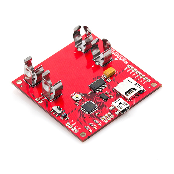
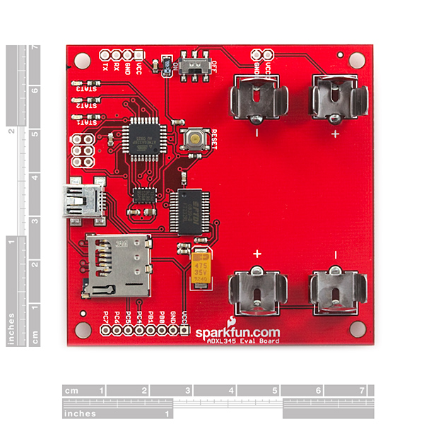
This is an evaluation board for the ADXL345 three-axis accelerometer. The ADXL345 is an awesome little accelerometer, capable of measuring acceleration of up to ±16g at up to 13-bit resolution. The evaluation board includes everything you'll need to adjust the ADXL345's settings, and monitor and log its outputs.
The on-board ATmega328 takes care of all the I2C/SPI communication with the ADXL345, and it will also log the x-, y-, and z-axis acceleration values onto a uSD card.
The board includes a USB interface, which allows you to read/write any of the ADXL345's registers using a terminal emulator. The default baud rate is 57600bps (8-N-1). The UART pins are also broken out allowing a direct TTL interface with the processor.
Power can be supplied by 2xAA batteries, or with a 3.0-3.3VDC power supply at the VCC/GND pins.
The ADXL345 evaluation board does not include batteries, uSD card or a USB cable, check the related items section below for these products.
- ADXL345 triple-axis accelerometer installed
- microSD card socket for FAT32/16 data logging
- ATmega328
- USB connector for serial communication
- 2xAA battery sockets to power board
- Pre-installed firmware logs ADXL345 outputs and allows you to read/write registers via USB
- 2.75x2.70"
Comments
Looking for answers to technical questions?
We welcome your comments and suggestions below. However, if you are looking for solutions to technical questions please see our Technical Assistance page.
Customer Reviews
No reviews yet.
Has anyone managed to program this board as an Adrduino via the USB?
I've posted about the problems I'm having here:
http://forum.sparkfun.com/viewtopic.php?f=7&t=20737
If anyone knows what I'm doing wrong - please let me know!
I have never used an arduino before, but nothing that I do seems to let me upload a sketch to this board. The fact that the schematic here is obviously incorrect does not help the situation. I have tried 2 different pc's, pressed reset, powered on, powered off, checked settings, etc...
Do I have to add connectors to the board?
If someone can help me out here it would be appreciated.
If I can't change the code, then I also need a hint as to the best way to convert the output into something more useful.
Hi Guys,
I need to capture a bandwidth of 500Hz, so need to sample at 1Khz.
Is it possible to reprogram the board to be able to sample and log data at 1KHz?
Thanks
There is no crystal visible on the schematic or the board. Does the serial work or is there some special calibration you are using?
The schematic says mega168, not mega328.
Note that the 328 should be drop-in compatible with the 168 so the difference shouldn't be an issue.
Looks like a neat set-up for some of us novices.
My problem: I have an existing project using an ADXL330 and ATmega168 that makes realtime calculations and controls the rest of the system based upon the current state of motion.
1) I'd like to move to to a higher resolution accelerometer/microprocessor in the +-1.5g range.
2) I'd also like to continue making fast(er) realtime calculations for feedback with the rest of the system.
3) I'd like to simultaneously record xyz accelerations (and maybe a few other sensor readings) to an SD card.
I'm not sure exactly what I'll need to do this or which accelerometer/microprocesser(s) I should choose. My layperson strategy would be to do the calculations/triggering and SD card recording using different microprocessors.
Any ideas or thoughts?
Analog has a new ADXL312 (automotive) with slightly higher resolution.
Depending on the rate, you should be able to record to an SD card. 2k-5k bytes per second to a fat32 filesystem.
Hi,
I want to change the firmware to configure the Accelerometer in 8 G or 16 G range at power up because I want to trial the sensor in a non-accessible location.
I have modified the command to do this in the adxl_defaults() routine and recompiled the firmware using the WinAVR toolset.
But I am not familiar with the Atmel processors or their programming tools.
How were the evaluation board processors originally programmed via the USB ?
What avrdude command or toolset can I use to reprogram with my new hex files? From reading the avrdude documentation it appears that the USB can be used but I do not know what programmer device to invoke.
Any advice will be much appreciated.
After some effort, I have a TWI version (http://harleyhacking.blogspot.com/2009/10/adxl345-at-full-speed-32khz-on-arduino.html) running at 3.2khz.
I was wondering what speed this can run at (to serial or logging)?
Te clarify, this is for a plain 3.3v arduino, not this board. But it does TWI.
I'll have to see if I can merge the FAT code...
Hi, are there some possibilities that in the next versions, ( if there will be more versions ) the battery holders will be removed? Using just a LiPo at 3.3V , the board sould be used as a personal motion data logger...very interesting!
I noticed that you are apparently bit-banging to emulate a second SPI instead of using the TWI interface on the Arduino (or you could have done SPI on the TWI pins to leave the option open). Is there a specific reason you did it that way?
Batteries plus an FTDI seem almost contradictory. The FTDI BoBs are small and inexpensive, and I think bluetooth (or Wifi) would be far more interesting to have on or available off battery power. My motorcycle project is a close variant - I was thinking of adding the logging to an SDHC and started the code gathering.
A board with the 345XL, the Venus GPS (with a 64Mb logging spi flash) with Arduino would be really nice (I would suggest bluetooth, but you use huge modules) would do more, but that would probably be pushing it.
What would be really useful is an "accelerino pro mini" - using the TWI pins and maybe the other pins if you prefer bit-banging maybe slightly stretched to acommidate the ADXL345. The TWI pins on the existing 3.3v pro-mini are already inside where they are hard to attach. You might need a smaller reset button but I think it would all fit.
Ok, I'm going to try to respond to everything, but some things may be missed:
We do bit-bang a second SPI to communicate with the sensor. The reason it doesn't share the bus with the SD card is that when you are writing to a FAT file, the communication must be un-interrupted. And the file write can take a long time. In order to maximize the bandwidth for the sensor communication we had to be able to talk to it while simulataneously writing to a file. So, using a second bit-banged SPI bus allows the use of SPI hardware to write files behind the scenes while talking to the sensor. Granted, I didn't implement this, but the design allows for it.
You're right that we could have used the TWI; but I hate I2C. So I didn't!
Now your next question: "Batteries plus FTDI seem almost contradictory." I don't really understand. We didn't want to provide power from USB because we wanted the board to be portable. FTDI was included on the board so that the board can be reprogrammed with the Arduino IDE, not necessarily for serial communication even though it did provide that extra benefit.
As for the rest of your comment, you might want to check out the KinetaMap. It's got an accelerometer, GPS and datalogging with a bluetooth module. You can hack the firmware to work with a faster GPS module if that's desired too.
To clarify, the FTDI needs 5v USB power to be useful, and is much slower than swapping the uSD card (into an ordinary reader). If enclosed with batteries, I would assume you could/would use the uSD to transfer and an ISP to reprogram it. If it has a USB connection, that is the easiest place to feed in power.
Good, bad, ugly...
The batteries take up half the circuit board and prevent it from fitting into a more cylindrical shape. Half size with screw holes to attach a 2 cell battery holder on the rear would have been better. Or something like the Lilypad booster but 3.3v. It is also low power unless something is really wrong with the design, so a coin cell would likely work very well ($3 CR2032s for $1 at dollar tree - or 2 fake candles with CR2032s and a LED with a flicker chip). Or for long term (I have 16Gb uSDHCs) a set of D batteries. Rechargeable with some of the recently restocked solar cells?
Let me put it simply. Except for a very narrowly targeted product (Wii?) DO NOT PUT BATTERY HOLDERS ON THE BOARD. I suppose you might fit a tiny coin cell without foreclosing other types, but there is no way of balancing the kind of power supply v.s. application. You will always choose the wrong battery size for over half the potential applications (other than something which is specifically a battery booster or something).
I can't even easily put any of your LiPo cells and you have all kinds of variants for that.
Hi,
You've got a good point, and I agree with the 'no battery holders' for the most part. We included the battery holders in part because this project was a collaboration project and our partner included this in the design specifications. It is unfortunate that it makes the package much bigger though.
My only counter point is that there is a power header on the board which allows you to power the board from any source you'd like (while using a coin cell would be admittedly difficult). For example, while developing code for the board I soldered on a two pin male header and then plugged in a LiPo battery pack. It was pretty simple even though it wasn't very pretty. You could also clip off the JST header of a battery pack and solder the wires into the power header on the board for a more secure connection.
I just measured the zip ties I'm currently using. A hole 4mm in diameter would work. Going to 5mm if there's room would help make a wider variety of zip ties work.
Yes, that'd do it. A small zip tie works just fine (usually we have to put a couple together end-to-end, but that doesn't change the size of hole needed).
A hole on either side would be best, though we could just wrap it around the outside edge of the board if there's no room on that side for a zip tie.
In general holes like that would be a good idea for boards that have battery mounts and high-g accelerometers. I think this board may be the only one you currently have like that, though.
A suggestion: a device like this is ALMOST ready to fly in a rocket. However, the battery holders alone are not going to be enough to hold the batteries in place under high accelerations (most importantly of the ejection charges). Normally we put a zip tie around them to hold them in place. With this board, that would probably mean drilling a hole in the board near that FTDI chip. If the board could be designed with that hole pre-drilled, high acceleration users wouldn't have to nervously put holes into a $45 board. I imagine it would cost almost nothing to do so.
Hello! Anytime one of our products can be used in a rocket we love to hear about it! I'm a bit concerned, though, about your aspirations to use this particular board in a rocket. It's a pretty big board, as far as our boards are concerned, so I'm assuming you've got a big rocket (which is good, of course). The problem is that this accelerometer will only measure up to 16 Gs. So, first off I don't think that the accelerometer would be able to measure the accelerations you're looking at. But, if it can, I don't think that 16 G's would knock the batteries out of the clips either.
Now, if you don't care about those two points then I thought I should offer some more productive suggestions:
1.) There are four mounting holes in the corners of the boards. You could probably get creative with a zip tie and secure the batteries by utilizing those holes.
2.) Duct Tape. You're not a 'real' hacker until you use it...thoroughly.
3.) You don't have to power the board using AA batteries if it doesn't suit your application. There is a power header next to the battery clips that can be used with alternative batteries (i.e. use one of our LiPo packs and double sticky tape it to the back of the board).
Good luck with your rocket. And send us pics/videos if you got 'em. (or better yet, post them on our facebook profile if you can).
I got this Evaluation Board - ADXL345,sku: SEN-09364 and would like to reprogram the board using arduino IDE as it says in the users guide. I am using a windows vista system and am not sure how to go about it. it would be great if you could help me out here a bit.
It's under 3" on a side, so it'd fit in plenty of rockets. 16G is sort of on the "light" side, but plenty of large high power rockets pull less than that. My first accelerometer project was a 5.5" diameter rocket that only pulled 10G.
When the ejection charges go off, though, you peak out way above that, and that'll knock the batteries out, probably. Since the mounting holes would be used for mounting, I'd still be inclined to drill a zip tie hole in the board.
I'm probably not going to use this board anyway, though, as I'm using a couple of SMT accelerometers these days, in your SOIC-20/protoDIP boards. But I just thought that in general if adding a zip tie hole were easy enough, you should consider it.
Sounds like a great idea! thanks! How big are your zip ties? Would a couple standard standoff holes do the trick?