- Home
- Product Categories
- Sensors
- Gyro Breakout Board - LPY530AL Dual 300°/s

Gyro Breakout Board - LPY530AL Dual 300°/s
Replacement:SEN-10099. The new revision corrects issues with the high pass filter. This page is for reference only.
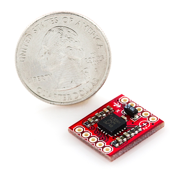
This is a breakout board for the ST's dual-axis LPY530AL gyro (don't mind the photos). The LPY530AL measures angular velocity along the pitch and yaw axes with a full scale of ±300°/s. Two different analog outputs are provided for both the x- and z- axes - one 1x amplified and the other 4x amplified.
A regulated voltage between 2.7 and 3.6VDC should be supplied to the power pins. We have the filtering circuits all set up; you'll just need to connect the outputs to an ADC, and you're ready to go.
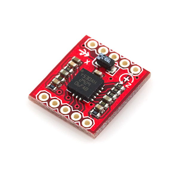
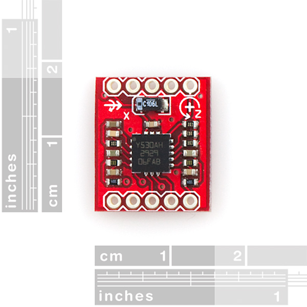
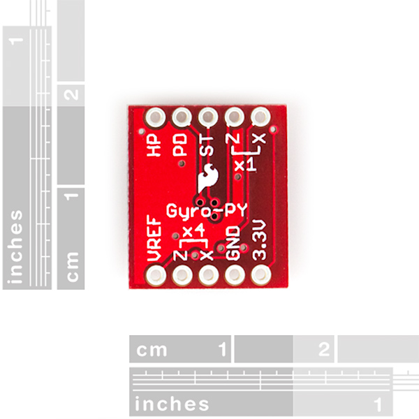
This breakout board includes the gyro and all necessary filtering capacitors as shown. The 1x and 4x amplified outputs of both axes are connected to the 0.1" pitch headers, along with the power-down, self-test, high-pass filter reset, and power pins.
Not sure which gyro is right for you? Our Accelerometer and Gyro Buying Guide might help!
**Note: **Some users have found that the high pass filter on this breakout board causes the output to be incapable of being integrated. A revision is coming that will have R5 and R8 removed and replacing C1 and C2 with a jumper.
- 2.7 to 3.6VDC power supply
- Dual axis, pitch and yaw sensing
- 1x and 4x amplified outputs for each axis
- Low power consumption
- All necessary filtering components included
- Access to power-down, self-test, and high-pass filter reset pins
- 0.6x0.7"
Comments
Looking for answers to technical questions?
We welcome your comments and suggestions below. However, if you are looking for solutions to technical questions please see our Technical Assistance page.
Customer Reviews
No reviews yet.
So, Will Sparkfun technicians correct the HP filter that this breakout board has?. Many of us need to integrate the output signal to get rotational position, but with this HP we'll obtain an error because of HP filter.in my opinion It would be the best to everyone to remove this HP filte
I have had the same issue with the high-pass filter on this breakout board and resolved it by soldering a jumper over C1 and C2 and removing R5 and R8, as suggested.
Here is what my data looked like with the HP filter:
Yaw Test WITH HP Filter
This is from an R/C truck driven in a tight 360 degree circle then stopping. The yaw rate output initially captures the 150 deg/s rotation, but the magnitude decreases even as the vehicle continues to rotate at a nominally-fixed rate. Once the vehicle stops, the output increases by 150 deg/s sharply, then decays gradually to zero at the time constant of the high-pass filter.
Conversely, this is data from a test of the gyro with the filter components removed:
Yaw Test WITHOUT HP Filter
The yaw rate output captures the nominally-constant rotation rate on the office chair and correctly shows zero rate after my shoes have finished scrubbing on the carpet.
The traces seemed abnormally sensitive and I ended up lifting two pads and a trace. This is my first time doing so, despite quite a bit of re-work on various boards. I ripped off the trace from the yaw gyro output completely and soldered a jumper directly from the ST gyro pad to the far pad on C2.
hello all..
Iam using LPY5150AL Breakout gyro. I have connected to a PIC16F877A microcontroller.The problem is that iam getting outputs of gyro around 1100 -1300 deg/sec when i rotate the axes.I donot know whether these values are correct are not??can anyone help me out..!
The formula used is:
X_deg=((V_out-V_reference)*5000/1024)/(sensitivity)
where v_ref=1.23 as suggested in datasheet.
THANKS ALOT..!
About the revision (will have R5 and R8 removed and replacing C1 and C2 with a jumper), it's done?
Previously I reported a DOA X-axis. After closer inspection, I see the chip is marked Y530AH -- I think I'm just holding the Z-axis-only version of the chip. I think that'd be an easy packing mistake, as they use the same board.
The strange behavior from the one "working" channel isn't answered yet, but I'll get in touch with SparkFun tech support.
For the benefit of those considering a purchase:
I've been in touch with SparkFun and confirmed that I actually have the 1-axis chip due to an error on my part. So, shop with confidence.
However, understand the schematic. SparkFun has included high pass filters on the break out board which may make the output not quite what you expect.
A common request from a gyro is for it to tell you its rate of rotation. By integrating that rate over time you'll be able to estimate changes in pose. Unfortunately the high-pass filter eliminates information about slow-changing rates. If you rotate the chip at a constant speed the output will initially register a rotation but eventually will slide back to reporting 0-rate, even though you're still spinning.
The parts are tiny, but if you can flick off one of the resistors and bridge across a capacitor, you'll disable the high pass filter. I did that, and I can now get usable data. If you want to try it, check the SparkFun schematic to identify the right parts to remove.
hello all.. Iam using LPY5150AL Breakout gyro. I have connected to a PIC16F877A microcontroller.The problem is that iam getting outputs of gyro around 1100 -1300 deg/sec when i rotate the axes.I donot know whether these values are correct are not??can anyone help me out..! The formula used is: Xdeg=((Vout-Vreference)*5000/1024)/(sensitivity) where vref=1.23 as suggested in datasheet. THANKS ALOT..!
The X-axis on mine (both 1x and 4x) was clearly dead on arrival. No response to motion at all.
I had some hope for the Z-axis, which was the only one I cared about. When bouncing it around in my hand, it seemed responsive in about the right way. Now that I've gotten around to testing on a spinning table, it doesn't seem to respond correctly at all. If you let it spin down to a stop, the output will overshoot and takes more than a full second to recover to the zero-value. Weird.
SparkFun:
A suggestion. Your engineers are making some design decisions when they choose what pins to break out and what discrete components to add to the break out board. A quick application note for how they intended the breakout board to be used would be very helpful. For a board like this, that would be really easy for you to do and would answer the majority of the questions that pop up in the thread.
Sorry you're having problems with your board, contact us at techsupport at sparkfun and we'll talk about testing and replacing your unit.
And thanks for your other comment. We feel your pain re. documentation or lack thereof. The primary purpose of most of our boards is to provide access to cool parts that are otherwise hard to impossible to connect to electrically. For our "widget" boards, where we've come up with new functionality, we do our best to document how to use them. But most of our breakout boards are based on reference designs provided by the chip manufacturers in their datasheets and application notes. The manufacturer's datasheet should always be the final word on how to interface to these parts.
How can Vref be made use of while providing a driver interface for this particular gyro sensor?
Is there a need for calibration of any sort?
Has anyone sorted this one out yet? I just got mine out of the box and started testing but with little luck.
I�ve only connected 4pins: GND and VCC (3.3v regulated with a LP2950 voltage regulator) , and X/Zx4. The other pins are "fluctuating".
X/Zx4 connected to 2 ADC ports on a PIC16F877A and i only get readings around 384 and it doesn�t seem to change much as i mess around with the gyro.
X/Zx1 stays "zeroed".
Any thoughts?
Hey Kindof,
If you read this, could you let me know what exactly you did to get good data off of this gyro. I am using an arduino pro mini
I have hooked Vdd/Vref to an external power supply (not through the arduino), HP/PD/ST/Gnd to Ground. It does not matter if I read values off of 1x or 4x, the adc value just sits at 638 with no real change. Any thoughts?
Update.
This gyro is working great, I have it running in a kalman filter with a digital accelerometer. No problems with it, very responsive, and quite accurate.
Cheers
Hey Kindof,
If you read this, could you let me know what exactly you did to get good data off of this gyro. I am using an arduino pro mini
I have hooked Vdd/Vref to an external power supply (not through the arduino), HP/PD/ST/Gnd to Ground. It does not matter if I read values off of 1x or 4x, the adc value just sits at 638 with no real change. Any thoughts?
Hello,
I have gotten some readings out of this and it seems to be a pretty decent gyro. I have 3.3v to the ard's 3.3v, same with VREF (I am not certain if this is a best practice yet), then I grounded PD/ST also ground to ground.
I then hooked the Z/X to ADC's on the Arduino. The readings seem to sit around 680. Which is roughly .664 of 5v's.. AKA 3.3v's. Which is about right for the VREF I am giving it.
When twisting it and messing around the gyro's I can get the reading to bounce between 640 and 740 or so. I have not tried the 4x yet, but according to the data sheet you'll need to short the 1x's to each other before 4x will output.
I have output its readings in line with an accelerometer and it matches up... so I think its functional.
Hope this helps everyone out..
Hi I have purchased one of these units but am unable to get any reading from the output, have you got some sample Arduino code and wiring diagram I can used. Currently wired up 3.3. v and grnd and connected X1 Z and X to Analogue pins tried code from http://voidbot.net/razor-6dof.html but no Joy
Has anyone got one of these up and running yet? General comments? Drift?