- Home
- Product Categories
- Development Tools
- GPS Shield

GPS Shield
**Replacement: **GPS-09817. We added the ability to select which digital pins connect to the Arduino board. This page is for reference only.
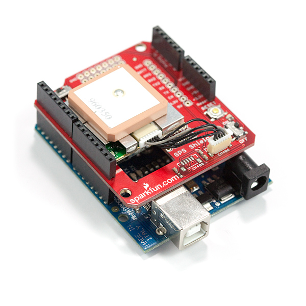
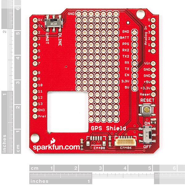
With the GPS Shield you can add GPS functionality to your Arduino. A connector for the popular EM-406 GPS receiver is populated on the board, and footprints for EM-408 and EB-85A connectors are also made available (connectors are not soldered on or included and can be found below in the related items). The regular GPS pins (RX, TX, PPS, etc.) are also broken out to a 10-pin 0.1" pitch header, and a small protoyping area is also provided.
The DLINE/UART switch switches the GPS module's input/output between Arduino's standard TX/RX pins and digital pins 2 and 3.
DLINE must be selected in order to upload code through the Arduino IDE.
An ON/OFF switch is included which controls power to the GPS module. Finally, the Arduino reset switch is also brought out.
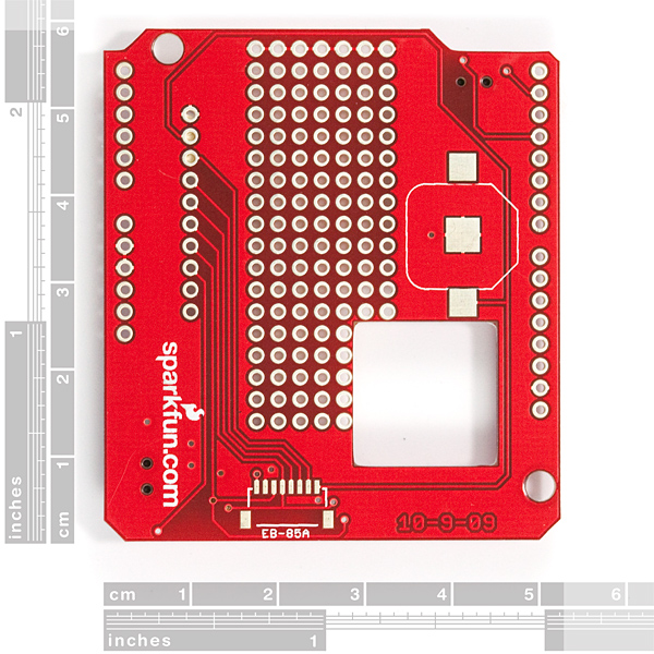
The shield also includes the footprint for a 12mm coin cell battery holder to provide battery backup to the optional EB-85A gps module.
**Note: **GPS modules are not included with the GPS Shield, and only the EM-406 connector is populated. Headers are also not installed, we recommend the 6 and 8-pin stackable headers.
- EM-406 connector populated and connected to Arduino UART pins (D0/D1)
- EM-408 and EB-85A connector footprints provided and connected for optional use
- Coin cell battery socket footprint provided and connected for optional battery backup of EB-85A GPS module
- Standard Arduino sized shield
- Prototyping area
- GPS serial and PPS signals broken out to a 0.1" header
- Arduino reset button
- ON/OFF switch controls power to GPS module
GPS Shield Product Help and Resources
GPS Shield Hookup Guide
March 9, 2015
This tutorial shows how to get started with the SparkFun GPS Shield and read and parse NMEA data with a common GPS receiver.
Comments
Looking for answers to technical questions?
We welcome your comments and suggestions below. However, if you are looking for solutions to technical questions please see our Technical Assistance page.
Customer Reviews
No reviews yet.
I was just able to get my shield running on a Duemilanove. I copied code from www.ladyada.net.
It didn't work. I had to switch the numbers (2,3) to (3,2) in the call to NewSoftSerial.
This is the top of the code from ladyada. It has my change in it.
// A simple sketch to read GPS data and parse the $GPRMC string
// see http://www.ladyada.net/make/gpsshield for more info
include
NewSoftSerial mySerial = NewSoftSerial(3, 2); // this was reversed in the example. I fixed it by luck
define powerpin 4
define GPSRATE 4800
//#define GPSRATE 38400
Interesting. I just had the same issue with the example that comes with the TinyGPS library that Mikal wrote (yea, pretty sure he's seen an Arduino or two :) I'm using the EM406a gps.
Why does this happen? Does the shield reverse the RX and TX pins somehow? Just to clarify, I was using the sketch 'Test_with_GPS_Device'
With the unmodified sketch, the serial monitor would output:
"Testing TinyGPS library v. 9
by Mikal Hart
Sizeof(gpsobject) = 103"
Once I changed the line:
NewSoftSerial nss(2, 3);
to
NewSoftSerial nss(3, 2);
I got the correct output with all the coordinates
Thanks for that tip..works a charm :D
Very nice, been longing for something like this. Any issues with piggybacking this with the new "microSD Shield" you just released? I'm looking for a GPS data logger and that combo may just be the answer.
Im not sure but it looks like it can, also...adafruit offers one with data logging built in with a microsd on the back.
It worked great for a GPS tracker integrated with Google Maps that I built. For details, please visit
http://jayeshprojects.blogspot.com/2010/04/real-time-mobile-gps-tracker-with.html
I've just hooked one of these up with software power control - just solder a header on to the breakout, hooking the 5v and 3.3v lines to the emitters on a couple of transistors, then just hook the bases together, hold them low and attach them to your favourite free I/O pin, attaching each transistor's collector to 5v and 3.3v respectively.
Voila! Software power control - works a treat, if a little messy (but hey, that's what the prototype shield is for!)
Incidentally, as it is connected to an I/O pin, when you program the Arduino, the GPS is automatically turned off as the pins go floating and I'm pulling the gates low :D
See: http://farm4.static.flickr.com/3656/4554430700_4455a1b4c4_b.jpg
I added a 6 pin header in the prototyping area with the end pin on the ground bus. You can plug a USB-TTL serial cable (as used with Boarduino, Pro etc) onto this. Patching the 4th pin along (orange on my cable - TX Data) to the TX pin connects the two outputs together.
Then you can either (i) switch the GPS power on and get real data or (ii) switch the GPS power off, connect a cable and test indoors with any program that can send NMEA sentences to a COM port at 4800bps. I used MS Flight Sim with the GPSout plug-in but there are many apps that will do this.
Is the SirF's default output NMEA or binary? Is that selectable?
Is there a way to tell the GPS module (if SirF) what NMEA sentences to generate? (for ex GPGGA only, to cut down on processor load).
If I use an EM-408 wouldn't the rx/tx voltages not work?
Is there anyway to add a switch to this to switch the rx, tx pins on the DLine so rx is on pin 3 and tx is on pin 2
so cant it be used for 50 Channel GS407 Helical GPS Receiver ???
How does the GPS unit mount to the board? Is it just glued?
Do you even have an arduino?
I think the poster was asking how the module attaches to the shield which is a legitimate question. If the module is glued or double sided tape is used, it would be very difficult to remove the GPS module.
Looks good the only thing that could be improved on is adding a transistor to turn it off to save power when reading intermittently.