- Home
- SparkFun XMega100 Breakout

SparkFun XMega100 Breakout
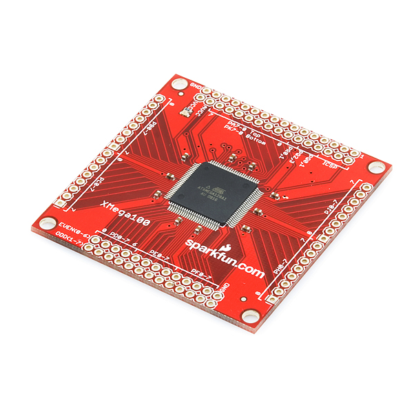
This is a breakout board for the 100-pin TQFP package of Atmel's ATxmega128A1. The ATxmega128A1 is a low power, high performance and peripheral rich CMOS 8/16-bit microcontroller based on the AVR enhanced RISC architecture.
Among the chip's many features are 128kB of flash memory, 8 kB SRAM, 78 I/O pins, eight 16-bit timers, sixteen 12-bit ADCs, four 12-bit DACs, eight USART, four SPI and four TWI interfaces. This powerful chip can process up to 32 MIPS when running at its maximum clock speed of 32MHz. The operating voltage of the xmega is 1.6 to 3.6VDC.
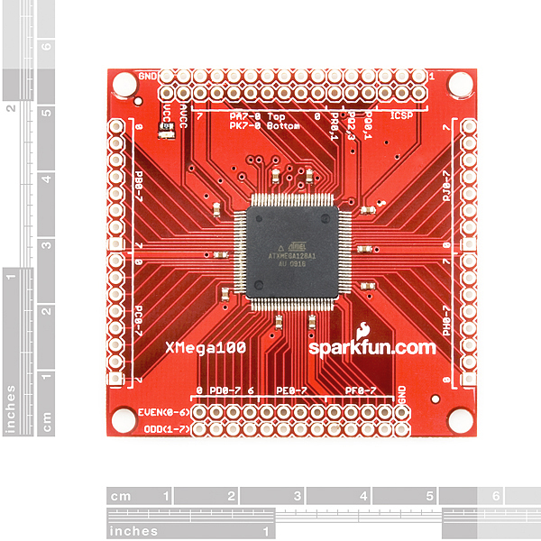
All VCC pins of the ATxmega128A1 are connected together and brought out to a single header pin, same goes for the GND and AVCC pins of the chip. We've also included decoupling capacitors, and a red power indicator LED; but beyond those we've tried to keep the board as simple and straightforward as possible. If you want to start developing with this chip, but don't want to deal with soldering it, this is the board for you!
**Note: **The 6 pins labeled ICSP are used to program the board through the PDI interface using the common 6 pin ICSP cable found on most AVR programmers. Also, this board ships with the example code shown below and the JTAGEN bit set to 1 (JTAG disabled, PDI enabled).
Note: We have found that when using a Dragon device, you must use the JTAG interface, you can not program/debug over PDI. If you are using the JTAGICE3 you can use either JTAG or PDI however, you will need to change the PDI clock to run at 1 MHz or slower.
- All pins of the ATxmega128A1 broken out to 0.1" spaced pins
- 0.1uF decoupling capacitors placed near VCC inputs of the chip
- 2x3 AVR ICSP connector broken out
- Red power indicator LED
- ATxmega128A1 Features:
- High-performance, low-power 8/16-bit microcontroller
- 1.6 - 3.6 VDC operating voltage
- 128 KBytes Flash
- 8 KBytes boot code
- 2 KBytes EEPROM
- 8 KBytes SRAM
- 4 DMA channels
- 32 MHz maximum clock frequency
- 78 programmable I/O pins
- Eight 16-bit timers
- Eight USARTs, four SPI, and four TWI interfaces
- Two Eight-channel (16), 12-bit, 2 Msps Analog to Digital Converters
- Two Two-channel (8), 12-bit, 1 Msps Digital to Analog Converters* 2.20 x 2.20" (55.88 x 55.88mm)
SparkFun XMega100 Breakout Product Help and Resources
Core Skill: Soldering
This skill defines how difficult the soldering is on a particular product. It might be a couple simple solder joints, or require special reflow tools.
Skill Level: Rookie - The number of pins increases, and you will have to determine polarity of components and some of the components might be a bit trickier or close together. You might need solder wick or flux.
See all skill levels
Core Skill: Programming
If a board needs code or communicates somehow, you're going to need to know how to program or interface with it. The programming skill is all about communication and code.
Skill Level: Competent - The toolchain for programming is a bit more complex and will examples may not be explicitly provided for you. You will be required to have a fundamental knowledge of programming and be required to provide your own code. You may need to modify existing libraries or code to work with your specific hardware. Sensor and hardware interfaces will be SPI or I2C.
See all skill levels
Core Skill: Electrical Prototyping
If it requires power, you need to know how much, what all the pins do, and how to hook it up. You may need to reference datasheets, schematics, and know the ins and outs of electronics.
Skill Level: Rookie - You may be required to know a bit more about the component, such as orientation, or how to hook it up, in addition to power requirements. You will need to understand polarized components.
See all skill levels
Comments
Looking for answers to technical questions?
We welcome your comments and suggestions below. However, if you are looking for solutions to technical questions please see our Technical Assistance page.
Customer Reviews
4 out of 5
Based on 1 ratings:
1 of 1 found this helpful:
Not bad!
This is the I/O land of milk and honey. No shortage of serial ports or I/O pins! I do have two suggestions: Add a 16MHz crystal, or even just the mounting holes for one (even though it will run out-of-the-box with the 2MHz RC oscillator built in). Also, bring the programming port out with enough room around it to put in a shrouded connector. You have to leave 4 pins next to the programming port empty in order for the mkII ISP connector to fit. The pins next to the ISP port are for crystals.
For the record I would love to see an updated/alternative version of this based on the ATxmega384C3, 32K of SRAM, 384K of Flash, 4K EEPROM, built in USB, etc.
Yes, other xmega chips would be both useful and desirable. As an example, I used a 44 TQFP breakout with an ATxmega64D4 to prototype a design that replaces an ATmega328 with the xmega [the 44-pin TQFP breakout was both awesome and inexpensive, but I had to order the CPUs separately from someone else]. A minor tweek to that might have the ATxmega64D4 (or similar) pre-soldered onto the board to make this easier and more convenient. Even better, pre-wire up the Vcc and GND connections with bypass caps so I don't have to use 'blue wires of salvation' to wire them up, and then have to solder on the capacitors by hand. OK I guess that makes it a 'different board' but still... it's a want.
I've got the definitive word from Atmel about using the Dragon with this chip.
The Dragon can communicate using ICSP or PDI. It uses the same cable on the same connector with the same pinout for either.
The Dragon will not program ATXMegaA1 devices using the PDI mode interface. There was some confusion about this point both here, on the net, and in the AVRStudio documentation.
I've personally verified this: the Dragon can't do it.
The most recent version of AVRStudio has the correct documentation, previous versions imply (incorrectly) that you can program these devices.
Since the chips in this product have JTAG turned off by fuse, it is thus impossible to use this product with a Dragon.
The Dragon will program other ATXMega devices using PDI, just not this one.
According to a direct answer from Atmel, the AvrISP MkII is able to program these chips using PDI.
I want to order one of these microcontrollers... but could SparkFun change the JTAGEN bit at the time of shipping so that JTAG is enabled? I don't have a JTAGicemk2 and have always used my Arduino to program AVRs.
Why is PDI even enabled in the first place? Is there an advantage over JTAG?
Using LUFA and the XplainBridge and AVRISP mkII clone, you can convert the Xplain board to be recognized as an AVRISP mkII programmer from AVRStudio and program the XMEGA chip on the Xplain board, without the need of any extra PDI programmer.
The AVRISP mkII can also program over the PDI interface. It's very very easy to wire a 6-pin icsp connector as a PDI programming port.
It's about time sparkfun got ahold of the Xmegas. They're powerful little chips
If you want something with some more components, I recommend looking at Atmel's 'Xplain' board. It contains the same IC as this breakout board, but for only $4 more you get 8MB of SDRAM, 8MB serial Data Flash, a secondary AT90USB chip which can be used for USB communication, a temperature sensor, a potentiometer, 8 push bottuns, 8 LEDs, and a small speaker
The XPlain boards are good for demos, but they don't break out all the pins, so you just get port D - 2 timers, 2 uarts, etc. and some of the other stuff is dedicated.
Regarding the review on this item from "avrguy":
For anyone who requires the ability to add a crystal for the Xmega, please refer to this item: http://shop.in-circuit.de/product_info.php?products_id=176
It seems to be similar to the Sparkfun Xmega100, but with pads for an external crystal.
For anyone that may be interested, I developed a real time operating system, hardware abstraction layer, and fixed-point math library that works with this part. Here is a link to the source code and project description https://code.google.com/p/arbitros/.
Thanks for sharing!
I just purchased this board and, after some research, I still have a question about the PDI interface. I see Atmel uses an AT90USB chip to transmit data to the XMega. I don't have an AT90USB, but I do have the (older) Sparkfun ATMega8u2 break-out. Is it possible to use the 8u2 to program the XMega over PDI?
I'm new to Eagle. On the www i found a XMega100_BOB-v11.sch and .brd of this BOB, but there doesn't seem to be a library. I tried just to insert this .sch file to my own schema: "The light edition of EAGLE can't perform the requested action! There not enough sheets.' Is there a way around? Is there a library around including this BOB? or other way to convert the schema to a lbr? I tried exp-project-lbr.ulp but htat only exports the xmega processor, which is already in the sparkfun lbr
Do you plan on selling the chips by themselves?
Do you plan on selling the chips by themselves?
According to the Parameters page for this chip on the Atmel site, there are 12 SPI. Why are there only 4 SPI on this proto board?
It is a typo on the homepage, it only has 4 SPI.
On a related note to this card, xmegaduino beta 1 is released at https://github.com/akafugu/Xmegaduino/downloads Testers needed.
I need to know that
Is bootloaded section of this controller is functional or not? (B/c in earlier versions of this controller, Bootloader was not functional, support for bootloader is functional in newer release, so kindly tell me the the version of this controller like: ATxmega128A1 rev. H)
ATxmega128A1 is preloaded with Bootloader Program or not?
I've asked Atmel about this topic and here is the answer I've got:
Dear Customer,
Thank you for contacting Atmel Technical Support.
Support of XMega PDI interface in Dragon basically depends on the revision of the XMega devices. So probably you don’t have to care about hardware revision of Dragon Programmer.
PDI mode on Dragon only works for the parts as mentioned below:
XMega - A4/D4 -> Rev A onwards (It means all will support)
XMega - B1 -> Rev A onwards (It means all will support)
XMega - A1 -> Rev J onwards (But Rev J is not yet in production)
XMega - A3/D3 -> Rev D and rev F onwards (But not yet in production)
You may please refer help section from Studio4 to get the device support details.
(Studio 4 --> Help --> AVR Tools User Guide --> AVR Dragon User Guide --> Introduction --> Device Support)
As I mentioned above current revision of Xmega128A1 does not support PDI interface in Dragon programmer.
But you will be able to use the JTAG interface of Xmega128A1 to connect with Dragon and to know more details on JTAG interface of Dragon you can refer help for this.
(AVR Dragon User Guide --> Connecting the AVR Dragon --> Debugging --> Connecting to target through the JTAG Interface)
Please do not hesitate to contact us again if there is anything else we can assist you with
Best Regards,
Shakkeer Muhammed
Atmel Technical Support Team
Hope it helps. The only option now is to wait for the Rev J so we can program with the Dragon.
Hello, is this breakout board also useable for the AT32UC3A1512?
Thank you
This board looks like it would be fun to use for an embedded device in a router WL-500g.
Plenty of I/O and other than maybe some voltage conversion for some devices, it would be excellent and fast.
The only thing I cannot figure out is how to program the thing. If it supported ICSP I could rig my Arduino to do it, I think. Does it need to be 3.3 or 5 to program it?
Edit: Actually, if it can do ICSP I can program it from an internal serial port on the router using AVRDude. I could also put all of my development tools on the router as well. I may even be able to put a console on a webpage on the router. Full programming from a web interface. The device could be on the other side of the globe... hmmm... I think I will do just that. Sweet!!!
just imagine an arduino with this chip...
Anyone had success programming this device?
I have Avr Dragon and have not been able to program.
AvrStudio 4.18 says it only supports JTAG. Some sites online says PDI mode, etc etc. Tried to hook up JTAG on PB7-5 + RST + GND + VCC but no success with that either.
It seems that the Dragon can program the Xmega128A1. But only the newer versions of the programmer. According to the Atmel Dragon's page the Xmega128A1 is listed as a supported device:
http://www.atmel.com/dyn/products/tools_devices.asp?category_id=163&family_id=607&subfamily_id=760&tool_id=3891
The new version of the board, according to the AvrFreaks forum, have the text "A08-0396.D" printed on the backside of the board and have mounting holes.
http://www.avrfreaks.net/index.php?name=PNphpBB2&file=viewtopic&t=88471
Can the xmega100 work with arduino bootloader without problems ?
And how Im going to solder that thing on the above break out board?
It seems to have so many pins that it will be hard to solder it .
I would assume that the xmega will work with the arduino bootloader, but it would take some minor editing to work properly, this breakout board comes preassembled but if you ever need to solder fine pitch SMD components sheck out the Sparkfun tutorials.
http://code.google.com/p/xmegaduino/
According to Atmel's site, the Xmega128A1 supports ISP programming. Could someone verify if the ISP fuse is enable ? I have a Dragon and don't want to buy another programmer just to use PDI.
Thanks
https://spreadsheets.google.com/ccc?key=0AoP0n2hdL3uvdEhLbW5Nbnplc1NaQzhnWVRzV0h5ZVE&hl=en&authkey=COqE0tIL<br />
<br />
Check that link out for a register comparison between this MCU and the other ones in the A family.
How many PWM does it have?
The datasheet seems to say that 1 timer = 1 PWM output, so eight.
Has anyone been able to program the xmega using avrdude with either an avrisp2 or a dragon?
When I try to do this with the avrisp2, I get the message:
avrdude: usbdev_open(): Found AVRISP mkII, serno: 0000B0041148
avrdude: usbdev_open(): error setting configuration 1:
usb_set_configuration(SetConfiguration): device not opened for exclusive access
avrdude: usbdev_open(): did not find any USB device "usb"
When I try to do this with a dragon:
avrdude: jtagmkII_recv(): Got message seqno 1 (command_sequence == 1)
avrdude: Recv: . [a0]
Raw message:
0xa0
FAILED
avrdude: jtagmkII_setparm(): bad response to set parameter command:
RSP_FAILED
I have an AVR Dragon, and one of these boards, but I can't find anywhere it says how to connect the two together for programming and/or debugging.
Progress, maybe.
First, the JTAGEN fuse is UNPROGRAMMED, so the upper 4 pins of port B (4-7 are TMS/TDI/TCK/TDO) won't act as JTAG until this is done.
The Dragon won't do PDI (but I had access to a JTAGICE), but will recognize and do JTAG if you enable this bit.
http://www.nongnu.org/avrdude/user-manual/avrdude_20.html
Has the JTAG to PDI adapter pinout, and it works on a JTAGICEmk2. I'll try the dragon later when I have a chance.
Any chance this board will be sold unstuffed? I already have a chip.
Contact SparkFun via email. they might be able to sell you one.
Check out this port of the Arduino IDE, bootloader, and runtime to the xmega: http://code.google.com/p/xmegaduino/
Right now the runtime and bootloader run only on the xplain. I'm now in the process of porting to the sfe xmega100 breakout. I may also give a crack at porting to the stack foundaries boards, and boston androids.
im confused, would something like the pocket avr programmer be able to program this via six-pin icsp, or do i need a special pdi programmer?
Rubi: Support of the Adurino Ide would be awesome
I agree, reworking the arduino mega boot loader and having the option to buy this BOB with it preinstalled would be a definite seller
Support of the Adurino Ide would be awesome
I guess an external oscillator is needed. There is one on this website (sku: COM-00540) not exactly 32Mhz, can they be used together?
ATxmega includes an internal 32.768kHz oscillator accurate to +/- 0.5%, and a 2 or 32MHz accurate to +/- 1.5%. This is suitable for serial communication.
You could add that external crystal if you want higher accuracy for something like timekeeping.
The Atmel AVR Dragon can be used for debugging and programming the Xmega via the PDI interface. They are $50, IIRC.
@Quazar: you are right... and all the programmers related to the board cannot program it, what makes me think that the person who designed this board has no clue about the XMEGA or they just didn't care to review the related products.
Why the ICSP connector? This chip doesn't support ISP programming, only JTAG and PDI.
If you look closely at the schematic, it appears the "ICSP" port is actually wired as a PDI port.
It would be nice if this were labeled correctly to avoid confusion, but at least the port is useful as-is.
Cheers,
- Dean