- Home
- Product Categories
- Sensors
- Triple Axis Accelerometer Breakout - MMA7361

Triple Axis Accelerometer Breakout - MMA7361
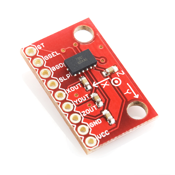
This is a breakout board for Freescale's MMA7361L three-axis analog MEMS accelerometer. The sensor requires a very low amount of power and has a g-select input which switches the accelerometer between ±1.5g and ±6g measurement ranges. Other features include a sleep mode, signal conditioning, a 1-pole low pass filter, temperature compensation, self test, and 0g-detect which detects linear freefall. Zero-g offset and sensitivity are factory set and require no external devices.
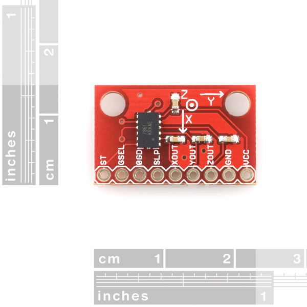
This breadboard friendly board breaks out every pin of the MMA7361L to a 9-pin, 0.1" pitch header. The sensor works on power between 2.2 and 3.6VDC (3.3V optimal), and typically consumes just 400µA of current. All three axes have their own analog output.
Not sure which accelerometer is right for you? Our Accelerometer and Gyro Buying Guide might help!
- Two selectable measuring ranges (±1.5g, ±6g)
- Breadboard friendly - 0.1" pitch header
- Low current consumption: 400 µA
- Sleep mode: 3 µA
- Low voltage operation: 2.2 V - 3.6 V
- High sensitivity (800 mV/g at 1.5g)
- Fast turn on time (0.5 ms enable response time)
- Self test for freefall detect diagnosis
- 0g-Detect for freefall protection
- Signal conditioning with low pass filter
- Robust design, high shocks survivability
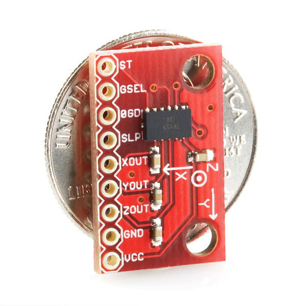
0.90 x 0.50"
Documents:
- Eagle Files
- MMA7361L Datasheet
Triple Axis Accelerometer Breakout - MMA7361 Product Help and Resources
Core Skill: Soldering
This skill defines how difficult the soldering is on a particular product. It might be a couple simple solder joints, or require special reflow tools.
Skill Level: Noob - Some basic soldering is required, but it is limited to a just a few pins, basic through-hole soldering, and couple (if any) polarized components. A basic soldering iron is all you should need.
See all skill levels
Core Skill: Programming
If a board needs code or communicates somehow, you're going to need to know how to program or interface with it. The programming skill is all about communication and code.
Skill Level: Competent - The toolchain for programming is a bit more complex and will examples may not be explicitly provided for you. You will be required to have a fundamental knowledge of programming and be required to provide your own code. You may need to modify existing libraries or code to work with your specific hardware. Sensor and hardware interfaces will be SPI or I2C.
See all skill levels
Core Skill: Electrical Prototyping
If it requires power, you need to know how much, what all the pins do, and how to hook it up. You may need to reference datasheets, schematics, and know the ins and outs of electronics.
Skill Level: Rookie - You may be required to know a bit more about the component, such as orientation, or how to hook it up, in addition to power requirements. You will need to understand polarized components.
See all skill levels
Comments
Looking for answers to technical questions?
We welcome your comments and suggestions below. However, if you are looking for solutions to technical questions please see our Technical Assistance page.
Customer Reviews
No reviews yet.
I am an electronic neewbie. My collegue connected the sensor MMA7361 to an Olimexino STM32, and wrote a code to record acceleration. I conducted a test "Zero". I recorded the three axis acceleration and calculated the module in a stationary condition. Instead reciving the expected 9,8m/s^2 result the value was 8,4 m/s^2.
Why this difference? Does this problem occur frequently? What is the reason?
Can i operate a linear trasformation on my three axis (ex if they are correctly alligned and the result is X=0 Y=0 Z=8,4m/s^2 can i add with a linear trasformation 1,4m/s^2 on my Z axis?
You're going to want to contact our Tech Support department on this as there is a multitude of situations that could be leading to you not getting a 1 G reading on the Z axis when it's stationary.
I've just bought one of these modules and I have put a pullup resistor to the sleep pin to high, supplied the sensor with 3.3V and only get a 0V readout on all the x, y and z. Does anyone have any idea what I could be doing wrong?
HEy, guys! This accelerometer doesn't support I2C right? It outputs analog right? Cause I don't want I2c at all, its too complicated.
You are correct.
Excuse my complete ignorance, but does this board come with an accelerometer already soldered in place or do I need to buy one separately and solder it on myself?
This board comes with the accelerometer already attached. The only soldering you should need to do with this would be either adding headers or jumper wires to the board.
I have a simple question, I got the MMA7361 accelerometer and I would like to know how to set it up as anolog, I don't quite understand if the schematic is for digital connectivity or analog and I require an analog, can anybody help me out?
both links are 404...
Is this directly compatible with the Arduino Tutorial here http://www.arduino.cc/en/Tutorial/ADXL3xx???
hi i have all the rest of my system that is under 5V is it possible to put a resistor or a diode between my 5V and my vcc-and high pins?
I know it could be a stupid question,but it's my first time on buying such components. This product include both the accelerometer and the board or only the board? Also,the board is necessary or can i use the "Triple-Axis Accelerometer - MMA7361L" directly?
Thanks.
Why do you use 2.2nF caps instead of the 3.3nF recommended in the datasheet? I have found 3.3nF to provide much less noise in the output than 2.2nF.
I can't download Datasheet because of damage.
plz replace it.
We have verified it a few times, it works. Check it on your end. Maybe your PDF reader or anti-virus is corrupting the file.
Does this board have a built in voltage regulator cause i'm afraid I might fry the board when I use HIGH to turn off the sleep
No, it does not. I would recommend getting a voltage regulator like this one: http://www.sparkfun.com/products/526 . Its what I'm using with the ADXL335, another accelerometer.
Does this board have a built in voltage regulator cause i'm afraid I might fry the board when I use HIGH to turn off the sleep
You have to drop the voltage to 3.3v. You won't fry it (you will eventually) you will just put a lot of electrical stress on it.
Sensor Interfacing
I just got a few of these, and connected as stated vdd=3.3 v, gnd=ground, and xyz are the outputs to a meter, common ground. I'm not getting anything but like .0002 on the meter, and I tried 2 of them and the same results, my power is from prt-00114 power supply, any advice?
thanks
What do you have the sleep pin doing? You'll need it pulled high for normal operation.
Confirmed, you do need an external pull up on the sleep pin but the g-select has an internal pull down for 1.5g operation.
External pul up?! Please explain! 10K or 1K?! Thank you
I am still learning about pins. I am using this board without an arduino or other microcontroller and want to just read the voltages coming out of the x/y/z pins with a meter. How can I pull the sleep pin to high without a board? My current understanding is to use a resistor and a ground connection, but want to confirm.
High means that you'll want a resistor and a power connection. I haven't looked into the specifics of this board, but from the sounds of it, you'll want sleep pin -- 10k resistor -- 3.3 volt power.
Anyone know where I can find validation measurement of this sensor? ( graph of digital readings vs. acceleration )
I thought the datasheet would contain info like this to show its accuracy/linearity, but it does not seem to be true.
Could you also provide the eagle Library part for this product ?
Link to schematic appears to be broken...
I've been looking for replacement for MMA7260 -- analog 3-axis with adjustable g settings. This looks pretty close, except that I can't use 4g.
Is this the closest we'll get to replace MMA7260 in a while? Or is there another Freescale sensor on the way?
They state in the buying guide that the MMA7260 has reached end of life, so well have to make do with this one.
Hi, The data sheet reccomemds 10M ohm resistors on the x,y,z outs. Is that pull-up, or pull down? And, in series with each of the 3.3nF caps? (The circuit dia doesn't show.)
a hint for an arduino library for these... https://code.google.com/p/mma7361-library/
I bought one of these awhile ago and i just have been testing it and i have a 10K resistor on the sleep pin and 3.3 volts going into it, and ground is connected but it still won't vary the voltage on the tilting, i need a tutorial that works with the arduino... PLEASE!!!!
a library you can use... https://code.google.com/p/mma7361-library/
how to use accelerometer to calculate and detect earthquake? help me please.. anyone who have code about this, share it for me..
We have an old tutorial on an earthquake logger here. That should be a good starting point for you.
is this model same with the following?http://www.dfrobot.com/index.php?route=product/product&product_id=507#.UmnXJWGwqAg
Is this appropriate for use in a segway? I'm trying to figure out if I need to buy something with a gyro too like here: https://www.sparkfun.com/products/11028
Browsing the Sparkfun website is like reading a good book, can't help but come back to it! :D
This sensor confused me, but I was able to figure it out.
First off it is automatically in sleep mode. To take it out of sleep mode you must run a 10k resistor from the sleep mode pin to the vcc. Also you do not need a logic level converter. Simply use the 3.3 on your Arduino for the vcc and just run the x/y/z into three separate analog ports.
EDIT: Never mind! I screwed up the conversion to voltage from the analog value.
I just recieved one of these sensors but I'm a bit confused by the output it gives me.
I'm using it with my Arduino and I'm providing it through the 3.3V output.
Though the 0G outputs differs quite a lot between the X Y and Z outputs. For X the 0G voltage is 1.15. For Y it's 1.25 and for Z it's around 1.6 volts.
Any ideas of what might be the cause?
The tolerance for the zero, and scaling of this chip is very loose. You will have to do what is called a 3-Point calibration. Take one reading at -1g's one reading at 0-g's and one reading at +1g's then use those three points to find the slope (scaling factor mV/g) and offset (0g point). y=mx+b
Since this is 3.3 volts does this mean to use with arduino u have to use logic level converter or can u just power it with the 3.3 v pin on the arduino?
Little late but you do not need a logic level converter!
Does this have the gyro chip in it? or is it only the board?
My accelerometer is showing 1.6v at 0 degree. The voltage goes up turning it one way, and goes downwards the other way. But on 180 degee it shows 1,6v again. Is this correct? How do I know if the accelerometer is 0 degree or 180 degree?
Just take a look at this: http://www.freescale.com/files/sensors/doc/app_note/AN3461.pdf
Sparkfun might consider adding opamp voltage followers, as the output impedance of the chip is very high, so the common use of input to the variable-impedance Arduino analog-in will cause a lot of error.
Caught this same thing. The Output impedance is 32K which is quite high.
Definitely agree about adding the buffer / follower.
Sparkfun please address this, otherwise you are going to have a whole bunch of very frustrated novices not getting accurate values on their arduinos.
Hey guys, I just want ask for some help with this cool thing (as it sounded before arriving) but when I started to test out the accelerometer I had unsatisfying results. What I did was, I connected this Accelerometer to my Arduino Uno having the VCC and GND connected to 3.3V and GND outlets on Arduino, and Xout, Yout and Zout connected to A0, A1 and A2 accordingly outlets on Arduino. I set up a Serial communication with computer and the Arduino for the readings. My readings were the same the whole time, no matter how I tilted the accelerometer. The only exception was when I touched the accelerometer with my finger and because of the temperature change, the reading changed a bit. I'm aware that I have to connect the other outlets too and do something with them but how? Can you please provide me the minimalist way of doing so. Thank you.
You need to pull the sleep pin high. Check the comment above.
I bought two of these because I thought I accidentally fried the first one.
However, I observed that the X-Y-Z axes are centered at different values for my two MMA7361s, even though documentation indicates that all axes should be centered at Vcc/2 = 3.3/2 = 1.65: [1] x:1.55 y:1.65 z:1.40 [2] x:1.65 y:1.75 z:1.45
Am I doing something wrong, or are the centered values just not calibrated right?
the values you are getting are within the specs in the datasheet. datasheets can be daunting, but once you get the hang of them they are a wealth of data. Most specs have a MIN, TYPICAL, MAXIMUM column. Real-world manufacturing tolerances mean that there is almost always small variations from unit to unit.
You really can't expect any product to always be the "typical" value, that's just a seat of the pants, rule of thumb value. you really have to plan on parts being between MIN and MAX. For parts like this, that put out values that represent "change" rather than an absolute, you can't simply take the value as 'truth'. the general technique is something like read the chip repeatedly, and in a known environment (steady on a table, etc) take an average of the values and call that average "level" or "zero" or whateveryoucallit. then check for deviations from THAT, + or -, etc.
useful application note :: http://www.freescale.com/files/sensors/doc/app_note/AN3461.pdf