- Home
- Product Categories
- Capacitive
- SparkFun Capacitive Touch Sensor Breakout - MPR121

SparkFun Capacitive Touch Sensor Breakout - MPR121
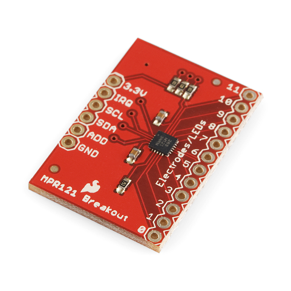
This is a breakout board for Freescale's MPR121QR2. The MPR121 is a capacitive touch sensor controller driven by an I2C interface. The chip can control up to twelve individual electrodes, as well as a simulated thirteenth electrode. The MPR121 also features eight LED driving pins. When these pins are not configured as electrodes, they may be used to drive LEDs.
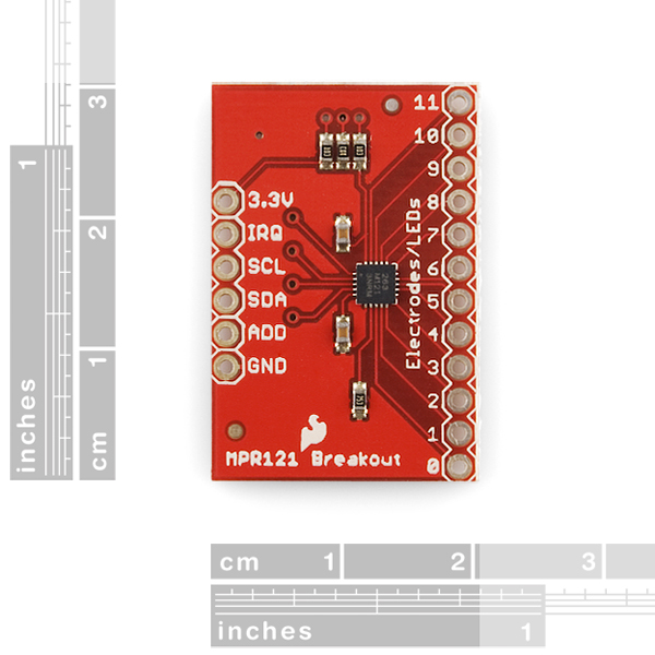
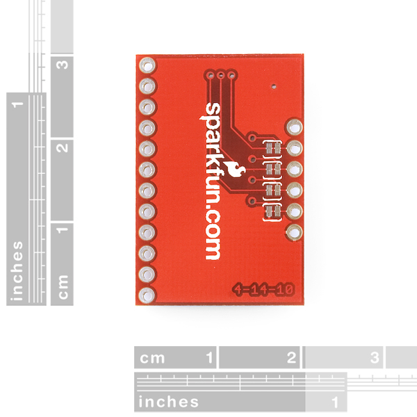
There a four jumpers on the bottom of the board, all of which are set (closed) by default. An address jumper ties the ADD pin to ground, meaning the default I2C address of the chip will be 0x5A. If you need to change the address of the chip (by shorting ADD to a different pin), make sure you open the jumper first. Jumpers also connect SDA, SCL and the interrupt pin to 10k pull-up resistors. If you don't require the pull-up resistors you can open the jumpers by cutting the trace connecting them.
There is no regulation on the board, so the voltage supplied should be between 2.5 and 3.6VDC. The VREG pin is connected through a 0.1uF capacitor to ground, which means, unless you modify the board, you can't operate the MPR121 in low-supply voltage mode (1.71-2.75VDC).
- Schematic
- Eagle Files
- Datasheet (MPR121QR)
- Example Code (ATmega328)
- Hookup Guide
- Freescale's Product Page (for Application Notes, etc.)
- Bildr Tutorial
- GitHub
SparkFun Capacitive Touch Sensor Breakout - MPR121 Product Help and Resources
Core Skill: Soldering
This skill defines how difficult the soldering is on a particular product. It might be a couple simple solder joints, or require special reflow tools.
Skill Level: Noob - Some basic soldering is required, but it is limited to a just a few pins, basic through-hole soldering, and couple (if any) polarized components. A basic soldering iron is all you should need.
See all skill levels
Core Skill: Programming
If a board needs code or communicates somehow, you're going to need to know how to program or interface with it. The programming skill is all about communication and code.
Skill Level: Competent - The toolchain for programming is a bit more complex and will examples may not be explicitly provided for you. You will be required to have a fundamental knowledge of programming and be required to provide your own code. You may need to modify existing libraries or code to work with your specific hardware. Sensor and hardware interfaces will be SPI or I2C.
See all skill levels
Core Skill: Electrical Prototyping
If it requires power, you need to know how much, what all the pins do, and how to hook it up. You may need to reference datasheets, schematics, and know the ins and outs of electronics.
Skill Level: Noob - You don't need to reference a datasheet, but you will need to know basic power requirements.
See all skill levels
Comments
Looking for answers to technical questions?
We welcome your comments and suggestions below. However, if you are looking for solutions to technical questions please see our Technical Assistance page.
Customer Reviews
3.8 out of 5
Based on 5 ratings:
1 of 1 found this helpful:
Good Value, Will Buy Again
This board gets the job done. I've used it with a number of different objects as the electrodes. The thresholds in the header file need to be adjusted depending on the object used, but generally it can be dialed in well. With some metal pieces, I've found the sensing to be a little finicky. If the capacitance goes down from the initial state for example, the board reports touches on that electrode till it is reset. In a fixed electrode setting however, this situation can be avoided, and it functions properly. All in all, it's pretty effective for $10, and I will continue buying more as the need arises.
1 of 3 found this helpful:
This chip isn't in regular production
Why is this product for sale? The MPR121 is a legacy part. I wasted my time building a PCB and programming this in Arduino. I had to start over with a Microchip part.
Sorry you ran into problems with this. I believe the MPR121 only went out of production about a month ago (it will still technically be made for the next decade or so by a new supplier but at a cost premium to allow manufactures to phase it out of devices). We are currently still selling this as many customers only need a one time solution which this works well for and we continue to have stock. We are looking into replacements, but have not come up with anything yet.
Excellent, easy to use sensor
Very intuitive sensor. Enough information available online that I (as a novice to this) was able to interface this easily with Arduino and modify the available code to suit my needs. Highly recommend and would buy again.
Is there a replacement for this?
I'm currently building a narrating panel where the person touches a spot to hear a narration, and this part is perfect for that, I have one but wonder if there is a replacement?
Unfortunately we discontinued this and don't have a similar replacement. There are other manufacturers that make breakouts for this IC thouugh. Just to an internet search for 'MPR121' and several options should appear. Good luck with your project!
OH NO! I've been blindly working on a board based around the MPR121 for the past half a year or so. Now I've come to making my BOM and I find out it's out of production. This is literally the worst news I've had in ages, so much time and work wasted.
Is this really being taken out of production? Is no one else going to be manufacturing this? If it Is all true; is there anything I can replace this with that can be near enough a drop in replacement?
Please help!
It seems production of the mpr121 was transferred to resurgent, so have you got more information ? and can I hope future production ? How the engineer from adafruit or bare conductive manage with this transfer... I would prefer your breakout board with only few components ;-)
The production for the mpr121 was indeed transferred. Doing so also increased the cost to the point where this board really wasn't feasible to produce which is why we've retired it. I'd check out some of the other capacitive touch options available, but I don't foresee anyone having breakouts based on this available for long.
The features I love in nxp freescale mpr121 is near proximity detection with low power consumption as low as 29uA for the 12 inputs (16ms response time). Best replacement part I found at the moment is Cypress CY8CMBR3002 with (too much for designing a rf touch sensor node I want) with 22uA per sensor input (120ms response time).
Just a thought here - I believe one must first upload the sketch and THEN connect the MPR121 breakout to the Arduino. This is in case there is another sketch already running, which might be using the I2C pins as regular outputs. If so, it will damage the MPR121 with 5V on the I2C lines !
Of course, also make sure your sketch does not use the I2C lines as I/O by oversight.
I work at the LAB at Rockwell Group, and we recently created a prototype that uses the MPR121 breakout board for proximity detection. We used Jim Bloom's tutorial and code from Bildr.com as the starting point for our work. Then we spent the better part of two days going through the data sheet and application notes to figure out how to activate and configure proximity detection.
We wanted to share our Arduino here in the hopes that it will be useful to other people in the Sparkfun community. I've posted more information about how to use the MPR121 for proximity detection here: http://julioterra.com/journal/2012/12/proximity-detection-using-mpr121-capacitive-touch-sensor/
I enjoyed reading about the Rockwell group and your work in particular, and thank you for sharing your experience. I wondered if you had any thoughts about my posting of earlier today (see below) with respect to adjustment of the touch and release threshold values for the board.
Whenever I read the register addresses 0x00 and 0x01, the OCVF bit is set to 1. In the documentation, it says that a value of 1 for the OCVF means an incorrect Rext resistor value. This resistor should be 75k ohms and I double-checked to make sure it is, but I still get this error flag. Any thoughts? Maybe something not even to worry about?
Actually, what I'm seeing is not the OCVF bit set but when I read from registers 0x00 and 0x01 I acquire the same data for both. I'll have to dig in deeper.
i'm also seeing this problem on the rasberrypi
reading registers 0x00, 0x01, or 0x04 all turn up the same data (0x00)
the only way ive found to get elements 9 thru 12 is to read 0x00 in word mode (2 bytes in the same read)
but the larger read to get 32 bytes at once (the only way to get to 0x04) crashes the system solid
When will it be in stock enough quantity? This product is very popular here, but I couldn't buy it because of lack. Could you please have it more? By back order, it costs more. And we can't get order for it, because we can't know about when it will come.
When can I buy it more? it remains just 1 in stock.
You can buy more than one, it will just become a back order. Contact customerservice@sparkfun dot com if you have questions about this.
dumb question but can this be used to create a touch screen?
hello Im a noobie and I wonder If we can hook up 2 of this breakout to a single arduino, and from the hookup guide I guess we can set it on irq 4? Thanks
Would it be possible to use this breakout board with a Fio Xbee..? If yes, is there any specific to think of when hooking up and / or configuring the Xbee?
is it possible to sense "where" a object was touched e.g. the touchpoint on a string?
The MPR121 is good at detecting touch events but we've had difficulty getting proximity to work reliably. Got a little fed up and decided to explore other controllers. We found a better one that can also detect gestures and decided to build a board around it hoping it might help other hardware enthusiasts.
You can check out our board (Hover) here: www.justhover.com
Im working on hooking this up to a raspberry pi through the GPIO ribbon. Everytime I hook it up, the 3.3v pin heats up, the pi gets squirly and needs a reboot. Anyone have this issue?
I am trying to use the the El Escudo Dos with the capacitive touch sensor MPR121, and I have hit a snag: Is there any way for me to use digital pin 2 as an interrupt pin with this sheild? I am afraid I’ll fry whatever I plug into pin 2. Can other digital pins, or analog pins for that matter, be configured and used as the IRQ pin?
One idea is to cut the male stackable header on pin D2, in use a 90 degree pin to my bob. But I'd rather not change the El Escudo if I don't need to.
Any suggestions appreciated.
On another note... Also, if I understand correctly, if I short SJ1, the EL wire will run brighter on 12V DC ? Thank you for your help. John
On the EL Escudo, pins D2 and D3 are used for EL channels A and B, but you should be able to use them as interrupts if you're willing to forfeit those EL channels. Just set the desired pin to be an input in your code; the external interrupt will turn on the LED in the optoisolator (turning on that EL channel) but it won't fry anything - there are optoisolators between the high voltage and the Arduino.
D2 and D3 are the easiest interrupt pins to use because support is built into Arduino, but you can also configure A0-A5 as digital inputs and use a pin-change interrupt library.
SJ1 bypasses the regulator on the EL Escudo; if it is open, the inverter will be fed with 3.3V. If you close it, the inverter will be fed with whatever is on the VIN pin. If you're using a 12V regulator, and have a 12V supply, definitely close that jumper.
Hope this helps, good luck and let us know if you have further questions!
The hookup guide shows this connected to an Arduino Uno but the description here says that its a 3.3V device. Can I hook this up to the Uno directly? Are the MPR121 pins 5V tolerant?
The I2C pins can be hooked up to a 5V Uno. Just make sure to keep your power lines connected to 3.3V.
Has anyone here successfully used a potentiometer to update the thresholds dynamically? I am trying to make the sensitivity adjustable with two potentiometers but I don't seem to be able to update the threshold values at runtime. I think it because the values are "read only" when the sensor is in "Run mode".
I am calling set_register(0x5A, ELE_CFG, 0x00); before I try to update the values and then set_register(0x5A, ELE_CFG, 0x0C); after I update.
Does not work for me and I am sure I am misunderstanding something.
Anyone willing to share some experience regarding this scenario?
So, starting from the code in github (https://github.com/sparkfun/MPR121_Capacitive_Touch_Breakout/tree/master/Firmware/MPR121Q/Arduino%20Sketch) I've been building an easier to use library for my personal use (I'll probably submit it at some point). I've read through some of the MPR121's datasheet, and want to try reading some direct register values from the chip, however its not clear to me how to do that using the Arduino Wire library. Anyone have pointers on how to do that?
I used Julio Terra's code and received a lot of errors, after some modifications, it works now pretty well. The proximity settings just need to defined before you run the code. It is still buggy though.
Really pleased by this tutorial, thanks for your continued efforts to provide services beyond just selling components.
Glad to hear it! If we can ever improve, please let us know :)
Is a Fritzing part available for the MPR121 Breakout Board? In your "hookup guide" you can see a fritzing part...
https://learn.sparkfun.com/tutorials/mpr121-hookup-guide/capacitive-touch-sensor-breakout-board
I try to use this sensor with Pro Micro. To what pins of Pro Micro should I connect IRQ SCL SDA ADD ?
IRQ goes to any digital pin (if you follow the Bildr tutorial, they use digital pin 2), SDA and SCL go to whichever pins are SDA and SDL - check out the learn: Pro Micro & Fio v3 Hookup Guide, which has a nice pin mapping image - and ADD is left unconnected unless you want to change the I²C address
I'm working on my first Arduino project, which uses the MPR121 breakout board with an Indium-Tin-Oxide coated plastic sheet as the proximity detector. I based my code on that available in the Bldr tutorial (http://bildr.org/2011/05/mpr121_arduino/), which appears in turn to use large chunks of the Example Code provided here by Sparkfun. To my pleasant surprise, it all worked, until I installed the ITO plastic pad in its final location, and now the system responds as if the pad is continually being touched. I anticipated this, and assume that the solution is to adjust the touch and release threshold values (TOU_THRESH, REL_THRESH). However, there is no clear guidance as to how to do so, and I find the Freescale documentation daunting to say the least. I'm further confused in that the touch and release thresholds are set, respectively, to 6 and 10 in one example, and 15 and 10 in another (that is, the order of their magnitudes are reversed). I can certainly plunge into lots of experimentation to sort this out, but thought I'd post here first to see if I can cut to the chase by building upon the advice of someone who knows this product well. Thanks in advance for sharing any experience or providing helpful guidance.
Put the plastic pad on first, and then fire up the MPR121 and see what happens. I had the same problem with a different set up and that fixed it.
Has anyone experienced fluctuation of the pin 11? I can't get a stable value from any of the 8 boards I have. I really believe Sparkfun's design of this board is to blame, since pin 11 routing is very close to the 3.3v one. I've tried with different I2C bus frequencies, from 20kHz to 400kHz, hoping this would change any noise inducted on the pin, but it didn't.
Yes, Sometimes it works sometimes it does not.
Hi ....... I have two MPR both were working till last week but today when i try to operate them they didn't response. I checked every thing 5 times( shouldering, connection same as in example, MPR example, baud rate everything)(http://bildr.org/?s=mpr121). Is there any way to check them. Whether they burn out or ok.. Can anyone help?
How well does this sensor perform on wet environment?
How wet? if it is just moisture, I believe it will work fine, but in the rain it certainly will not.
hello, on the Application Notes I noticed that the pads can be arranged as a 5x7 matrix, so you can get 35 inputs only using 1 chip. Is that true, and if yes, how can this be accomplished? many thanks Dimitri
I am trying to interface the MPR121 with 5v 8051 micro controller. I have also purchased the logic level converter. Should i used pull up resistors for the IRQ pin even if i use a logic level converter ?
Just use a MOSFET for each of the MPR121 - 8051 lines and pull up resistors, like explained in NXP application note AN10441 (http://www.nxp.com/documents/application_note/AN10441.pdf)
Is the actual MPR121QR2 chip included on the breakout board, or is this product just the breakout board WITHOUT the chip? I see the chip on the image, but I'm paranoid parrot so I gotta ask anyway...
The chip is actually included on the board.
I need to use 3 of these devices, 1 for a 4x3 keypad and 2 others for 14 buttons. I understand the addressing of the chips but in the arduino example I dont see where I access the 0x5a to change it to 0x5b, etc. also now I have 3 interrupts to handle and of course I'm using a 328p which I believe only has 2 interrupt pins? any ideas on that? I was thinking about putting the 2 into an OR gate and just reading both chips when the irq is triggered. thanks.
I want to create the beetbox using the Raspberry Pi and this controller. I am uncertain how to physically connect MPT121 to the Raspberry Pi. I apologize for such a rudimentary question.
I have multiple MPR121 boards which I want to connect to a PCF8575 I2C Expander, then to an arduino. However, I don't know how to connect them. Can anyone help?
If there's anyone who's getting absolutely nothing out of this module: the unit I received had wonky soldering on the chip. The SCL pin wasn't connected properly. It took me half a day and a microscope to figure this out. I think we deserve better than bad reflow for $10! (the chip's only a dollar!)
Would you guys be willing to share the eagle files for this breakout board ? Thanks ! -jc
Of course! Here ya go. Also added a link up top.
Jimbo, thanks so much.. in the 5 days since I asked I've become (I think) a convert to Fritzing.. would you or anyone happen to have a library model for the MPR121 breakout board already done up in Fritzing ? The new library editor in Fritzing is not yet complete.. and there doesn't seem to be a good way to import from eagle.. Any pointers appreciated. Thanks ! -jc
Anybody know a way to increase sensitivity beyond setting touch threshold to 0x01? I need to run more then 10' long wires to 12 electrodes and I am getting no response from the MPR121. Is there a way to fine tune the filters / threshold? Any help in this regard would be appreciated.
Second this question. I am running up to 25 ft. to 20 different touch points - and the MPR121 does not seem to read the levels.
Hi. Refer to section 5 of the datasheet, where they explain one by one the registers of the MPR121, including all the built in filters, namely Baseline Value (0x1E~0x2A), Baseline Filter (0x2B~0x40), Touch/Release thresholds (0x41~0x5A), and Debounce (0x5B). I don't know what the application end is, but with based on my experience, I would suggest: 1) put the MPR121 as close as possible to the pads; 2) use the thinnest possible wire to connect the pads to MPR121; 3) Avoid any other wires close to the capacitive wires for a couple of inches, specially digital connections with high frequencies; 4) avoid any other conductor materials close to the capacitive wires.
My project requires measuring capacitance for 96 electrodes. Given that the MPR121 only has three addresses, my plan is to connect eight of these to a PCF8575 I2C Expander. Does this make sense? If so, could someone help this newb on how to properly connect them?
Have you already tried this? I want to connect multiple mpr121 boards to the PCF8575 I2C Expander, but have no idea how to connect these. Anyone?
Hi. Yes, it makes sense, and I have done it already. MPR121 has one ADDR pin which can be connected to VCC, GND, SDA and SCL, each assigning a different I2C address. So, for example, if you connect eight MPR121 on the same I2C bus, you should connect all the SDA together, and all the SCL together too. Now you have eight ADDR pins, so, you can connect each of them to a different pin of your microcontroller. In the startup routine on the microcontroller, reset all the GPIO pins connected to the ADDRx. This will assign all the MPR121 the address 0x5A. This means you should never send a package to this address, otherwise all the ICs will try to respond at the same time, crashing your I2C bus. Instead, every time you want to communicate to an MPR121, you must set the corresponding ADDR pin, assigning address 0x5B only to that MPR121, then you send the I2C packages to address 0x5B, read whatever you need, and when the communication is over, it is necessary to restore the 0x5A address to that MPR121, by reseting the respective ADDR pin.
Ah, and don't forget, in this specific board, to cut the jumper on the backside of the PCB that connects the ADDR pin to VSS.
I have this module and a Leonardo Board , does not work with leonardo board. however it works with uno and others. has anybody find a fix for this problem.
According to this http://www.flickr.com/photos/johngineer/7329403498/in/photostream/lightbox/ there is a problem with using pin 2. I assume because it's physically connected to the SDA pin. I tried changing the bildr example code to use pin 4 and it worked! see also: http://forum.bildr.org/viewtopic.php?f=29&p=5808
Folks, I'm using an MPR121 + arduino in a musical device and its working quite well. I'm doing trial and error changes on the settings for touch and release thresholds, auto calibration modes and debounce settings. I have it working pretty well, but I'm now trying to do some final tuning in which I'm trying to balance touch sensitivity to noise sensitivity and latency. I've read the MPR121 tutorials.. but still am struggling a bit. While I'm successfully writing the config registers, I can also read the key press register (0x5A) One thing I have not figured out how to do is to read the other internal register values (eg. the raw sense value, the current baseline, etc ) on the device and print them to the serial monitor in the Arduino. I've tried using the same scheme to do an I2C read for other registers.. but they always come back 0's. Does anyone have a code fragment that shows how to read these register values.. ? Also.. does anyone have any suggestions on a process to optimize the the touch/release thresholds for a specific configuration ? Ive tried to work things out from the mfg tutorial at http://cache.freescale.com/files/sensors/doc/app_note/AN3889.pdf but its a little academic..
Any help / guidance on this would be much appreciated. Thanks ! -jc
Hi John,
I'm having the exact same issue. I'm trying to read out the raw sense value. I have trouble figuring out how to set the registers (0x04~0x1D) to get a readout. If you have managed to figured it and are willing to share your solution, that would be great!
I want to use MPR121 to sense the capacitance. All the tutorials are about touch sensing, anyone can tell me how to make the output of MPR121 as specific voltage to calculate the capacitance. Many thanks.
You can access the Electrode Filtered Data Register (0x04~0x1D), section 5.3 of the datasheet, to get a proportional value of the capacitance.
For an installation I am making I need about 100 sensors. I am thinking about connecting 8 MPR121 boards. However, how many arduino's will I need to connect this? And will it be possible to read the data in Max/MSP?
You could connect all the MPR121 boards onto one I2C port, but you will need an I2C Port Expander in order to address each sensor individually.
Does anyone know if I can use this chip as pressure sensor, like in this video http://www.youtube.com/watch?v=1UBrjMzprU8&feature=plcp ? Thanks in advance
I can't get it to work. It always hang on the first Wire.endTransmission(), as if there was a wiring problem, or the I2C address was wrong. I checked the soldering and the wires, and they seem to be correct. Has anyone had the same kind of problem ?
Anybody know a way to increase sensitivity beyond setting touch threshold to 0x01?
with the capsense() example, (http://www.arduino.cc/playground/Main/CapSense) a resistor of 10M made each electrode proximity sensitive.
I need to run really long wires to 12 electrodes and I am getting no response from the MPR121.
I created a touch volume control slider wheel following the Bildr tutorial and using a digital potentiometer. Here is a video of it in action.
http://www.youtube.com/watch?v=9ZmCSceEOb0&feature=share&list=UUWsBOpI7xEaGsXV33ONulSw
Is this as good as the CapSense from Cypress? I want to make a slider (or two), and the SmartSense feature on the CapSense sounds promising, but the hardware/software assembly is easier with this.
No, Cypress CapSense solutions are much superior. There debugging and tunning tools are excellent to work with.
I'm looking at the datasheet and it says it only tolerates Vdd+0.3V on SCL and SDA pins (so basically a maximum of 3.6V). However interfacing directly with an arduino means the arduino pulls those pins at 5V.
Question is, is this stable in production? Is there any circuitry recommended to couple this board to an arduino?
As a newbie, I find this thread confusing. I am attaching my MPR121 board to my Arduino Uno via the 3.3V pin supplied on the Uno board, as is done in the Bldr example cited above. Is there anything I have to worry about? Do these comments about 3.3 vs 5V apply only to some other hardware configuration, as I hope?
The Arduino Wire library does a lot of things right, and one thing wrong. The right things are that it implements a correct I2C interface that grounds the lines for 0, and sets them to high-Z inputs for 1, so it will work correctly for 3.3V I2C parts. The wrong thing is that the library turns on the weak pull-up (WPU) resistors by default, which connects the I2C lines via 20K resistors to 5V. There's a fair amount of controversy over this, and the library will likely change at some point in the future to at least make this non-default behavior. It's also possible to modify the library yourself to turn the WPU resistors off.
But in practice, the WPU resistors are so small that they can't transfer much current back to the device (in fact they're so weak that they don't really make very good I2C bus pullup resistors). And, if other I2C bus pullup resistors to 3.3V are present, as they are on this board, those will overpower the WPU resistors. For example, this board has 10K pullups to 3.3V. If you parallel those with the WPUs to 5V, no more than 3.8V will appear on the I2C lines. This is above the recommended maximum, but not as bad as putting 5V straight onto those lines. I've personally never had a problem running 3.3V I2C parts on a 5V Arduino when using outboard I2C pullup resistors to 3.3V, but of course your mileage may vary.
Is there a schematic available for this board?
There is now! Link.
Thanks!
The board detects the touch, but the interrupt pulled low permanently and does not come back to high. Can anyone tell what is the problem or where could be the problem?
Yes.., but where are the actual sensors that I can connect to it??
You make your own. They're typically pads on a pcb, or a matrix of Indium Tin Oxide (or Aluminum Zinc Oxide) traces that are deposited on the inside of the glass covering a display screen, as in the case iPads, iPhones, smart phones, etc.
All you really need is a wire connecting to a conductive material. I'm currently using thin copper sheeting. Some people use aluminum foil with an alligator clip connecting the foil and the wire. It all depends upon your application.
I have an inkling that my sda pin on my arduino is not working. I used to be able to get the mpr121 up and running with ease on my arduino, but it no longer sends any data when I press the electrodes. I have tested the voltage and ground pins, however not the irq so that is still a possibility. But when I ran a program to set each analog input as an input for a push button, the push button only got a response on a5 and A0, leading me to believe a4, the sda pin, is no longer working. How can I verify this/fix this?
If you have access to an oscilloscope you could look at the signal coming off SDA. Otherwise, I would suggest trying to write a value to a register on the sensor and then read it back. If it's coming back as 0x00 or something other than what you wrote to that register, then you can definitively make the statement that something is amiss.
what does the IRQ pin do?
From the datasheet:
Then, without a microprocessor, standalone, the IRQ pin acts like a switch? A low level output until untouch one of the 12 buttons??
It only outputs a pulse when any button is pressed and a pulse when any button is released. It does not output a constant pulse from the time the button is pressed to the time the button is released. The pin's primary purpose is to tell the microcontroller when there is a state change so that microcontroller knows when to get the data from the MPR121.
Thank you!!! I really wanted a constant pulse without a microcontroller.
I'm going to make a board for this IC with just a microcontroller and the capacitive touch IC on it. That way, the microcontroller can be programmed to output constant pulses for each button.
That would be great. I am going to interface it with a schmitt trigger, maybe in that way I can avoid the use of a microcontroller.
You could also look elsewhere as there are touch controllers that output directly to pure digital values when pressed rather than using i2c
This is awesome! (****starts thinking about a DIY Percussion controller...****)
(****creates public wishlist****)
Is it possible to use several of these connected to one microprocessor?
Yes, but you'll need to very carefully cut one of the traces on the back of the board. On the bottom of page 3 of the datasheet they specify what's required to change the address. Just connect the address pin to VSS, VDD, SCA or SCL to change it.
I checked out the spec sheet and it is still not super clear how to daisy chain them. I need about 30 touch sensors for my project, can you help me?! is there code for this anywhere?
With some I2C devices there are more addresses available, but this chip has only has three. So, you're limited to three per I2C line. It's possible you could use an arrangement such as two 8 channel multiplexers, one for the data line and one for the clock line, and have 3 devices on each channel of the multiplexer.
For what reason do you need so many sensors?
It is actually 4 different addresses!
i believe someone adapted the AVR example to function on an arduino.<br />
ah here it is:<br />
<br />
http://www.prize-pony.com/blog/electronics/using-a-mpr121-with-arduino/<br />
<br />
its only an adaptation but it works for me.<br />
i got mine today and im currently optimizing the code for the arduino. for instance im adding support for the arduino interupt. i might try to create a library for this later on <br />
<br />
regarding the Epoxy Question:<br />
im not certain. i have had that electrodes work as capacitive sensors. il check a bit
The Wire library for the Arduino is not so great, and I would recommend directly using the AVR example.
As far as the epoxy is concerned, it's fine. It has a dielectric constant of approximately 4, but your biggest issue will be air bubbles trapped inside the epoxy. If you can get those out you'll have fairly uniform results. For proximity sensing, your best bet will be to have a large electrode, the largest charge current (63 uA) and the largest charge time (128 ms) of this sensor. If you have big enough electrodes, you need not use the proximity sensing mode of this sensor, which essentially ties all electrodes together to act as a proximity sensor.
For a beer pong table, if you expect to detect the ping pong ball when it lands inside the cup, forget it. The change in capacitance would be so small that you wouldn't be able to separate it from the noise. A full cup verses an empty cup, however, is doable. The calibration is the hardest part in working with these sensors.
It would be awesome to see a tutorial on how to use this with an Arduino and some homemade buttons. I'd like to use this to make a beer pong table like this one, http://www.youtube.com/watch?v=j4-ZTZNe2eM. Does anyone think this would work through some epoxy?
This should help http://www.eetimes.com/design/analog-design/4009622/The-art-of-capacitive-touch-sensing