- Home
- Product Categories
- Arduino Shields
- SparkFun microSD Shield

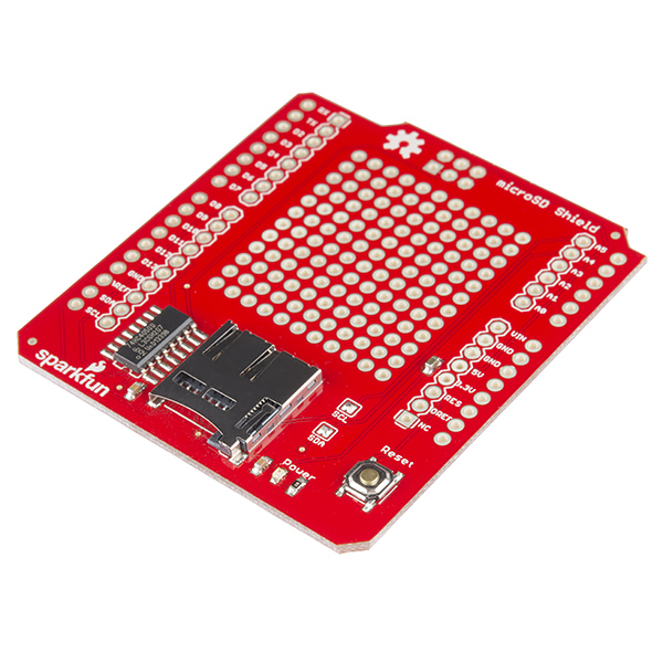
SparkFun microSD Shield
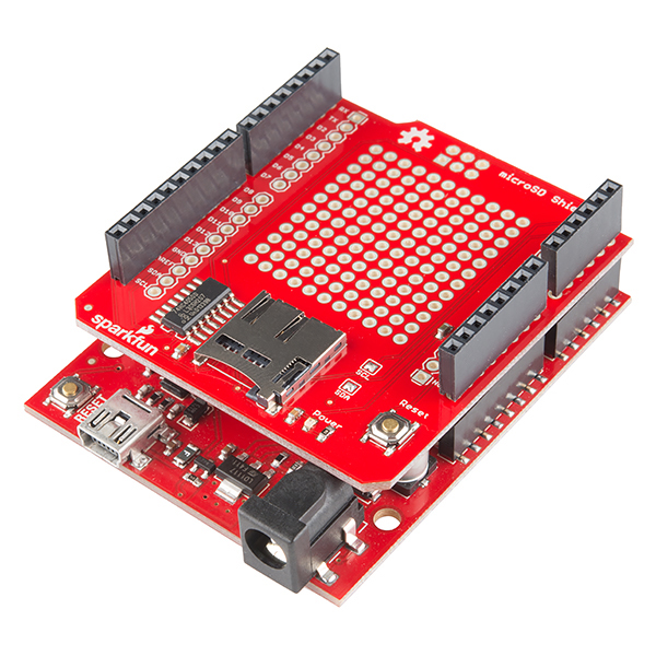
Running out of memory space in your Arduino project? The SparkFun microSD Shield equips your Arduino with mass-storage capability, so you can use it for data-logging or other related projects.
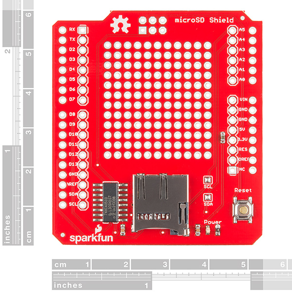
Communication with microSD cards is achieved over an SPI interface. The SCK, DI, and DO pins of the microSD socket are broken out to the ATmega168/328's standard SPI pins (digital 11-13), while the CS pin is broken out to Arduino's D8 pin. If you decide to use one of the many open source FAT libraries (like FAT16 or SDFat) make sure to change the code to reflect the location of the CS pin.
Most libraries assume the CS pin is connected to D10; this will have to be changed to D8. Also for the libraries to work pin D8 will have to be set as an output in the 'setup()' section of your sketch. The shield also includes a large prototyping area with a 13x12 grid of 0.1" pitch PTHs.
This shield comes populated with a microSD socket, red power indicator LED, and a reset button; but it does not come with headers installed. We recommend the Arduino R3 Stackable Header Kit.
- Schematic
- Eagle Files
- Hookup Guide
- SD Library (FAT16 and FAT32)
- Example Sketch
- GitHub (Design Files & Example Code)
SparkFun microSD Shield Product Help and Resources
microSD Sniffer Hookup Guide
August 4, 2015
A basic introduction to working with the microSD Sniffer.
GPS Geo-Mapping at the Push of a Button
September 27, 2019
Let's ramp up our GPS tracking skills with KML files and Google Earth. We'll make a tracker that logs location and allows us to visualize our steps with Google Earth.
MicroSD Shield and SD Breakout Hookup Guide
March 25, 2015
Adding external storage in the form of an SD or microSD card can be a great addition to any project. Learn how in this hookup guide for the microSD shield and SD breakout boards.
Arduino Due Compatibility
We have had customers confirm this shield will work on an Arduino Due. You will need to add a 2x3 Header like this to the shield for SPI over ICSP and do not use pins 11-13.
Core Skill: Soldering
This skill defines how difficult the soldering is on a particular product. It might be a couple simple solder joints, or require special reflow tools.
Skill Level: Noob - Some basic soldering is required, but it is limited to a just a few pins, basic through-hole soldering, and couple (if any) polarized components. A basic soldering iron is all you should need.
See all skill levels
Core Skill: Electrical Prototyping
If it requires power, you need to know how much, what all the pins do, and how to hook it up. You may need to reference datasheets, schematics, and know the ins and outs of electronics.
Skill Level: Rookie - You may be required to know a bit more about the component, such as orientation, or how to hook it up, in addition to power requirements. You will need to understand polarized components.
See all skill levels
Comments
Looking for answers to technical questions?
We welcome your comments and suggestions below. However, if you are looking for solutions to technical questions please see our Technical Assistance page.
Customer Reviews
4.1 out of 5
Based on 10 ratings:
1 of 1 found this helpful:
Arduino Due
The Arduino Due does not use pins 11-13 as SPI pins, so the shield won't work if you connect them. Instead, you have to connect the ICSP header, that is the Due's only SPI breakout, and leave pins 11-13 unconnected.
Having sorted that out, the shield works great!
1 of 1 found this helpful:
Totally functional, and nice to have the prototype area.
Good documentation allowed very little setup time. The prototype area I used for a few pushbuttons and an RTC. One suggestion for improvement, the SD socket should be a little closer to the edge of the board. With a SD inserted, it takes a fingernail to depress it because it does not extend over the board edge. Because it's hard to grip the SD, several times the spring action has launched the card about a meter.
3 of 3 found this helpful:
The MicroSD Shield
The MicroSD shield worked fine on an Arduino Uno but did not work as delivered with the recommended header set on the Arduino Mega2560. I had to order the six pin female SPI header and it then worked on the Mega. Here should have been documentation stating what was needed for it to operate with the mega type boards.
4 of 5 found this helpful:
Doesn't seat properly to UNO
Using the stackable header kit, the micro SD shield does not seat correctly on the UNO-R3. The back of the unit (roughly where the Sparkfun logo is shown on the shield) hits the back of the USB port. I used a dremmel tool to cut a 1/8" notch on the board to accommodate the USB port, but the other side (where the work "Power" appears) hit the power port for the barrel power plug. I ended up setting the whole unit about 1/8" higher to get it to sit straight. This creates a stability problem since I have mounted an accelerometer on the shield so it needs to be stable and sit straight to function properly.
Easy path to data logging...
I purchased this to learn data logging basics. There was plenty of room to layout a baro/temp breakout board, connectors for GPS, Radio, analog sensor and wire everything within the shield. The library is easy to understand and use. Flawless product! BTW... the stacking issue is easily solved by installing "bottom headers" (the thin stip of holed plastic that holds normal header pins together). This simple addition prevents the shield from resting directly onto of the top of the Arduino's female header rows.
Cure for Arduino data memory limitations
microSD shield works well with a 2 Gig micro SD when running on a Uno R3 in a data-logging program. Data is easily saved as comma-separated variables, which can then be moved to Excel without problems. The program I'm using reads 4 A/D channels and a time stamp, and max data rate is about 35 lines of time stamp + data per second.
Only glitch I noted is that there are occasional pauses in the recorded data, when 3 or 4 lines are missed before the program resumes. SD.h housekeeping, I suppose. Otherwise, 5 stars.
Handy, but ...
Nice, handy shield, but it has one limitation: The CS pin is hardwired to pin 8. Normally, if I had a conflict with another shield I could (reluctantly) cut a trace and tack on a wire if necessary, but the trace on this is extremely small. This scenario is not uncommon, but totally frustrating. It would be nice if the PCB had a row of "solder-bridge jumper" pads, where any one of several pins could be used, and it wouldn't cost a single penny extra to manufacture. All shields should have this type of option, to the extent practical.
Hi, Thanks for the suggestion. It would be really a cool feature for shields to include a jumper for relocation of pins. There is a hardware option that can also help you with this. It’s the go between shield and it lets you easily adapt the pinouts of your shield to change things up.
Handy board but lacks mounting holes
This Arduino shield lacks the standard Arduino mounting holes. Drilling the holes to match a UNO requires cutting a pin off of the Reset switch and patching some traces. There is plenty of space on the board so I don't see why these holes we left off.
Hi, We don't include mounting holes with most of our shields. Sorry if that is a feature that you need.
0 of 1 found this helpful:
Best thing I ever ovned
Works fine
Hi gang, handy shield one can quickly grab to get an SD slot going. Note that for a battery powered quick project where I log something every few hours I had to do a mod. After putting this shield on my custom shield stack, the current draw was higher than what I expected. I took out this shield on its own, and it was consuming about 3.2 mA if I hooked up just the power and ground: photo Not a big deal for so many applications, but I'm chasing those milliamps. The level shift IC has three floating inputs. Tying those to ground, via the ground pin on the ICP header holes, and that got it right down to basically zero: photo So if you need those extra mA's conserved, this can be a way to achieve that if you use this shield. Now my overall stack is down to where I need it for long battery life, 624 uA for my (modded) Redboard, the microSD shield, HX711 strain gague amp, and an RTC I threw on photo.
I tried using the MicroSD Shield with the recommended Arduino R3 Stackable Header Kit installed on an Arduino Uno SMD. I then tried to run a sketch for data storage and got a failure to initialize SD card message on the serial monitor. I then tried all SD examples available on the Arduino IDE, those provided on the SparkFun site and even some found online. All produced the same failure to initialize SD card message. I then tried the shield on an Uno R3 and it worked fine.
According to the information provided on the Arduino site there are no differences between the R3 and SMD editions, so I thought my SMD was shot. Then I read a couple of comments on the SparkFun site about the MicroSD Shield not being able to be used with some Arduino types unless the ICSP header was installed. I made up a header, soldered it onto the MicroSD Shield and placed the Shield back on the Arduino. Voila, it worked like a charm! I would have saved a lot of time and frustration if I had known that the SMD required the ICSP header and the header was included in the kit.
Hello, would this SD board be able to stack with/ be compatible with the sparkfun Arduno-Vernier Interface shield ( with BTA/ BTD inputs)?
I bought this board (from local market) to showcase my free and fast Sqlite Micro Logger, which can log sensor data into Sqlite database on a Micro SD card using this shield and Arduino Uno. Check out the pictures at https://github.com/siara-cc/sqlite_micro_logger_arduino.
I don't understand JAMac's complaint (see reviews) about the board hitting the USB connector and power port. There's absolutely nothing on the bottom of the shield, so ANY PCB should hit the USB connector and power port. Maybe use longer headers?
For clarification, this is an issue (or non-issue) that comes into techsupport a lot. With headers unsoldered a shield will sit on the Arduino headers and make contact with the USB and power jack connectors. People often stop here and say it doesn't fit. If you solder the stackable headers on it actually lifts the shield up about 1/8" allowing the board to clear the connectors. All Arduino shields have the same footprint (with a few exceptions) and so this applies to all shields. Rest assured all of our shields will fit just fine on an Uno with the stackable headers installed. Also, never Dremel or cut your board unless you know what you are doing. In many cases there are traces on the board you might end up cutting which will destroy the functionality of the board.
Is it possible, whatsoever to have this board running while simultaneously running and i2c bus? I have disconnected the jumpers to 4 and 5 as suggested on the datasheet, however to no avail. I have been at this for a very long time and I'm fairly certain that it is not possible, however I need to be sure
I have been using these shields to log data on vehicles. They stay on vehicles for days at a time. Lately, I have had a couple stop saving data. Could it be the shield? Are there parts that could burn out from being powered on for up to a week at a time?
I'd love to see this shield with a RTC on it. Since most of the cost is for the production of the PCB and logistics, the extra cost for the RTC + battery holder will only be a couple of dollars.
NXP PCF8583 please! The PCF8583 is superior to the DS1307 Adafruit chose in any way, and it's cheaper too.
Update: Forget the 8583. The PCF85263A also features watchdog and stopwatch functions, consumes less power, AND is even cheaper.
Can one of the mini modular breadboards fit on the prototyping area of this shield?
I have a question: to make the shield work with Arduino Mega 2560, could I make some hardware changes instead of modifying the SD library? From the schematic, it looks like it might work if I use some sort of headers to connect the Arduino Mega 2560's ICSP pins to the shield ICSP holes, then cut the shield's pins 11, 12, and 13.
I think if I make these changes I should then be able to use the standard SD library, with pinMode(8, OUTPUT) and SD.begin(8) in my sketch.
Is that correct? What headers should I use? Do you have headers that will plug into the ICSP 2x3 pins and extend them through the shield so I can do the same trick on a second, stacked shield?
Looks like you already figured out the library changes from your comment below. Regarding headers that will help shift the ICSP pins from the 2X3 header, you can use the Transmogri Shield between this and the Mega. You could then stack any other shields on top of this one.
The Transmogri Shield gives me good news and bad news: the good news is that my Sparkfun Wifi CC3000 Shield wifi works great with my Arduino Mega 2560 with a Triansmogri Shield in between (which was what I wanted to do in the first place: wifi + SD). The bad news is that with the Aruindo Mega 2560, the Transmogri Sheid,, the SD card on the Wifi shield doesn't seem to work, using either the stock SD library or the Sparkfun SD library with MEGA_SOFT_SPI turned on: The WebClientSD example fails to initialize the SD card. I think too many wires are being swizzled by too many things.
Fortunately, I have several things to try out yet - I'll let you know how it goes.
All better now: the problem was that I'd left MEGA_SOFT_SPI turned on, which double-swizzled the pins when I used the Transmogri Sheild, making the SD not work. The CC3000 library has its own SPI library, which doesn't seem to support soft SPI, so the Wifi was happy with the Transmogri shield.
In summary: For Arduino Mega 2560 rev 3 + the MicroSD shield, the MEGA_SOFT_SPI solution works great for me. For Arduino Mega 2560 rev 3 + the CC3000 Wifi Shield, I found it better to put a Transmogri Shield between the Mega 2560 and the CC3000 Shield, and leave the SD library untouched (left MEGA_SOFT_SPI as 0)
Thanks for your help - works great!
Glad to hear you got it working! Thanks for the update for other customers as well - I'm sure these hints will be helpful to others. Happy hacking!
Had to make some changes to make the shield work with Arduino Mega 2560. 1) In the SD library, in file Sd2Card.h, change MEGA_SOFT_SPI to 1 (rather than 0). 2) As described in the documentation, set pinMode(8, OUTPUT) and call SD.begin(8).
The change to MEGA_SOFT_SPI makes the SD library use pins 11, 12, and 13. The pinMode and SD.begin changes make the SD library use the required pin 8. I didn't have to make the recommended changes to pin 53 or pinMode(10, OUTPUT).
Brad, thanks for your comment.
I am trying to use the Arduino Mega 2560 with this shield (no transmorgi shield). New to programming and very unsure why it keeps failing the initialization test. I haven't soldered yet, but I want to be sure I have the right setup first. We still have power going to the shield.
Customer service told me not to connect header pins to 11-13 on the shield to the arduino; as well as to use a 2x3 female header to connect the ICSP to the shield, which we have done(should that be soldered as well?). Could you please go over how you got it to work in detail as I cannot get the test to work. I would greatly appreciate your help, as it seems we have similar setups.
For instance, how do you get and alter SD2card.h? Should all the pins be connected? What kind of code changes should be made to the standard SD card initialization test?
You will want to solder headers to all the pins (either the stackable headers or plain straight headers if you are not stacking on top of this). You will also want to solder the ISP header on the board. Without soldering them on you will probably not get a good enough electrical connection to be able to test anything. Solder all your headers on and if you are still having problems try emailing techsupport@sparkfun.com with any errors or problems you are seeing and they should be able to help.
Is there an update schematic for the version with the voltage converter?
Sorry about that confusion! That note was leftover from the old product page. The schematic posted is the current version. The voltage converter is the HEX converter chip shown in the schematic.