- Home
- Product Categories
- Audio Boards
- SparkFun OpAmp Breakout - LMV358

SparkFun OpAmp Breakout - LMV358
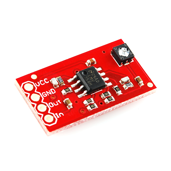
This is a simple 5V Op Amp breakout board, set up as a 2-stage amplifier with a gain of 100 (gain of 10 for each stage). The on-board trim pot sets the signal level between the stages, not the feedback path. The bandwidth is set to 15.9kHz by a pair of feedback capacitors, or over 100kHz with the caps removed. The LMV358 opamp can source up to 160mA and works well as a low impedance driver/buffer.
- Schematic
- Eagle Files
- Introduction to Op Amps with LTSpice
- Datasheet (LMV358)
- GitHub (Design Files)
SparkFun OpAmp Breakout - LMV358 Product Help and Resources
Core Skill: Soldering
This skill defines how difficult the soldering is on a particular product. It might be a couple simple solder joints, or require special reflow tools.
Skill Level: Noob - Some basic soldering is required, but it is limited to a just a few pins, basic through-hole soldering, and couple (if any) polarized components. A basic soldering iron is all you should need.
See all skill levels
Core Skill: Electrical Prototyping
If it requires power, you need to know how much, what all the pins do, and how to hook it up. You may need to reference datasheets, schematics, and know the ins and outs of electronics.
Skill Level: Rookie - You may be required to know a bit more about the component, such as orientation, or how to hook it up, in addition to power requirements. You will need to understand polarized components.
See all skill levels
Comments
Looking for answers to technical questions?
We welcome your comments and suggestions below. However, if you are looking for solutions to technical questions please see our Technical Assistance page.
Customer Reviews
5 out of 5
Based on 4 ratings:
1 of 1 found this helpful:
Good product
Great product. Came on time. Excellent purchase.
1 of 1 found this helpful:
Great little boards!
I have used these opAmp boards with both condenser & mems microphones, they're spectacular! Clean, high gain- Small package. Very simple, works perfectly. I'm using them for ultrasonic applications. Replaced the caps with 15pFs. Haven't tried with the caps completely removed yet, but definitely works to 100khz.
1 of 1 found this helpful:
Doing its job!
I tried this breakout for amplifying a MEMS microphone. It works great, even for ultrasonic applications after removing the C1 and C3 capacitors.
Great little amplifier
I am using it for a microphone amplifier and the board works very well. Very pleased with all of the products from Sparkfun and the Customer Service. Keep up the great work.
I tried to use this product to drive a speaker and quickly learned that the unit does not source 160 mA. A closer look at the datasheet shows that the LMV358 can only Source 40 mA. That's 1/16th the output power. Datasheet Page2:
• Changed output short-circuit current for sourcing from 60 mA to 40 mA .............................................................................. 8 • Changed output short-circuit current for sinking from 160 mA to 40 mA .............................................................................. 8
Please revise your description as I had purchased the part because I believed that it would be good to drive a speaker.
I'm not really getting along with the description here. What I'm trying to do is to input audio to my arduino via a 3.5mm audio jack in order to set up a servo according to the audio's volume. Is this the right board to offset the signal so I can read an all-positive signal?
Yes, the output will have an offset of about VCC/2. So you'll want to be measuring magnitude with your ADC from around that offset, not from zero, understand?
Thanks for the quick response! One more thing I didn't really get: As it seems the offset is fixed, what does the trim spot exactly do?
It's effectively a level adjustment sitchuated between stages.
I tried using it as a DC op-amp. I jumpered C5 and C6 but I think I am having offset issues like most people in this thread. I need a gain of 100 like this board. Can't I just make a simple 100 gain op amp using LM358 and RF=1M and Rg = 10k? Any issues I should be aware of? Thanks
Those numbers should work. Bear in mind that at Av=100, 50mV will give you full swing at the output, so you'll probably want use a potentiometer to calibrate your reference voltage to keep the device in the linear region and not railed (which is also to say that, yeah, you were probably having offset issues with the op amp board you've got).
Please make a tutorial for using this
How can I set this up for audio?
I'm buying a few of these to save time and space with some audio projects. There are a few slightly misleading things in the description. For those who are curious here are the results of some math I did.
The description states that the bandwidth is 15.9kHz. One might expect this to mean that a 15.9kHz signal is amplified 3dB less by this amplifier than a 1kHz signal--however, this is not true. The difference in gain is 6dB, since 15.9kHz is the 3dB cutoff for each stage individually. The high frequency 3dB cutoff is actually 10.1kHz. For those interested in audio applications, the gain at 20kHz is about 9dB less than in the passband.
For low frequencies a similar effect is noted. Each stage has a 3dB low frequency cutoff of about 10Hz. Therefore at 10Hz the gain is 6dB less than it is in the passband, and the actual 3dB frequency is 25Hz. At 20Hz the gain is 4dB less than in the passband.
Therefore the actual passband is from 25Hz to 10.1kHz.
All of these numbers come from using ideal op-amps for the calculations, and are based on having the trimpot at 100%. The low frequency response changes as the trimpot is adjusted, it is best at 50%, when the resistance of the two pot branches in parallel is at a maximum. At 50% the 3dB frequency is 17Hz, at either 90% or 10% it is 19Hz.
Hello, I was again meandering the internet looking at stuff and decided to look at amplifier boards, then I found headphone amplifier boards, then I decided I may get a nice and cheap one for my phone which lacks output. Came up to spark fun and found this neat little guy, I'm wondering though, what is the low frequency cut off and the high frequency cut off? I know the high frequency cut off is 15.9khz if I'm ready that correctly, but I'm not sure the low frequency cut off, there being a capacitor at the input, I don't want the low frequency cut off to be any higher than 20hz. With that knowledge not available to me me, it makes me reluctant to buy this amp, would like to use as a simple headphone amplifier. Any help would be greatly appreciated.
Thanks you.
I have a question about using these with the geophone. I have two of these op amp break out boards and I'm wondering if I can use two of these, each lead from the geophone wired to the input of each op amp, then have the outputs of both going through its own voltage divider, center being 2.5vdc, then feed both into two analog pins of an arduino. Is this a good idea as far as getting an arduino friendly signal from the geophone? Think it would be wise to put a zener on each pin of the geophone leads to clamp it to 5.1vdc?
i have recently just bought a microphone called Breakout Board for ADMP401 MEMS Microphone (https://www.sparkfun.com/products/9868) along with this OpAmp . May i know how do i connect these 2 boards to my Arduino Uno? i am trying to make a sound detector for my project.
Could you please E-mail techsupport@sparkfun.com regarding this question? We can assist you much better that way!
Can someone point me where the caps are and which ones to remove? There isn't any doc on how to do that, and I don't want to remove the wrong ones.
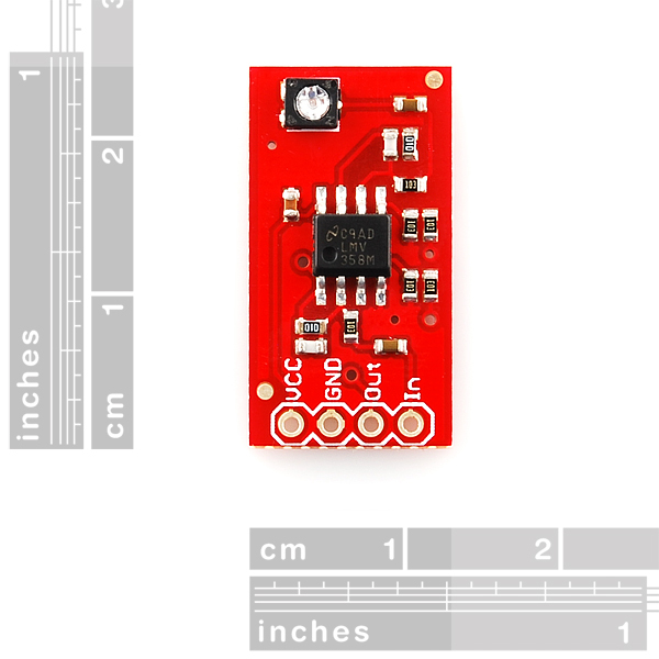
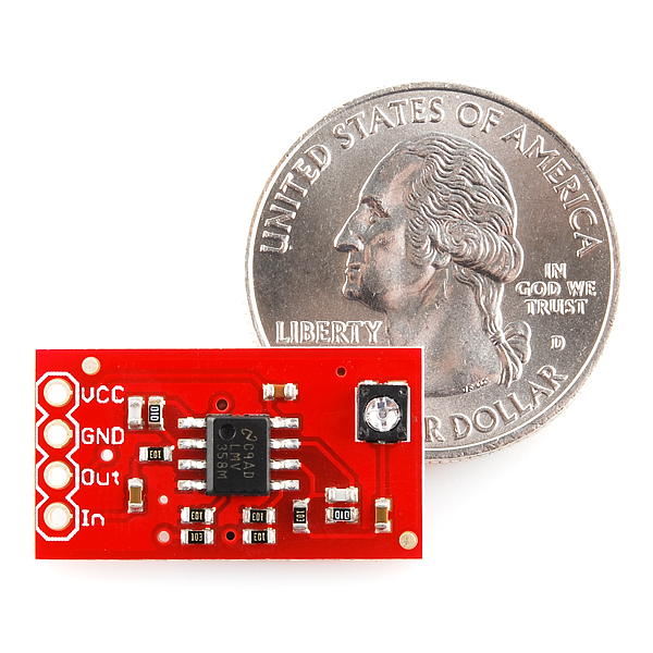
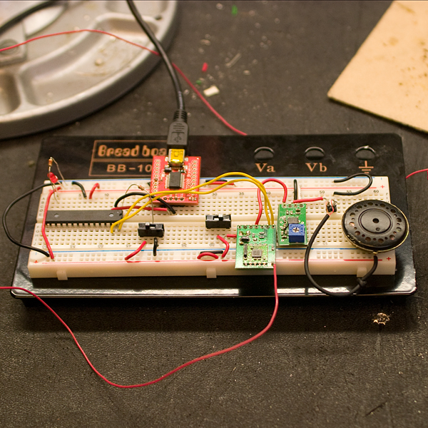
Looking at the image with the quarter & the schematic, C1 is the white one next to the VCC and GND text. C3 is the white one in the bottom right quadrant (near pin5, connected to pin6). C5 is brownish-orange in the bottom left quadrant, attached to the IN pin (remove and short out the pads if you need to pass a DC signal). C6 is brownish-orange in the bottom right quadrant, attached to the potentiometer (again, short if you need to transfer DC from op amp A to op amp B). The cap in the upper middle above pin8 is C2, used for decoupling (no need to remove).
To Sparkfun: you guys are already paying to silkscreen both sides of the boards... it wouldn't hurt to include reference designators as well, especially on boards meant for prototyping.
Amazing Le Samourai, thank you SO much.
I have some Li-Cor 210 light sensors (current producing) wired over a 604 Ohm resistor(to get a voltage). I am then using a NI-6008 DAQ to get the voltage signal into my computer. But the max voltage is very small, about 0.001 V, and thus the NI-6008 is not accurate enough. I ordered a few of these and hooked the sensor ground to the GND, the sensor positive coming from the resistor to In, and put a 5V potential on VCC. The problem is now no matter the light source, I only get a 2.5 V signal out of the Out. I have also tried all trim pot locations to no avail. Is this fixable or is the board only for AC circuits? Thanks and I appreciate any advice.
It's primarily designed for AC. But if you jump across C5 and C6 with a little bit of solder and turn the pot all the way up, it should give you something approximating meaningful at the output. My only concern would be the tolerances of the reference resistors (R8, R3, R9 and R6) and how that will propagate to the output. But if you're willing to calibrate it even loosely, I'd say you have a better than average chance of success.
Thanks Pete-O! Quick follow up question. I'm not sure how to read the circuit diagram but what I can deduce is there are three capacitors on this breakout. I think C5 is the one on the left hand side connected to In, but I'm not sure which is C6. Is it the one on the bottom right or top center? These orientations assume you are holding the board so you can read the labels on the in/out put terminals. Thanks again!
Correct on C5. C6 is bottom right, which is the one that's attached to the tap on the pot.
I tried putting some solder on the two capacitors and while it was quite difficult (I'm not so experienced with a soldering iron) I managed to do so. I also turned the trim pot all the way up (I tried both directions). However, when spun all the way to the right I get 5.05 V on the output (with happens to be the input voltage so I am concerned I short circuited the board electronics somehow) and when it's all the way to the left I get 0.5 V but it doesn't change regardless of the sensor output. Any further suggestions would be great, else I will look for an alternative route on this project. Thanks again for all your advice!
Remember that anything you have on the input will get amplified by 100 by the time it gets to the output. More importantly, it's deviation from the reference voltage of 2.5V that's getting amplified. For example, if your input is 2.4VDC, the output at the first stage will be the 2.5V reference minus (inverting amplifier) 10x(2.5-2.4), or 1.5VDC, and the output of the second stage will be 2.5V plus (inverts again) 10x(2.5-1.5), or 12.5V. Which it can't do because the supply voltage isn't that high, so it's railed (hard up against the supply voltage).
Amplifying DC is tricky. Any offset that you haven't planned for is going to jack you up. It can be calibrated out, but maybe that board isn't what you need. Hmm... Interesting product idea, though.
Pete-O, thanks for all your assistance! The explanations were very thorough. DC voltage amplification seems like a common problem to me though, do practitioners typically just build small circuits then to accomplish this? I would think there would be a board just like this one but for DC voltage, do you know of any products like that? From Sparkfun or others?
Sorry for the late reply. Do I know of any? No. I've got some ideas for how to make one, but every user would have to calibrate the thing for their own purposes. Maybe that's OK, though? We try so hard o make things simple, and I'm not sure I can simplify this one without adding a uC and somehow self-referencing the circuit. Otherwise you'd need a tritmpot on each reference to each stage. And that's fine for people that know what they're doing, but difficult to make easy for noobs. Maye we'll try, though.
Anyone had any luck using one of these to amplify an audio signal? Or using 2 in line for distortion??
Currently have a piezo running through a pre-amp into this opamp but something's not right.. How should this be powered? Stumpd.
You can definitely use it for audio, and you may not need to cascade two of these boards for any distortion. The board has 2 stages that run a gain of 10 each, so voltage gain is 100 when the trim pot is turned all the way up. Also there's no regulator on the board, so you need to run it at a voltage that's compliant with the LMV358 (2.7V-5V). Lastly, if you want to drive a speaker directly, you need to put a cap between the output of the board and your speaker, otherwise you're going to run a DC current through your speaker. No good. There's already a cap on the input, so you don't need to worry about DC there.
You'll need to short out caps c5/c6 as those make this circuit a differentiator. In other works, it blocks very low freq signals including DC.
Can you clarify which ones are c5&c6. Just want to make sure I have it right. Thanks.
This is where having Eagle installed (even if it's just the free version) can really help :)
They're two of the brown (usually!) little components. C5 is the one near the IN pin. C6 is the one near the trim pot.
imgur.com/dKupT7V
To clarify, C6 is the one at the corner of the board, near the trim pot.
thanks for the quick reply. Just installed fritzing. In the regret of sounding ignorant . . . I took them off and soldered the connection - when I hooked it up to my load cell I just get a constant 1023.
Hi . Recently I purchase this op amp and I was trying to connect this to a 3 wire load sensor 50kg. Any expert willing to give me some guidance on how should I connecy to a load sensor? Plsssssss
I'm trying to use this opamp in conjunction with a simple 3-wire load sensor sourced from a bathroom scale. When I connect the opamp and load sensor to a common 5vDC supply and ground and measure the output voltage from the opamp, I'm reading a constant ~2.7v and it will only occasionally fluctuate with weight applied to the sensor. I've tried adjusting the onboard trimpot as well with no prevail. Any ideas on what the issue could be? I've tried two different opamps and load sensors as well with the same results. Any insight would be appreciated.
I think I am running into the same thing. The schematic shows a capacitor on the input and between the stages. So this board is ac coupled. when you press down on the load sensor the output changes relative to the change of the input. But when the input is a DC, the output stays at ~2.5v , or half the VCC.
I'm wanting to use an op amp to increase the sensitivity of an ACS712 hall effect current sensor. The one I have is rated for 20 amps but I just want to measure a couple hundre milliamps and get a good resolution into arduino. The data sheet for the ACS712 shows an example with an op amp to increase the gain of the mV/A output. I think the AC coupled inputs of this OPAmp breakout are getting in the way.
OF course I am just learning so could be completely mistaken :)
I'm trying to amplify the voltage of a thermocouple (about 3mV range) and feed it into an Arduino analog input. The gain is not ideal but at least it's a starting point. However, just like the rest of you, no matter what I do, the output of this opamp pretty much stays at 2.5V, which reads around 542 on the Ardunio. At 3mV x100, the output should not be anywhere near 2.5V, more like 300mV.
I've put a pot on the Arduino input and it does range between 0-1023, so it's not the Ardunio or the code. So, this product is not ideal for these types of applications.
I suggest You use MAX6675 ( up to 1020'c ) or MAX6674 ( up to 125'c or so ... )
You are right, this will not work. What you need is an instrumentation op amp: http://en.wikipedia.org/wiki/Instrumentation_amplifier
Unfortunately Sparkfun does not sell one.
But a TI INA128 or 129 should do the trick.
Can anyone advise whether this breakout could be easily modified to create a DC amplifier with adjustable gain near 1X (ie .5 to 1.5 x) and adjustable offset? I am uncertain if the size of the board permits easy replacing of resistors or shorting of capacitors.
I have a similar question too. Can the board be modified to work in a DC application by shorting c5 and c6. A 100x net gain works for my application which is half bridge strain gauge signal amplificication. Thanks!
Yeah, then turn the pot all the way up. That should work. But I foresee you having offset problems, so you might have to adjust one or both of the reference dividers (R3 and R8, R6 and R9) to get an output in the linear region.
Could you explain to me what the voltage dividers are for on the non-inverting inputs? I just run mine to ground, but then again they're usually single stage. Also, are those 1uF caps on the inputs for noise, decoupling etc...? Thanks in advance! I would really like to go beyond my text book op-amp circuits and develop more refined circuitry like this.
These opamps are in an inverting configuration. Look at IC1A in the schematic. There is an input branch (C5 + R2) and feedback branch (C1 // R1). Think of these 2 branches as a teeter totter with the opamp's - input as the fulcrum. You can do the analysis to confirm this analogy works. In any case, when the input is above the - input, the output of the opamp will be below the - input and vice-versa. The problem arises that the power supplies for this breakout board are defined to be VCC and GND. There is no negative voltage. This is a common situation in a digital world; there is often only +V and GND. Thus, for this circuit to work properly, the - input has to be kept somewhat above GND to give the teeter totter some room to operate. That is why the voltage dividers are on the + inputs; this raises the - input (opamp will try to set its output to bring the - input to the same voltage as the + input) up to the reference + input. It turns out for general applications, 1/2 VCC is a pretty good place to put the fulcrum as the teeter totter can swing in both directions.
The 1uF caps on the inputs AC couple (or remove the DC from) the inputs. This allows the teeter totter fulcrum to be reset nicely for each stage. Otherwise, any DC difference between the input signal and the reference being applied at the + input will be amplified.
Could I use this as a headphone amplifier?
Hey Gang, I acquired a few EKG electrodes from a recent visit to the ER (ummm...don't wanna talk about it). Could I use this op amp to make a simple heart rate monitor using those electrodes?? And then send the signal to an analog input of an Arduino or MSP430?? I guess my real question is: What kinds of projects is this op amp best suited for?
Thanks!
Would this amplify an audio signal without adding a lot of distortion? Has anyone tried it out as an audio amp?
Can this breakout board be used for amplifying and sampling an electret microphone?
I've tried it and I am getting no meaningful results, just a flat line
Are you providing power to the microphone?
How do I power the electret? I am using a small 3mm electret with only a "+" and a "-". Is this right: vcc = 3v+ Gnd = electret gnd "-", output gnd "-" and power gnd "-" In = Electret "+" Out = Output "+"
Just getting hiss noise like the line is amplified but no microphone inputs coming through.
Take a look at the schematic for our Electret Breakout Board, it should give you some clues as to how to power the microphone.
Does anybody know if this would be suitable to use on the flexiforce sensor. I have looked at the data sheet and it recommends a MCP6004 op amp.
There are some issues with this circuit. How can the pot in this circuit adjust the DC level at the input of the second stage? The stages are AC coupled, not DC coupled. The input is also AC coupled, so what is the low cutoff bandwidth?
R7 acts as a volume control feeding the 2nd stage. Though I must say it's placement in the circuit is not ideal. IC1A could be overloading and adjusting R7 to a low setting wouldn't resolve that clipping problem. R7 should have been placed right at the input, before C5, then connect C6 directly to output of 1st stage.
according to the datasheet the LMV358 can only source 60am. it will sink 160ma