- Home
- Product Categories
- Serial/UART
- SparkFun Transceiver Breakout - RS-485

SparkFun Transceiver Breakout - RS-485
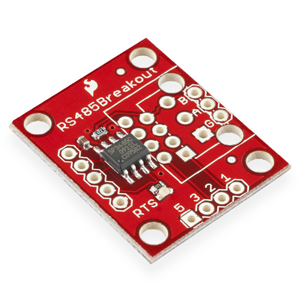
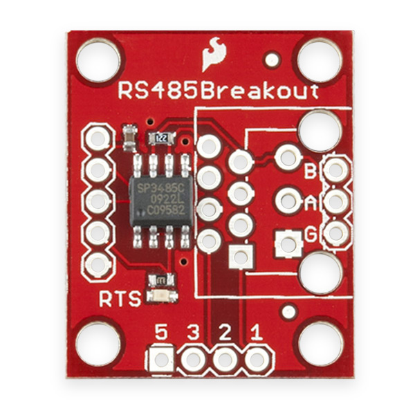
This is a breakout board for the SP3485 RS-485 transceiver IC, which will convert a UART serial stream to RS-485. The SP3485 is a half-duplex transceiver, so it can only communicate one way at a time, but it can reach transmission speeds of up to 10Mbps. This board requires a very low amount of power and can operate from a single +3.3VDC supply.
This breakout board includes the SP3485 RS-485 transceiver, filter capacitor, and other components shown on the schematic. We've broken out the RS-485 output to three different connections: (1) an RJ-45 connector, (2) a 3-pin 3.55mm screw terminal, and (3) a 3-pin 0.1" pitch header; none of these output connectors come populated.
- Fully equipped with SP3485 RS-485 transceiver and supporting components
- Operates from a single +3.3V supply
- Interoperable with +5.0V logic
- RS-485 input/output broken out to RJ-45 connector, 3.5mm screw terminal, and 0.1" pitch header
- Driver/Receiver Enable connected to RTS line
- -7V to +12V Common-Mode Input Voltage Range
- Allows up to 32 transceivers on the serial bus
- Driver Output Short-Circuit Protection
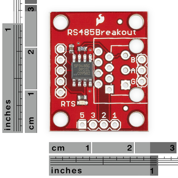
- 0.9x1.0"
- Schematic
- Eagle Files
- Datasheet (SP3485)
- GitHub (Design Files)
SparkFun Transceiver Breakout - RS-485 Product Help and Resources
AST-CAN485 Hookup Guide
March 1, 2018
The AST CAN485 is a miniature Arduino in the compact form factor of the ProMini. In addition to all the usual features it has on-board CAN and RS485 ports enabling quick and easy interfacing to a multitude of industrial devices.
2 of 2 found this helpful:
TX vs. RX:
The SparkFun Transceiver Breakout - RS-485 ships configured so that are in receive only mode until you pull the RTS pin high. When RTS is high, they go into transmit mode and will return to receive mode once RTS is low again. While in transmit mode, the board will not be able to receive any data from the RS-485 bus.
Core Skill: Soldering
This skill defines how difficult the soldering is on a particular product. It might be a couple simple solder joints, or require special reflow tools.
Skill Level: Rookie - The number of pins increases, and you will have to determine polarity of components and some of the components might be a bit trickier or close together. You might need solder wick or flux.
See all skill levels
Core Skill: Electrical Prototyping
If it requires power, you need to know how much, what all the pins do, and how to hook it up. You may need to reference datasheets, schematics, and know the ins and outs of electronics.
Skill Level: Rookie - You may be required to know a bit more about the component, such as orientation, or how to hook it up, in addition to power requirements. You will need to understand polarized components.
See all skill levels
Comments
Looking for answers to technical questions?
We welcome your comments and suggestions below. However, if you are looking for solutions to technical questions please see our Technical Assistance page.
Customer Reviews
4 out of 5
Based on 7 ratings:
1 of 1 found this helpful:
Great little board
Used this board to prototype a DMX/RDM interface for a lighting product. Work's like a charm! Just needs some screw terminals or header pins (all sold separately) to get up and running.
1 of 1 found this helpful:
Would be 5 stars with a simple connection diagram
There are so many unneeded pins here that it makes it a little confusing what you really need.
Just a simple drawing showing it connected to an arduino would have served me some time. In the end I just swapped pins till it worked.
But when it worked it was super simple.
I’m still not sure if it’s one directional though.
5 of 11 found this helpful:
PROCEED WITH CAUTION
Although it is reasonably priced and possessed of a clever variety of plated holes for the attachment of various connectors, if I had done my homework I would not have purchased this board. Why? Because the obscure SP3485 chip that it uses does not have automatic flow control and is therefore not compatible with many popular open source libraries for RS485 and in particular Modbus RTU.
Unfortunately there don't seem to be a lot of other choices except certain parts in online auctions and building one's own board with MAX488, MAX13487E or another flow-control transceiver.
So this board delivers what it promises, but what it promises is a clever implementation of a chip that no one else uses for quite good reasons. Not recommended.
Handy little breakout.
Worked fine in my application. I needed to replace the C grade part with an E grade part for wider temperature range. The C grade part will be fine for most applications. It was nice to be able to simply swap out the part.
0 of 3 found this helpful:
Extremely Poor Documentation
I should not have to load up Eagle to get a correct schematic and layout of the board. The Schematic file should be complete
You are looking at a PDF of the Eagle schematic. It is not incomplete, it simply makes use of hidden connections that are managed within Eagle. The easiest way to view the traces is in Eagle. We post the PDF and the Eagle files so that the end user has the option to view as either. However, for best experience, using Eagle to view the schematic allows quicker and simpler navigation through the wiring.
-------------------- Tech Support Tips/Troubleshooting/Common Issues --------------------
Example Hookup and Arduino Code
Try looking at this article to for a general connection using the RS485 protocol [ https://arduino-info.wikispaces.com/RS485-Modules ] and some Arduino Example code [ https://arduino-info.wikispaces.com/SoftwareSerialRS485Example ].
That has to be one of the most useless videos I've seen in a while. How many times are you going to say, "My guess is..."?
Hi everyone! I am confused about the 220Ohm -so called terminator- resistors as it is recommended to use a 120 Ohm resistor near to each node, is it the same resistor in the RS-485 line or is recommended by the IC Manufacturer? even though it is not mentioned in the datasheet of the IC. BTW , if I want to use this module with some Biasing and EMC protection(I have already lost one module and the Arduino board connected to the module) , how should I consider this resistor because all of the documents are general and based on 120 Ohm P.S. I am trying to send some data with low baud rate on an about 10-20 meter CAT6 cable.
Lots of Good Stuff about using RS-485 beyond the lab bench at...
http://store.chipkin.com/articles/rs485-rs485-cables-why-you-need-3-wires-for-2-two-wire-rs485
The schematic says that there is a 220 Ohm termination resistance between A and B. But when I look at the picture of the board it shows that there is actually a 1.2 kOhm resistor present. Is there any specific reason for this? As normally for RS485 a 120 Ohm termination resistance is used?
Not sure about the one in the picture, but the build list for this board has a 220 ohm resistor in it and no 1.2K resistors. Rest assured the product we actually ship has a 220 ohm resistor.
I have just bought this board and although it does what is says it uses 20mA?
I have the board connected to a 3.3V regulated power source as well as the RST line to hard wire to transmit mode. This appears to draw 20mA? Is that what counts as low power or I am I doing something stupid here?
Thanks in advance for any help.
The bus has a 200 ohm termination resistor so at 3.3v it will draw 16mA, so that seems about right. That's not the driver's fault.
I have two of these wired up to UARTs 4 & 5 on a Beaglebone Black. The UARTs are properly (and tested!) muxed in the overlay. So I have TXD, RXD and RTS connected to the equivalent pins on the BOB-10124's (TX-O, RX-I and RTS pins) along with the requisite +3.3V and GND.
The BOB-10124's are connected with about a foot of CAT5 cable, A-A, B-B and GND to GND. My application code is pretty simple.
For both UARTs, I open /dev/ttyO4/5 and set up the speed etc. (no RTS/CTS):
UART4: Simply reads from the UART, prints out what it gets
UART5: 1) RTS enabled with ioctl(TIOCMBIS) on bit TIOCM_RTS 2) Delay 25ms 3) Write message 4) Delay 100ms 5) RTS disabled with ioctl(TIOCMBIC) on bit TIOCM_RTS
However, I cannot get it to transfer anything (or at least the receiving module (UART4) doesn't receive anything). I do see the RTS LED go on, then off after a brief pause, so it looks like it's sending. I know the pins and UART config is correct because if I just cross the UART pins directly it works fine.
I've tried many combinations, enabling RTS/CTS in the ioctl(TCSETS) initial set up ... so far nothing has worked.
I have a Saleae Logic, but it's an old one and doesn't do RS-485 (it's limited to 0-5v and doesn't have any analog channels), maybe this is an excuse to buy a Logic-8 ...
Any thoughts?
Figured it out ... The UART TXD should actually go to RX-I and UART RXD to TX-O. Seems odd that this should be the case, but now that comment somewhere below about the TX-O/RX-I pins being swapped on the SP3485 makes sense ... Hope this helps someone.
Any chance of starting a repo for this product? We've made an improved version of this board now which doesn't require the RTS pin. The change makes use of the Max13487 chip which has a built in state machine to determine the Rx and Tx directions. No more struggling with getting the timing delays correct for the RTS triggering. We use the new board design to communicate reliably with industrial equipment such as HMIs and VSDs at anything up to 115200baud. We'd love to share the changes with you, but don't want to start our own repo as it would be better placed under your original design. Thanks in advance...
I just ordered a Max13487. I would love to see what you have done!
Could you share your design? I am interested in a breakout board for the max13487 and the changes you made.
I know its been a while but, for anyone else wondering about the Max13487 you can pretty much drop it into this board's design no problems. I fried the original chip and was able to replace it with the Max without any issues or code changes. I believe that the Max's datasheet calls for pull-up and down resistors on the A&B lines but I've had no problems without them so far (I'm probably missing something important but, meh, it works.).
I am interested in the new board design using the Max13487. Will Sparkfun be carrying these soon? If not does anyone know where I can find one or find the design and parts? I've been messing around with the 485 breakout board now for about a month and it is extremely difficult to get reliable fast communication. At best so far I'm only able to get communication speed to about 1/3 as fast as it should be and I still have some errors. When I use a USB to 485 it works flawlessly, except I don't want to use USB for the finished product.
So, I'm new to RJ485 and, if I use this board, I will be using this board for all the nodes in my little network so I don't care if it is compatible with other boards and I don't care if it is full-duplex. What I need to understand is how to connect them all together and communicate.
There is a Network Topology diagram at the bottom of this page that makes it look like it is as simple as connecting all the R's and S's on a sort of 2-wire bus with a couple of resistors at the ends. The wikipedia page for RS-485 describes several different topologies. Master-Slave would suit my project the best (but isn't an absolute requirement), but then I read on this other page that master-slave requires 4 wires and full-duplex.
Regarding communication, is it just as simple as connecting them to the TX/RX of the UART on my Raspberry Pi and Arduino boards? What about voltage translation between 3.3v and 5v devices? I know they boards can handle both but will the network of them handle a mix of voltages coming from the devices?
So, can anyone help me sort this out. I don't want to buy the boards until I at least have a basic understanding of how to use them.
Messing around with RS-485 a couple years ago, the TI Design Guide helped me the most to figure things out.
RTFM! I admit it was me being stupid, but it doesn't help that they've named the pins differently from the chip. I really didn't expect the breakout labeled "TX-O" to be connected to "Pin 1 – RO – Receiver Output".
Hi, could some one please help me with connecting this adapter to an arduino (pro micro 5V 16 MHz). Any help would be appreciated. Thanks
The SP3485 specifies the Vcc to be 3.3 V. Is it allowed to operate this component with a Vcc of 3.0 V.? There is no indication whether this is allowed or not.
I got a few of these for prototyping a home automation project, connecting a bunch of stuff over CAT-5 and RS-485. I notice that the blue pair (4&5) are connected to ground in the schematic of the breakout board, but PoE (on wikipedia anyway) says the blue pair are DC+ and the brown pair DC-.
Is the breakout board wired for a different standard, and if so, which one?
would this be a practical solution to increase the length of spi lines. i only need output. my theorey wa to place one of these on either side like so:
arduino -> spi -> rs485 -> [long cable run 100ft] -> rs485 -> spi -> ws2801
or something similar. is there a better solution?
thanks!
-matt
can someone tell me where can I find this in the Sparkfun Eagle libraries ???
Help please... Can someone please provide a schema on how to connect this boars?? I have in one side a device with RS485 that is sending out data (I just send out and I don't need to read) and I would like to connect few of this board and get a TTL out from them? I try few times but without good result... Thanks
I've been using this breakout for about a year now and it's been working pretty well. I've noticed from the beginning, that I need to have a delay of about 25 ms after I send serial data before I can bring the RTS line low otherwise the transmission gets corrupted or is not transmitted. This hasn't been a big issue yet, but for a recent project I am running two 485 lines from one Arduino Mega 2560. I am receiving commands on one 485 line from the host software and transmitting them if the address is correct (I have several Megas running). I am expecting a response on the second 485 line from the devices I am sending commands to. The issue is that the peripheral devices respond in ~20ms and sometimes I get it and sometimes I don't (based on the state of the RTS pin). I need to transmit these responses back to the host software.
I feel like I should need these delays in the program. I would assume that the arduino has completed the transmission before it moves on from a serial.write() command. Any ideas?
This is an interesting issue when designing half-duplex systems: when you're done transmitting you need to quickly switch to receive, but because the UART buffers at least one character (it will return to your code when it starts, not finishes, sending the last character), how do you know when you're actually done transmitting? I don't know exactly how the Arduino Serial driver works, but it might be worth digging into the source code (yay open source!) to determine if and how it is buffering characters before sending them. You might also look at the 2560 datasheet, as there is likely a UART status bit that is asserted when the UART is busy transmitting, which is something you could busy-wait on to deassert RTS immediately after the last bit is sent. With the above knowledge, you might be able to tighten things up in your code, or even hack on the Serial driver to automatically assert RTS while you're sending data and deassert it when you're done.
Arduino is great at making the easy stuff easy. Here you're pushing it into something new, which may take a bit of work, but the nice thing about open source is that they give you the freedom to do so. Good luck and let the world know your solution to make it easier for the next person who wants to do this!
Hi Mike, just a quick follow up on this. We played with this breakout board, as well as the Max485 for a few weeks. It is extremely sensitive to delays and timing in order to trigger the RTS line reliably. We decided instead to use the Max13487 chip which has a built-in state machine and handles the TX-RX latching by itself. This removes all of the delays from the Modbus library file and also frees up the RTS pin. We now have Modbus running flawlessly at 115200baud. This is only positive criticism, but I would highly recommend and suggest that you change your Modbus chips to the Max13487. I think the majority of us customers would rather just plug and play and the sadistic ones can buy their own Max485 with an RTS pin and spend weeks debugging :) Use it, don't use it...
What code are you using to drive the Max485? I've been working on a project where I've used both Max485 and ST485's directly (no breakout board) and haven't seen this problem, I can reliably get no-op responses from a remote board in ~1ms, however I've only been doing using SoftwareSerial and not the built in serial. I've also been using direct communication and not-DMX, using http://www.gammon.com.au/forum/?id=11428 (worth checking out, depending on what you're doing with it) combined with a socket-like layer I've been working on (https://github.com/aphelps/HTML/tree/master/Libraries/RS485Utils)
Will this help? http://pydoc.org/2.5.1/termios.html "tcdrain(...) tcdrain(fd) -> None Wait until all output written to file descriptor fd has been transmitted."
serial.flush() may help
if the delay seems excessive make sure you have 220 ohm termination at both ends of the twisted pair
am trying to connect Sparkfun RS485 breakout to Xbee Pro modem. Since the RS485 breakout uses the SP3485 RS-485 transceiver IC which has its RTS pin to control the data flow I assumed that this signal should be obtained from the Xbee RTS (DIO6), or CTS (DIO7). Although both IOs where configured as RTS and CTS respectively, they fail to show any change in their status when data sent (from PC) or received from another Xbee..
Has any one tried this type of connection ? and can offer advise with tat regard.
The issue you're running into is that RS-485 is half-duplex (it can transmit or receive, but not at the same time), while the XBee is full-duplex (separate transmit and receive lines).
What you'd need to implement this is a signal that indicates when you're transmitting and when you're receiving. Unfortunately RTS and CTS don't provide this signal. They're for flow control, which allows the two sides to tell each other if their buffers are full and data transfer should pause to avoid losing data. I don't know of a signal on an XBee that could be used for this. You might be able to approximate this signal from your host system, but you'd need to be sure to switch to receive immediately after sending your data to avoid losing any of the reply, AND you'd have to reliably get this signal to both ends of the RS485 bus, which kind of defeats the point.
I can think of two ways around this problem. One is to use a total of four RS485 boards, two for the TX and two for the RX signal, with the direction control permanently on. This would give you a four-wire connection with all the benefits of RS485. Another option is to use RS422 instead of RS485; RS422 is the full-duplex version of RS485 (there is no direction control). SFE doesn't currently carry any RS422 hardware, but the chips are out there and very easy to use.
Anyone have any other ideas? I hope this helps, good luck with your project!
Stray solder balls? Sure I can clean them up with my soldering iron, but for this price we should get some sort of quality control.
Has anyone had any luck using this with an arduino? I'm trying to drive a dmx light using the tinker.it DmxSimple library.
How do I know what uart baud rate to use when connecting to the tranceiver.
The rs485 side is connected to a "black box"
This board doesn't care what baud rate you use, it just passes the signal straight through.
But if you don't know what baud rate your black box is using, you'll likely have to try all the standard values to see if it responds to any commands.
HI,
I know this might be stupid, but is there an easy way to connect this to a usb to rs232 converter on the UART side?
Thanks
If you ultimately want it to end up in a USB port, an FTDI Basic Breakout would be an easy way to do so.
I considered using this breakout for my projects but the lack of full duplex capabilities had me looking elsewhere. I settled on the max488. A breakout of that chip would be very awesome. Of course the downside is that the max 488 is limited to 250 Kbps but I only needed it for serial translation from ucontroller to ucontroller.
Why does one need a breakout board for a part which is available in thru-hole packaging?
to monitor the 485 bus while transmitting (for collision detection), would it work to separate pin 2,3 on the sp3485 and then ground pin 2? That would still leave transmitter control on the RTS, but would it then receive while it was sending?
There should be an assembled picture of this. In my haste to order I didn't realize the break-out was either RJ-45 -OR- 3.5mm screw terminal. The verbiage states "and" not "or".
Upon receiving it, I realized that the side-pins are the standard .1" header pins mentioned, not for the screw terminal which only mounts if you do not mount the RJ-45 connector.
It's my fault for not doing enough looking at the schematic/eagle board layout/PCB picture, but a simple picture of the completed PCB would have helped.
In addition to my previous comments, I have found another flaw. There are no provisions for pull-up/pull-down resistors. The A/B RS-485 lines don't make their way to the breadboard so you can't put pull-up/pull-down resistors on easily.
Also, why a 220 ohm terminating resistor? If you're using Cat-5 isn't the impedance of the twisted pair typically 120 ohm?
Assuming you use one board at each end, the two 220 ohm parallel to 110 ohm, and you're correctly terminated.
Hello everyone, i wish you could help me...
I bought this module a while ago and i was trying to make a simple application using a capacitive keyboard that sends data using RS485 protocol and my new Arduino Mega.
The thing that is going on is that i am able to send messages to my keyboard from my arduino, but not in the other way... the arduino code get stucked in the line where the serial is supposed to receiva data.
It is possible that the receiver module of the SP3485 chip is not working properly? or what else could it be?
Greetings,
I could use this in my next DMX-512 design.
Any chance for a full duplex transceiver? Possible even a breakout with optical isolation, protection circuitry, and a DC to DC converter for isolated power?
i noticed that full duplex could be possible by connecting a second board's A and B pins to the pins 1, 2, 3, or 5 of the first board when using a RJ-45 connector.
but a full transceiver board with extra circuitry would be nice
I was just about to ask for the same thing
Add me to the list as well. I'd love to see a SparkFun DMX-512 board.
yea i would also really really really like a sparkfun DMX-512 transceiver board