- Home
- Product Categories
- Arduino Shields
- Mux Shield II

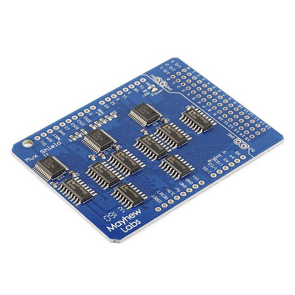
Sometimes you've got way too many inputs, or outputs... or both. How are you going to get them all connected to your Arduino? The Mux Shield, that's how. The Mux Shield II from Mayhew Labs is an upgrade on their previous Mux Shield which makes it possible to route up to 48 analog and digital inputs or digital outputs to and from your Arduino board.
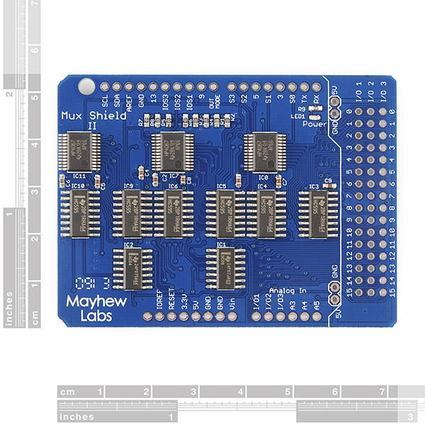
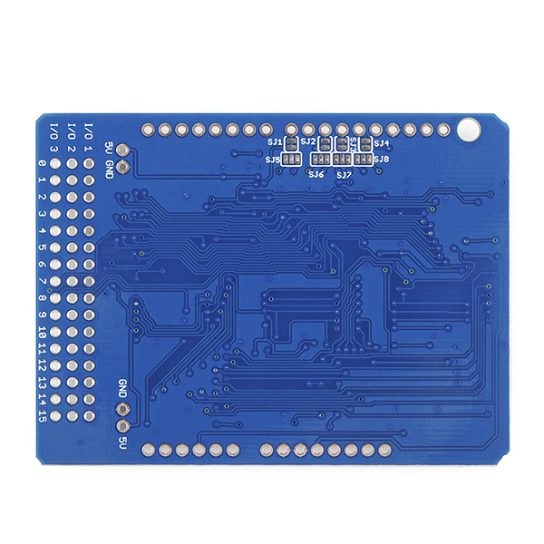
The Mux Shield II improves on the original by moving all of the I/O pins to the end of the board, thus allowing you to add one big connector and hook up a ribbon wire or similar cable solution. This also gets the pins out of the way so that the Mux Shield can be in the middle of a stack, with a shield on top of it, and you can still get to the I/O pins. The pins are arranged into three rows of sixteen and each row can be individually set as a digital input, a digital output or an analog input from the Arduino sketch! Further increasing the flexibility of the board, Mayhew Labs added solder jumpers to the bottom of the board that allow you to shut off this software control feature and "hard wire" the functionality of each row, freeing up the associated Arduino pins for other shields in the stack.
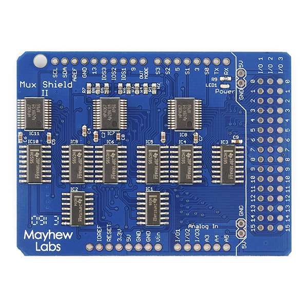
The Mux Shield uses TI 74HC4067 analog multiplexers (mux’s) for input functionality and TI 74HC595 shift registers for output functionality. Don't worry if that's jibberish to you, the included Arduino library wraps it up and makes it very easy-to-use.
The shield comes without any headers so be sure to pick up some stackable shield headers!
Replaces:DEV-09832
- Control up to 48 Pins from your Arduino!
- Multiple modes:
- Analog Input
- Digital Input
- Digital Output
- Solder Jumpers for Hard-Wired Mode Select
- Arduino Library and Example Code Available
- User Guide
- Schematic
- Datasheet (74HC4067)
- Datasheet (74HC595)
- Arduino Library
Mux Shield II Product Help and Resources
Core Skill: Soldering
This skill defines how difficult the soldering is on a particular product. It might be a couple simple solder joints, or require special reflow tools.
Skill Level: Rookie - The number of pins increases, and you will have to determine polarity of components and some of the components might be a bit trickier or close together. You might need solder wick or flux.
See all skill levels
Core Skill: Programming
If a board needs code or communicates somehow, you're going to need to know how to program or interface with it. The programming skill is all about communication and code.
Skill Level: Rookie - You will need a better fundamental understand of what code is, and how it works. You will be using beginner-level software and development tools like Arduino. You will be dealing directly with code, but numerous examples and libraries are available. Sensors or shields will communicate with serial or TTL.
See all skill levels
Core Skill: Electrical Prototyping
If it requires power, you need to know how much, what all the pins do, and how to hook it up. You may need to reference datasheets, schematics, and know the ins and outs of electronics.
Skill Level: Rookie - You may be required to know a bit more about the component, such as orientation, or how to hook it up, in addition to power requirements. You will need to understand polarized components.
See all skill levels
Comments
Looking for answers to technical questions?
We welcome your comments and suggestions below. However, if you are looking for solutions to technical questions please see our Technical Assistance page.
Customer Reviews
5 out of 5
Based on 2 ratings:
I believe you made it just for me!
I am a model railroader. My system has 16 turnouts and 23 Occupancy detectors. I have a panel with 16 toggle switches. 16 inputs from toggle switches, 16 outputs to control turnouts and 16 of 23 analog inputs from occupancy detectors! The only thing better would to have 7 more circuits. However I cut down a bit using serial shift registers for some things. Truly a wonderful addition to my electronics.
very nice board with an attractive Price. It is working very well.
Is the shield compatible with Raspberry PI 3?
I have been trying to set multiple (n>=2) outputs at once but haven't been successful. Basically: muxShield.setMode(1, DIGITAL_OUT); muxShield.digitalWriteMS(1, 0, LOW); muxShield.digitalWriteMS(1, 1, LOW); muxShield.digitalWriteMS(1, 2, LOW);
Only triggers 2 outputs. It works fine when individual PINs are addressed. Is this a limitation?
This is the first shield I have purchased that had no headers to connect it to an arduino. I expected to have to do some soldering, but I didn't expect to have to buy separate headers. I'm sure that is my own fault and I probably could have figured it out if I looked more carefully. But I'm still disappointed.
It is not at all easy to tell what this product is capable of. I don't want to switch analog inputs INTO an Arduino, I want the Arduino to control the switching of audio inputs between other external devices. Can this be made to do that? I'm looking for some kind of analog switch or crosspoint switch shield where the only connection to the Arduinio is the switching control lines. I'd like to build a box that can control independent analog ins and outs, interconnecting them programmatically using the Arduino....
The analogue has an output option, so you can use this as the switching signal to a transistor in-line with the audio signal. Don't forget to ground the unused pins, and I most certainly don't promise a lo-noise result! What on earth ar you using so many channels for? Most mixers have mutes available, so it can't be that. Switch pots are the traditional solution for teaching labs.
Are these stackable / daisy-chainable? I want to get MANY inputs into an Arduino - up to 500+. Would something like this make it possible? Or would this just be unreasonably slow (i.e. would it take forever to read all 500 inputs)?
You read my mind!! This is what I need to make my arduino controlled, web based fireworks launcher more reliable and compact... uhh.. I mean my model rocket launcher.. :-) Only 3 months to go 'till 4th of July you know!!
I doubt it. You might do better looking at the AdaFruit 16-channel servo board which is stackable (each board needs an address setting to distinguish it from the rest of the stack, done by binary shorting pins on the board).
Wouldn't it be a lot cheaper, and use less pins just to get a few shift registers? something like a 74HC595 since that is what it is using anyways? 6 of them (to get to 48 pins) would cost $9 and only use 3 pins
You're absolutely right, and that is what my "version 1" was, but even though it worked most of the time, I had some strange thing going on where occasionally, the shift registers would "go crazy" for lack of a better description, and start turning ALL of the relays on and off at complete random. Putting this board in place is my attempt to be a little more integrated, and have less of a chance for me mis-wiring a clock signal or something else dumb. I probably wouldn't care too much, because it was onlly an occasional problem, but since rocket ignition was the potential result, I didn't want to risk it... Safety first, especially since when we're launching rockets, there'll probably be some boy scouts around....
I totally agree with the safety concern, but I handled it differently. I chose to control the igniters with relays attached to my shift registers. They are controlling a 12v supply to the igniters. I installed a Key Switch in front of the common supply that runs to the igniters. The safety rule is no one approaches the tubes without the key in their pocket. That way we know there is no chance of an accidental ignition. Everyone feels safer when the machine is incapable of lighting the shells(disarmed) while the tubes are still being loaded. Even if a shift register got damaged and fired one early, no one would be near it.
Yeah.. Mine was the same.. My shift registers were connected to these relay boards:
And, I also had a disconnect for the output side.. (I was using a 9v battery for launch, and had a switch)...
it makes no sense, but SOMEHOW, the problem I had was ONLY becoming an issue when the 9v was connected...
I'm sure I had a bad connection somewhere, but it will definitely be easier to find if I simplify..
I wanted to use this multiplexer to control a few servos at a time and there was a lot of stuff on the web saying that it couldn't be done. The code below is for two servos. I've combined Adafruit Softservo with the mux shield code. If you have any improvements, please post here. Here is a video of it controlling 21 servos.
Can this be use with the arduino mega 2560 r3 and if yes how many analog ports would it have then?
Once I soldered the headers on and installed the library it was working right out of the box correctly except that all of the information it was returning was garbled. The default baud set in their examples (contained in the library zip) was 28800 and when i increased it to 38400 or 57600 it then became perfect. (arduino uno R3)
I am using it for 48 analog inputs, and you must ground all unused inputs or they will transmit meaningless data.
simply put a resistor between "I/O x" (x could be 1 ,2,3, depending on which row of pins you are working) and ground could remove all meaningless data in the empty pins.
Hi. I'm an uber-noob. Are folks familiar with the johnny-five project? A javascript firmata based Arduino framework...it's cool. I wonder if I can use this mux shield along with johnny-five? Sorry for the probably stupid question.
https://github.com/rwaldron/johnny-five
Hi
Please help resistive 7x10 matrix sensing Sample program we could share with me how to read the data matrix
I have two questions.
Does anyone know if the arduino Library works with the Mux Shield Version One.
I am having trouble running the digital example on my Leonardo. The analog example works fine but digital input does not show any change when the button is pressed. I have the Ground and I/O connected to a button. Am I missing something other then a button? I also tried to connect the 5v and I/O to the button still no change.
Can anyone tell me when to use a shift register and when to use a MUX? I think I understand how they both work. It seems to me that a MUX is faster and better for most purposes.
To simplify, use a shift register for digital, and a mux for analog.
How much current can each output support?
I'm in a position where I need just a few more inputs. I'm building a midi xylophone and I want at least 4 octaves, which would use all 48 inputs, but I need some control components as well (octave shift, modulation, etc). Is there any alternative to this that I can use, or something I can add to this?
You can still get more I/Os from an Arduino mega, but I guess they're not ALL analog...
Worth to mention The Mux Shield uses Arduino digital pins 2, 4, 6, 7, analog input pins A0, A1, A2, and optionally uses digital pins 8, 10, 11, 12.
We've all blown a pin on our Arduino through bad soldering, misplaced wires, forgetting a resistor, or something of the sort. When that happens on this shield, do multiple pins "die"? Additionally, can I attach this to my Arduino that has lost a pin, and get more pins back? How many pins will be useless if my Arduino is one pin short?
This will compact my DCPU-16-on-Arduino w/30-pin RAM down from a Mega to a regular Uno or Leonardo. Nice!
All CMOS devices are type HC, not HCT, so 3.3V control signals would be near the minimum spec value for recognition as a logic "1". It would probably work, but temperature and unit-unit variations could cause mysterious errors over a population.