- Home
- Product Categories
- Wireless and IoT
- Bluetooth SMD Module - Rayson BTM-182

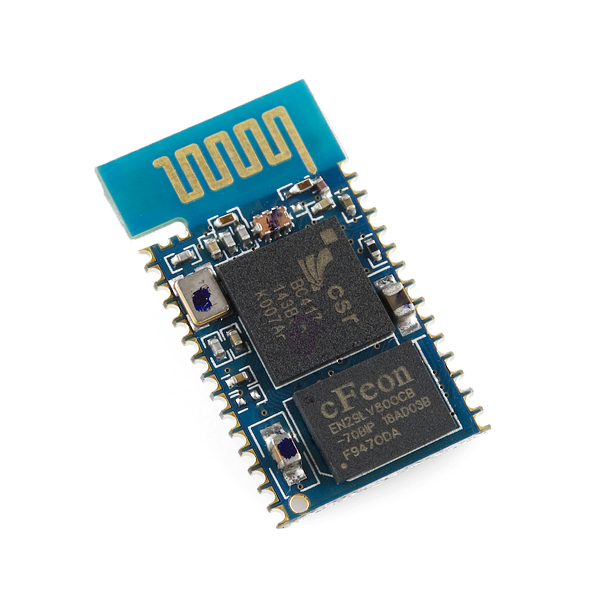
Bluetooth SMD Module - Rayson BTM-182
Replacement:WRL-10253. While there is no direct replacement for this part, the RN-42 is a similar module and a suitable substitute in most applications. This page is for reference only.
This module is the Rayson BTM-182. It is an easy to use Bluetooth SPP (Serial Port Protocol) module, designed for transparent wireless serial connection setup. This is a fully qualified Bluetooth V2.0+EDR (Enhanced Data Rate) 3Mbps modulation with complete 2.4GHz radio transceiver. It uses CSR Bluecore 04 external single chip Bluetooth system with CMOS technology and with AFH (Adaptive Frequency Hopping).
The firmware for the BTM-182 is the same as for the BTM-112.
- Class 2 module with PCB antenna
- SPP firmware
- Bluetooth standard Ver. 2.0 + EDR compliant.
- Low current consumption
- Hold, Sniff, Park, Deep sleep modes
- 3.0V or 1.8V operation
- Support for up to seven slaves : SCO links <3>, ACL links, Piconet <7>
- Interface: USB, UART, and PCM (requires voice CODEC)
- Support for 802.11 co-existence
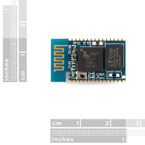
- 25.0 x 14.5 x 2.2 mm
- Module Datasheet
- [Command Set](http://www.sparkfun.com/datasheets/Wireless/Bluetooth/SPP AT command set.pdf)
- BTM-112 Datasheet for reference only
Comments
Looking for answers to technical questions?
We welcome your comments and suggestions below. However, if you are looking for solutions to technical questions please see our Technical Assistance page.
Customer Reviews
No reviews yet.
Im glad yall are selling these now. Beats the heck out of 60$ bluetooth modules. I do smell a breakout board coming for these tho.
Hi,
Your nose doesn't lie. That is the smell of fresh breakouts. A Breakout board is in the works.
Thanks,
Tim
Is there any information about the release of this breakout board?
I have no idea what the normal timeline is for this kind of boards, so don't feel pressurized about this question.
Thanks anyway.
We are in the final stages right now but ran into an issue with cleaning. You guys will be the first to be able to purchase them when they are for sale ;-)
Hi everyone,
Does someone have working code for BTM-182? Command set document is very poor.
Thanks.
Darko
I have been having many problems trying to get this module to configure. I have the following setup:
Computer -> Xbee ~~~~~~ Xbee -> MCU -> BTM-182 ~~~~~~ Computer
I have been using the bluetooth on the computer to talk to the module, and If I run different commands such as: "+++" then "ATL3" followed by a CR and it returns OK or ERR every other time. If I send the same command again, while it is still in command mode, it could say ERR when just before it said OK. Everytime I send a command to ask for it to return things, "+++" then "ATI?" followed by a CR, it never returns things. I am able to connect to it from computer, and I am able to connect to it from the MCU. I have the MCU setup to echo anything it receives via xbee to bluetooth, and visa versa.
Can you configure the bluetooth module through the bluetooth connection, or is that something you can only do via the direct Uart connection?
Thanks for your help :-)
Edit Found out what was wrong, which was multiple things:
1. '+++' When I sent a '+++' from my usb xbee adapter, remote xbee would enter command mode. I tried to get around that by having arduino send the '+++', but it was echo'd back from bluetooth and all of the bluetooth responses were sent back via xbee, which put an xbee in command mode. Solution only echo back non + characters.
2. Problem was that the bluetooth responses were looking garbled. The problem was that I was using a read_byte function who's timeout was configured to be too high. A 1 ms timeout is sufficient to capture the data at 19200 baud.
Problems solved, glad I stocked up on these modules while they were in.
I guess i should post this here... i have been getting complaints about this not letting you use :
921.6Kbps
as the baud rate. So i decided to try it out and see. I can set the baud using ATLx... its default is L2 which is 19200bps but when i try L8 which is 921.6Kbps i get ERROR returned. I though heh maybe im typing it wrong so i tried L7 and it works fine!
So i assume that baud rate isnt implemented in this firmware?
How to enable deep sleep or other power saving modes? Can't see anything about it in the AT commands... Thanks, Alex
I am trying to connect the module to a simple Serial TX/RX (ftdi 232 chip). The power supply, TX/RX lines are all 3v. Whenever I send the commands to the chip using hyperterminal, the characters that are typed get repeated multiple times. When I try to type "AT B?" I see "AAAAAAAAAAAAATTTTTTTTTTTT BBBBBBBBBBBBBBBBBBB????????????????" and after hitting the enter key multiple times, "ERROR" is displayed multiple times. I have checked my soldering connections and there are no shorts/bridges between the contacts. Please let me know if anybody has been able to get this to work over simple serial connection. My connections are as follows : PIN15 - GND, PIN14- 3.3v, PIN 10 - UART TX(from PC) , PIN9 - UART RX(to PC).
Thanks,
Rajesh
Way to go SparkFun! You've finally realized that these modules aren't worth the $28 US you were selling them at, thus purchasing my allegiance.
Has anyone had any luck with the USB functionality?
I was curious i recently bought this item and tried to connect it to 3.0v and nothing but when i connect it to 5v it worked. also i was wondering i connected my bluetooth usb to it and connects but i cant see anything in terminal. how do i change the settings in this
Just ordered one of these thanks to freeday! :D Ill be sure update you all with some cool projects...
BTW my blog is http://atomsoft.wordpress.com
wanted to update all here:
http://atomsoft.wordpress.com/2011/02/03/bt-up-and-running/
I've used the RN-41 before, and I just found this one. I'm not seeing much of a difference between them. What are the pros and cons of using this over the RN-41 (other than cost)?
Hi, any additional infos for PCM interface?
Frequecies, Bit....
What FW is installed in? Gateway, Headset,...?
Thanks
Hi All,
Can anyone confirm for me that CSR/DSR hardware flow control is known to work on these modules? In my application, I have a very small receive buffer, so I must be able to flow off the output of the local bluetooth module so I don't overrun.
There are quite a few modules out there that look very similar, yet none of them seem to indicate that flow control is working. A lot of them reference standard schematics with flow control not used.
I'm happy to pay the extra $$ for a module that is of higher quality and known to be fully functional, as opposed to getting a module from China directly with unknown performance.
thanks.
uh. I mean CTS/RTS. too early in the AM to be thinking clearly.....
Hi,
i would like to connect this module with the standard audio i2s or S/Pdif interface for music streaming.
So, i need the data of this module area/(PCM Pins:
PCM_OUT, PCM_CLK, PCM_SYNC, PCM_IN, to connect it to a i2s IC audio digital receiver.
Hey guys just wanted to share my love for this chip. The soldering technique that worked best for me was to solder 2 resister leads to all four corners of the board and place those leads onto the .1 spaced protoboard, then solder more resister leads onto the pins I needed to access.
The AT command sheet is pretty simple, there are a couple commands that need specific modes to be in so just keep pluggin away. NewSoftSerial library works well, just do a print("ati1\r"); or similar command to submit. The longest part for me was figuring out how to communicate with it i tried ati1, ati1\n, ati1\r\n, then lastly the correct one of ati1\r. Blah blah blah, it auto connects with my android phone great, able to send strings back and forth.
My problem is that it stops auto connecting for some reason with no recurring pattern. Sometimes after 4-5 connections/disconnections, sometimes 10-15. My arduino keeps going but its not making the connections any more. Any clue why?
Hi Richard,
Could you share your software for both the board and android phone sides? Thanks! Please send it to gjdepaula at hotmail dot com.
Hi Richard,
Can you share your experience?
My wish is to display values generated by a microcontroler on an android phone.
Jean-Marc
Richard, can you share the code please or drop me an email to alkopop79 at gmail dot com? Thanks!
Greg
I didn't see a range spec for this one. Any ideas?<br />
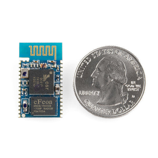
Also has anyone weighed one of these modules? <br />
I wanted to compare it to the RN-41. Anyone with weights on either of these modules? Thanks
I'm showing it as 0.0022 pounds.
Wow less than a GRAM that's awesome! No word on the range yet?
I found part of the answer to my question. This is a class 2 module which is 2.5mW power output max @ 10 meter range. http://en.wikipedia.org/wiki/Bluetooth<br />
The other module is class 1 which explains the 100 meter range with 100mW power output. It will also burn through your battery much faster.
May I know this BTM-182 is 1.8V version or 3.3V version?
These are the 3.3v versions.
Please update the product description above, it's quite confusing that is uses the (copy-paste from manufacturer's PDF, I guess) dual values. Especially since "3.0 V" isn't even true, it's 3.3 V just as you say.
The specs on this page says "3.0V or 1.8V operation" and the datasheet indicates to different version of the modules (page 1 under General Electrical Specifications). The datasheet also seem to indicate both 1.8 and a 3.3 volt supplies are needed if it should run at 1.8 volts. Could you please clarify this a bit before I turn my modules into smoke particles.
I hate to be repetitive, but any news on the breakout board? Looking to convert my Das Keyboard into a bluetooth keyboard.
Look in the related products, we have it for sale.
Can i connect this module to an AVR UART port and send AT commands via bluetooth to a mobile phone which supports serial port service and also can work as a gsm modem (sony ericsson w880i)? Or it can't make bluetooth connection between a cell phone?
You should be able to communicate with your phone using SPP no problem. Hard part is programming the phone... I recommend PyS60 (Python) as I've had success with that.
Hi everyone!
I am trying to get bluetooth communication set-up and working on my arduino duemilanove to ultimately communicate with amarino on an android device (similar to @binaryhellstorm).
My group is working on this for our senior design class and the budget is very tight, has anyone been able to get the BTM-182 to communicate with their arduino and what additional hardware/circuitry is needed?
It looks like the duemilanove has a 3.3V source pin that can power the BTM-128, but I'm betting that hooking up the arduino's TX/RX digital pins at 5 volts won't work out too well.
Can anyone give any advice on using this bluetooth device and how difficult it is to set-up communication using the AT command set? We have about 3 weeks for implementation so any advice would be helpful and greatly appreciated (and if there is a positive outlook I can go ahead and order one :D)!
Thank you!
Does anyone have any ideas on how to set the Bluetooth Class of Device for this module?
Did you lose interest in this little bluetooth module? No stock and no breakout =(
These modules are Awesome, even without breakout board, which i eagerly await, allthough the tx/rx contacts came loose on me for one of the units, i learned to reinforce with hotglue and it was fine.
they are tiny, compatible with any bluetooth compute,ahum, my macbook air, shows up as a bluetooth serial adapter. no driver, nothing. just enter the default pin or reset the pin and you're paired. there's only a couple pages to the manual which i skimmed, super easy to use, cheaper than xbee and you can start out by just getting one and communicate between your puter.
also has other types of interfaces apart from uart.
awaiting the next shipment :)
d.
Has anyone gotten this to work with an iOS or Android? Any things to watch out for? I want to build a specialized measurement device and then use a smart phone or pad for the Logger and UI.
I am actually working on a similar project, interfacing sensors using this module, and Arduino and the Amarino android project.
So far I have been unsuccessful in establishing a serial link to the Rayson module to configure it.
How do you change modes?
I suppose AT commands but which?
I just got this module, and I have read the documentation available, but I can't seem to figure out which pin is pin 1, am I overlooking something?
look at page 6 of the btm182 pdf.
it shows an outline of the device with the antenna at the left.
there is a little (1) at the lower left. This denotes pin one.
there are 2 more pins above and to the left of pin 1.. these are 31, and 32..
hope this helps.
for more info, take a look in the forum, searching for BTM-182.
Got things straightened out now.
I seem to be having some trouble:
with the doohickey hooked up to 3.6V, and a rs232 level shifter, I can communicate with it via hyper terminal... sort of. It does seem to detect baud rates when I send a series of 'AT's to it, but it echoes back way more than I type. For example, if I type 'at', it echoes back 'aaaaaaaattttttttt' or 'aaaaaaaaaaataaaaaaaaaa' or some such. I can occasionally get it to give me an error response from an "ATZ", but it does not give just on "ERROR" but several..
Any thoughts?
(BTW, it does get discovered when I search for it via bluetooth.. although, I dont seem to be able to send to it, or recieve from it.. prob because I am in command mode via serial port)
Thanks.
nevermind...
missed something obvious ( I blame tiredness ): a solder bridge wire across the rx and tx terminals. I used half pitch ribbon cable, but it is still a tiny connection.
Thanks anyhow, help this helps someone else.
more fun:
I can talk to the thing, I get ok when I set most parameters.
I can't seem to connect in data mode though: The PC has the end points set up as com 11 and com 12, but ata gives error.
Anybody got any thoughts?
ok.. so I can talk using the thingy now.
I put it in master mode
ATR0
take it out of auto connect
ATO1
give it a MAC to connect to
ATD=xxxxxxxx
tell it to connect
ATA
allow the connection on my PC with the default PIN (1234)
tada! two one way serial connections, one outgoing, one ingoing to my PC from the dongle.
once it is saved, it should work with ATA after power up. ( will try this )
is there a eagle part for this?
Not yet. We are working on a breakout, there will be an Eagle part made for it during this process.
Is the Command Set accurate for this board? I am trying to communicate I cannot get the commands to work.
BlueTooth.print("AT\r\n"); returns OK
but any other command to try to get any data returns "ERROR"
ie: BlueTooth.print("ATC?\r\n");
Hi,
This command set should work for the module. We have noticed that you should only send a carriage return, not a carriage return, and new line. I think that should help your issue. Thanks
Is there an ETA on the breakout board?
I can't really give an accurate ETA, but a breakout board is in the works!
Can't wait for the breakout! I bought one for a school project and hacked together some wires off the pins but I've had to repair it a number of times due to it's hackjob nature.
i am trying to find HID firmware for this and I checked their webpage and there is nothing there...
anyone know where to find this?
Have you tried to contact Rayson? If not, drop them an email, they might have something available that they don't show on their website.
Bluetooth arduino's were a cool idea but were just cost prohibitive - how about a new modern attempt based on arduino pro + this little guy at a reasonable pricepoint!
I would appreciate if someone can direct me to a "how to build a wired serial port replacement" link with this. I currently have a full duplex wired connection between the PC and an Atmel @19200baud. I need to replace it with something wireless. I've looked at some options but many RF links are NOT full duplex
If you are looking to implement a wireless serial link, the BlueSMiRF is a solid option:
http://www.sparkfun.com/commerce/product_info.php?products_id=582
I usually use a pair of the following to implement a wireless serial link via bluetooth between a computer and a micro:
http://www.sparkfun.com/commerce/product_info.php?products_id=582
http://www.sparkfun.com/commerce/product_info.php?products_id=8180
Getting the modules to talk to each other is really strait forward. Power both modules properly, connect CTS and RTS together on the micro end (or don't if you are using flow control), connect the Rx and Tx pins on the micro end. The modules connect using an AT command interface:
http://www.sparkfun.com/datasheets/Wireless/Bluetooth/rn-bluetooth-um.pdf
If you have trouble email tech support.
Looks promising. When will the AT command reference be published? Couldn't find it on Rayson's site either.
I just updated the description. BTM-112 has the same command set as the BTM-182
Where do we get programming info for this thing? I'm interested in doing HID stuff mainly, so all these SPP modules are kind of a drag. Though apparently there's HID firmware for this one? Where does one find that?
I agree, I would love to know where to get the firmware to use this to make a simple bluetooth HID.
Iiiiinteresting. So, not knowing much about Bluetooth: Is this something you can put in a remote device to talk with a bluetooth enabled computer? If so, how does this compare to using Xbees in a similar fashion? The cost is comparable, and many more devices have built in Bluetooth than have built in 802.15.4.
Xbees are generally more powerful and have extra features like user programmable I/Os, multiple command sets etc.Not many users actually use these. Bluetooth is more popular because it's more discreet and efficient in just moving data. And yes, it's very easy to talk to a computer with this. You just need a bluetooth program like bluesoleil to setup and manage the bluetooth serial port.
Edit: I meant -more- user programmable I/Os
I think XBees are are also more suitable for low power applications, have a longer point to point range, can route data through each other.
How does the USB interface work here? Is a USB interface chip required?
+1 bump
USB has 5V voltage and this chip only takes 3. Is that gonna be a problem?
Started a forum topic here http://forum.sparkfun.com/viewtopic.php?f=13&t=25389
I'd suggest using solder paste, or a very fine tip with solder. Just line up the first pin as best as you can then the diagonal oppostie pin, so that the board is over the pads exactly. Then just run along and do each pin in between. If you look at the Surface Mount Components tutorial on this site the same techniques apply.
Does anyone have any suggestions about how best to solder this to a typical 0.1" prototype board?