- Home
- Product Categories
- Kits
- Frequency Counter Kit

Frequency Counter Kit
Replacement:DEV-10140. The new version fixes the swapped TX/RX, includes a JST cable, and includes the appropriate number of header pins. This page is for reference only.
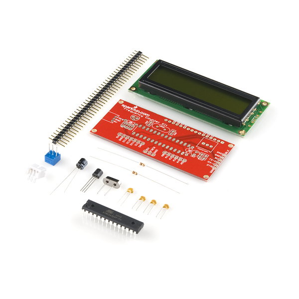
This kit is a re-hash of Nuxie's FunCount frequency counting kit. It includes everything you need to build a frequency counter capable of measuring frequencies from 1Hz to over 6MHz. The measured frequency is displayed on a 16x2 black on green LCD.
Our new design is based on the popular ATmega328. The ATmega comes pre-programmed with both the frequency counting firmware, and a serial bootloader, so you can program it as you would an Arduino. If you want to program it via Arduino, you'll need a FTDI Basic Breakout. Unused pins of the ATmega328 are broken out for all your custom firmware desires.
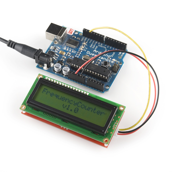
The ATmega328 runs at 16MHz, and should be able to reliably count frequencies up to around 6.4MHz (assuming a 50% duty cycle). Voltage supplied to the kit should be 5VDC. The voltage input on the frequency pin should not exceed the supplied voltage, and should not go below 0V.
The kit includes a 3-pin JST male connector, so you can use this wire to deliver +5V, ground and the frequency signal to the Counter. You'll also be able to piggy-back the counter onto our Function Generator Kit (see below).
Replaces:KIT-09003
Comments
Looking for answers to technical questions?
We welcome your comments and suggestions below. However, if you are looking for solutions to technical questions please see our Technical Assistance page.
Customer Reviews
No reviews yet.
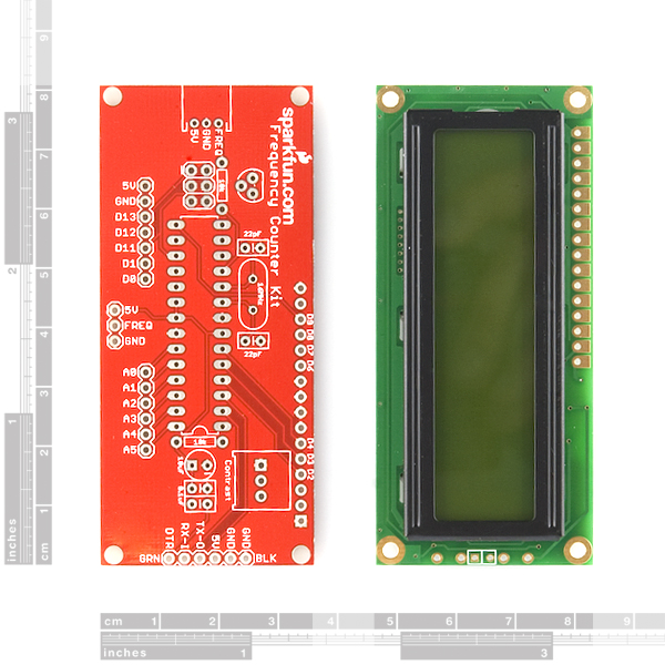
Looks like the two traces are on the same side. Seems like a Dremel tool and some conductive ink ought to be able to fix the problem--cut the two traces, clean the solder mask off from four spots, make one diagonal trace, and loop a second trace around in a C shape, crossing over a point with intact solder mask.
Am I missing anything?
The Eagle files show the RX/TX flip as corrected, but the photo shows them swapped. Which version are you currently shipping?
I seem to recall you announced the fixed version somewhere, but the description doesn't reflect that.
Fixed. We had a newer version uploaded, sorry.
You probably want to correct the description if you're shipping the fixed version.
We're not. I updated the Eagle files that match what we're selling.
Looking at the Arduino sketch, I have two questions that are probably just my lack of understanding
1. Why is the following line repeated twice? Is it a typo or is there some reason the counter needs to be read twice?
frequency = (TCNT1H << 8) | TCNT1L;
2. when resetting the counter registers, shouldn't interrupts be disabled? Most of the time it shouldn't matter but I think there is a potential race if a count occurs between the low byte and high byte being cleared?
3. For accuracy sake, shouldn't the counter registers be cleared immediately after reading? Right now I think you loose counts that occur between reading, doing the math, and updating the lcd.
Thanks,
--Rob
Any chance SFE will sell the PCB by itself?
Not at this time, but if we get enough requests, we can consider it.
I ask because black-on-green is lame. I want to make a white-on-black serial enabled LCD.