- Home
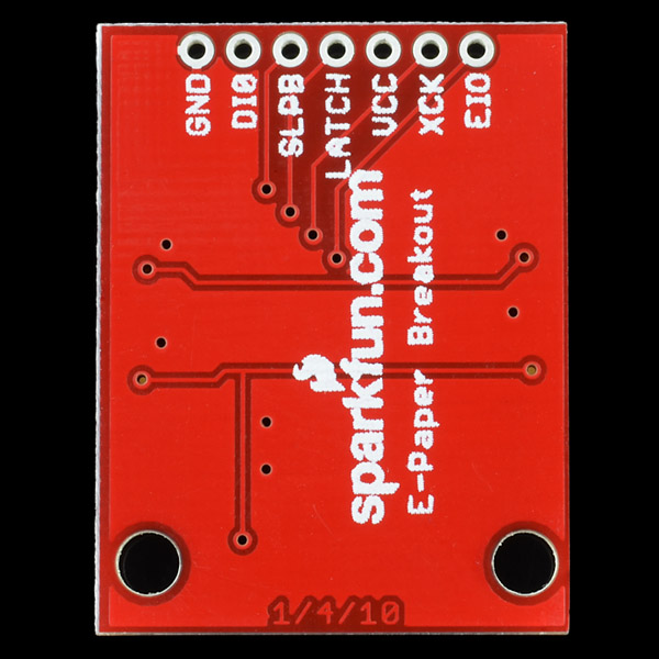
- SparkFun E-Paper Breakout

SparkFun E-Paper Breakout
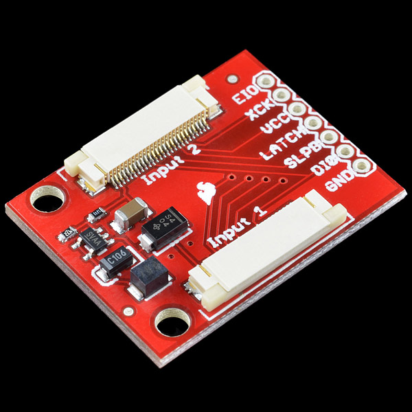
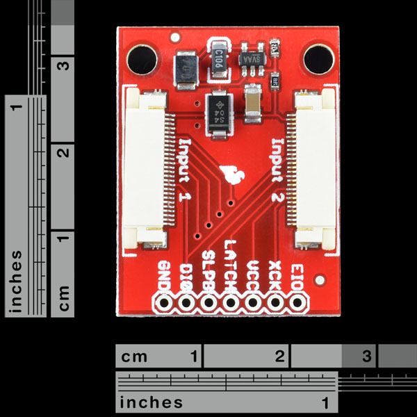
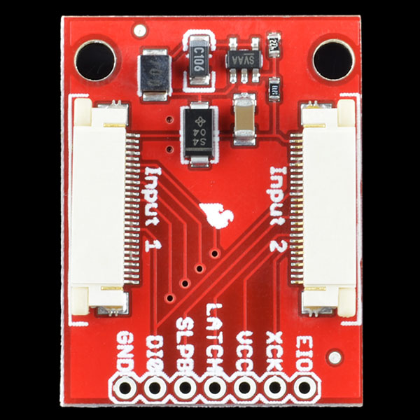
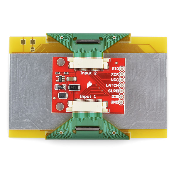
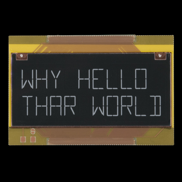
E-paper displays are rad. But those 26-pin SMD connectors can be a real pain to solder, so we put together a breakout board to help you integrate this very cool technology into your next project. This board breaks out all of the major pins from the e-paper ribbon connector to a 0.1" pitch header. Because the e-paper display requires a 35V supply, the breakout also includes a voltage step-up so that you can power the display using either 3.3V or 5V.
Note: The tab on the SMD connectors may be a different color than pictured.
- Schematic
- Eagle Files
- Datasheet (E-paper display)
- Datasheet (SMD Connector)
- Example Code
- bildr Tutorial
SparkFun E-Paper Breakout Product Help and Resources
Core Skill: Soldering
This skill defines how difficult the soldering is on a particular product. It might be a couple simple solder joints, or require special reflow tools.
Skill Level: Noob - Some basic soldering is required, but it is limited to a just a few pins, basic through-hole soldering, and couple (if any) polarized components. A basic soldering iron is all you should need.
See all skill levels
Comments
Looking for answers to technical questions?
We welcome your comments and suggestions below. However, if you are looking for solutions to technical questions please see our Technical Assistance page.
Customer Reviews
No reviews yet.
This board does not come with the E-paper screen which is a retired product. If you need this device and the screen try looking at our distributors.
Does this come with the E-paper display?
I googled the pants off this display, and although I found several people tinker with it, it looks like not many people, if anyone at all got this thing off the breadboard and into a finished product. I made a PCB for it and powered it off a 3.7V LiPo battery. Check it out: http://kevinrye.net/files/epaper_clock_final_assembly.php If you go to the bottom of the page, you'll see the older posts so you can see the project from start to finish. Full source files are posted too.
http://dangerousprototypes.com/2013/06/18/e-paper-clock-in-a-sick-of-beige-case/
I'm making a clock with the e-paper display and breakout. I am just going to add the breakout board to my PCB as a daughter board using a header. It would be nice if you guys had something for Eagle like a pad printing or something so we can better lay it out on our PCBs. I copy/pasted the outline from the breakout board Eagle file, but that doesn't help to figure out how much space the actual display takes up.
Request for a future revision: Breakout the enable pin of the regulator.
The step-up draws 15m continuously, hampering low-power usage.
This would also allow a proper shutdown sequence. The datasheet mentions the EPD should be powered down a few ms before the controller.
Will this work below 3.3v? The step-up datasheet mentions a minimum of 2.5v, but maybe there are other limiting factors.
What kind of current does the display draw while updating? The datasheet mentions a few numbers, but I can't really tell.
Hi, I'm new to electronics, and I'm having trouble connecting the breakout board with the E-ink screen. Do I just push the ribbon cable in? It won't stay. Any ideas? Thanks in advance! Xinkun
Quoting from the display's comments,
An observation about possible over current faults. I read the datasheet for the MIC2295, it does not mention any soft-start behavior. This would mean that the input current can easily exceed 1A for a few milliseconds, and this could trip the USB.
Why are there two input connectors?
Is it because the display is a 16x2?
I checked out the manufacturer's site and they have single-line displays... would those work with only one connector?
Each connector controls one line of the display. These 2x10 displays are essentially two of those single-line displays fused together.
This breakout would likely work with those single-line displays, if you just use the 'Input 1' connector.
http://bildr.org/2011/06/epaper-arduino/
could i connect two of these to one arduino and feed two screens with new text?
it might just be a matter of playing around with the EIO1pin ?
s.
i received a replacement display today and now it works. (thanks sparkfun)
i think the first one was slightly damaged. the plastic with the very fine connector lines in it seems to be just glued on to the rectangular body of the screen. in mine that slightly detached.
stephan.
Hi.
So, i connected the breakout to the display as shown in these images here and as described in the arduino file.
but if i plug the usb cable in with the breakout board attached to the arduino my computer says that too much current is drown.
I tired an external power supply (9V) to power my arduino nano. same story arduino does not power up.
As soon as i disconnect the breakout board the arduino comes back online.
any ideas?
thanks, stephan.
You might have an issue with your board or setup? It shouldn't draw that much current. And since your computer is telling you there's too much current being drawn, that usually means there is a short somewhere. Check your connections and the orientation of the display. If you still have issues, contact techsupport@sparkfun.com.
I have the same high current draw problem. Has anyone else been able to get one of these boards to work? I suspect there is a noise problem due to the boost converter.