- Home
- Product Categories
- Wireless and IoT
- GainSpan WiFi Breakout

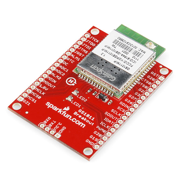
GainSpan WiFi Breakout
**Replacement: **None. The module on this board is retired so we can't build anymore, but check out our WiFi category for more modules and breakouts. This page is for reference only.
This is a breakout for the GS1011 ultra low-power wireless chip from GainSpan. The GS1011 device is a highly integrated ultra low power wireless single chip which contains an 802.11b radio, media access controller (MAC) and baseband processor, on-chip flash memory and SRAM, and an applications processor all on a single package. Along with its embedded software stack it offers a highly scalable, reliable, manageable and secure wireless link to meet the growing demand of wireless sensor networks utilizing the broadly accepted IEEE 802.11b,g,n standards infrastructure.
- Supports IEEE 802.11
- Seamlessly integrates with existing 802.11b/g infrastructure and utilizes the 802.11 security, manageability, ease-of-use, and quality of service
- 802.11i/WPA2 Authentication, AES Hardware encryption
- Optimized for battery powered application with very low power consumption for multiple years of battery life
- Range 200-300M+ Outdoor (Typical Estimate)
- Two 32-bit ARM7 CPU @44MHz, 1 for applications (APP) : 1 dedicated to radio (WLAN)
- 2 UART , I2C, 2 SPI, 2 ADC, 1 PWM, and 32 GPIO
- Operates at 3.3V
Comments
Looking for answers to technical questions?
We welcome your comments and suggestions below. However, if you are looking for solutions to technical questions please see our Technical Assistance page.
Customer Reviews
No reviews yet.
Hello guys, I've connected this device to netduino and encountered the problem with sending any commands. The only response I could get was an echo.
Command ATE0/r didn't seem to be working. Only echo back with the command.
Any ideas?
Thanks in advance.
So far, Gainspan module DOES NOT perform AP mode. AT+WM=2 as per the datasheet. That command returns ERROR: INVALID INPUT. The firmware that ships with the device does not even recognize this as a valid command! You are forced to sign a Non-Disclosure in the hopes of getting the firmware 2.3.1 to install (which it won't). So this device does not do what the datasheet says it will do. Neither Gainspan or Sparkfun will support you on this. Stay away from this device if you think it will do Access Point mode. It will not. It might be Sparkfun's breakout board that's causing the device to reboot every time I attempt to upload a new firmware...but I can't get any support so I don't know how to troubleshoot this.
That's not the only problem. AT&V shows the exact same settings as I used for AT+WA=MySSID,, and that command returns "OK" where ATA returns "ERROR" which doesn't help.... AT+WM=0 and AT+WAUTO=0,MySSID,, so ATA should not be failing. But ERROR doesn't tell me what the problem is.
UPDATE: 11/01/11 8:39PM - I was contacted by Michelle in Sparkfun's customer service who said she is looking into it for me. Keeping fingers crossed, will keep you posted. (Please note, I sent two emails to Sparkfun, one to try and get the firmware and a second once I had the firmware to ask about loading the firmware, which is what triggered her response, not my wanking here in the comments)
UPDATE: 11/04/11 11:04PM - I was contacted by Gainspan who told me I needed to pull G27 high (3.3v) during boot. Then I ran the gs_flashprogram.exe (installed from C:\GainSpan\EvalKit\2_3_1\tools\gs_flashprogram\gui_version folder) and selected the C:\GainSpan\EvalKit\2_3_1\WLAN Firmware (WFW)\bin\WFW-REL-2_0_27.bin file and the two from C:\GainSpan\EvalKit\2_3_1\userapps\Serial to Wi-Fi (S2W)\bin\Wi-Fi Protected Setup (WPS). I am now able to use these commands to manually setup limited AP mode.
AT+WM=2 AT+NSET=192.168.1.80,255.255.255.0,192.168.1.80 AT+WSEC=8 AT+WWPA=testing2 ATC1 AT+DHCPSRVR=1 AT+WRXACTIVE=1 AT+WA=Gainspan,,9 AT&W0
However, the unit will not take AT+WAUTO=2,Gainspan,,9 and therefore will not auto boot into AP mode. It also fails to understand AT+DHCPSRVR=1 and it doesn't seem to want to boot in any security mode other than "open."
can you please tell me from where you got the software tools?
Paul (or anyone from sparkfun),
Did you successfully get it into AP mode without buying a development board from gainspan? They are like $250 and I don't want to spend that kind of money. This is advertised as being usable as an AP and I've had the NDA approved but it seems we need to buy this other board just to switch the firmware!?
Thanks!
Hi all,
Does anybody experience the following problem
I did upgrade of FW to 2.3.5 version and after that the module doesn't response to AT commands but when I solder the PGM jumper again to PGM mode the gs_flashprogram can read the info from the module, I can read and change MAC address and etc ... It looks like that something wrong with software ...or
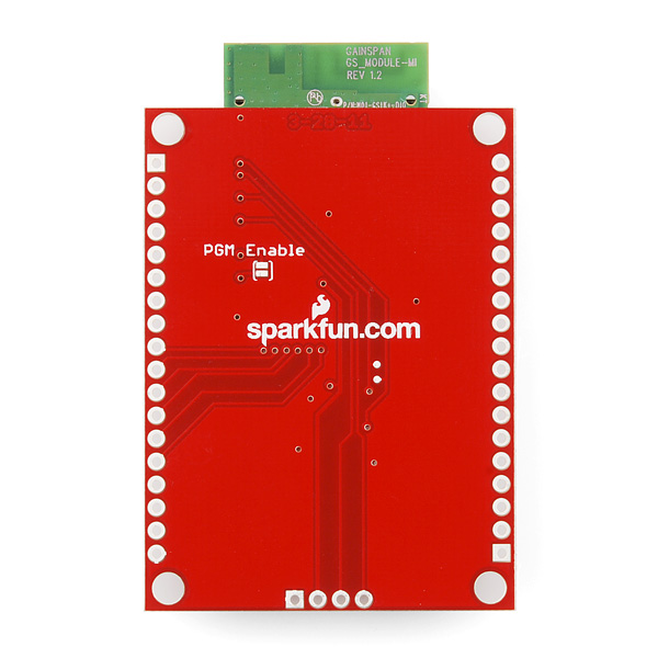
Does anyone know what the PGM enable pads on the bottom of the board are for. My guess is they are some sort of program enable feature and if so does anyone know how to use this feature?
UPDATE: I believe that my assumption was correct, if those pads are jumpered together, the board may be programmed via UART0. I will update again and let everyone know if I was able to update the firmware with AP mode via this method.
Is the U.FL connector on this usable?
A Gainspan WiFi library for chipKit and Arduino http://electronics.trev.id.au/2012/02/07/gainspan-wifi-library-for-chipkit-and-arduino/ Hope it's usefull to some.
Gainspan WiFi library for chipKit and Arduino: Hoping it to be useful to someone, have shared the work to update the wirefree library from diysandbox to be compatible with the chipKIT. http://electronics.trev.id.au/2012/02/07/gainspan-wifi-library-for-chipkit-and-arduino/
Gainspan WiFi library for chipKit and Arduino: Hoping it to be useful to someone, have shared the work to update the wirefree library from diysandbox to be compatible with the chipKIT. http://electronics.trev.id.au/2012/02/07/gainspan-wifi-library-for-chipkit-and-arduino/
has anyone got this working with spi?
Yes, finally! First, you need at least the 2.3 firmware. I am using 2.3.5. The module I received only had 2.2.
My MPU is an atmega328p. The programming notes in its MPU manual are straight forward for setting up the SPI and work as needed.
The problem I had arose from the GainSpan documentation. Although this module's manual has been updated to conform to the 2.3.5 firmware, it is lacking some details on the SPI interaction that make it somewhat misleading.
SPI interactions are full duplex. As the MPU is shifting bits out to be written, bits are being shifted in from the target device. Consequently, when the MPU is reading data from the module it must send idle bytes on the bus to generate the master clocking.
The GainSpan manual discusses an escape sequence for byte stuffing bus control including the special idle character. This is misleading in that you don't actually need to escape the idle character, just send it directly. This tripped me up for days.
The other secret is that the firmware implements the SPI as a completely binary interface instead of a character-based one like the USART uses. GPIO28 is asserted high when there are data available and goes low when the buffer has been completely read. The result is that the MPU must read everything from the module while GPIO28 is asserted.
The MPU will receive a bunch of idle characters as well as the character commands it is interested in for every complete buffer read. The application software will need to parse the characters from the buffer to extract the data it needs. This tripped me up as my software always stopped reading when it received the complete OK or ERROR response.
did you have to buy anything from gainspan in order to update the firmware? or did you only have to sign their NDA? thanks
I bought an evaluation kit so I could get the new firmware. The kit came with a USB TTL adapter, which was useful for easily updating the firmware on the breakout board. I also used the evaluation kit as a reference to debug my hardware and software. The kit was $260 plus shipping, but it saved me a ton of time.
has anyone got this working with spi?
I just wanted to report success with this on an Arduino Mega, as there have been a few people who have had difficulty.
Only needed TX, RX, 3.3v & GND
When using the Arduino IDE console to send AT commands, note that you have to send a CR for your AT commands to register as complete to the device : )
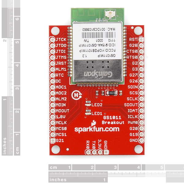
I don't see measurements???
thx
As per a GainSpan press release, dated Nov. 14/2011 "GainSpan Enables Access Point Mode on Embedded Wi-Fi Modules
Turns GainSpan enabled products into instant wireless access points; simplifies provisioning and improves ease-of-use ", apparently AP mode is enabled, providing what appears to be almost "seamless" provisioning of network access.
How long will it be before SF gets these as modules and/or breakouts?
Does anyone have any Arduino libraries for controlling this over SPI?
Does anyone have any Arduino libraries for controlling this over SPI?
Sorry about the formatting
++++++++++++++++++++
char buffer[100];
int idx=0;
void setup() {
Serial1.begin(9600);
idx=0;
SerialUSB.println("Enter command");
}
void printCommand(){
buffer[idx]='\0';
SerialUSB.print("command: ");
SerialUSB.println(buffer);
Serial1.println(buffer);
readResponse();
idx=0;
}
void clearBuffer(){
for(int x=0;x < 100;x++){
buffer[x]='\0';
}
}
void readResponse(){
idx=0;
clearBuffer();
delay(500);
while(Serial1.available() && idx < 98){
buffer[idx++]= Serial1.read();
}
SerialUSB.print("response: ");
SerialUSB.println(buffer);
clearBuffer();
}
void echoChar(char c){
SerialUSB.print(" char: ");
SerialUSB.print(c);
}
void loop() {
// clearBuffer();
if(SerialUSB.available()>0){
while(SerialUSB.available()>0){
buffer[idx++]=SerialUSB.read();
}
printCommand();
}
}
Just got this board and (because I mostly have no idea what I'm doing) have been only moderately successful.
Hooked up to a Maple board (an arduino board with a bit more power/memory and I/O). The board has multiple uarts (I'm using 1) and support for USB so the program will need a bit of mods for the Arduino
connected 4 wires pwr, gnd tx1 (wired to rx on the wifi) and rx1 (wired to tx on tlhe wifi)
This simple minded program below will allow you to enter the commands on the USB serial, submit them to the wifi and echo the response.
Hope this helps someone.
Here is the initial stuff I did to associate my network (my ssid=f3wk) I use wpa2 security
command: AT+WPAPSK=f3wk,mysecretkey
response: part of my secretkey
Computing PSK from SSID and PassPhrase...
command: AT+WA=f3wk
response: Gateway
192.168.1.99: 255.255.255.0: 192.168.1.1
OK
command: AT+NSTAT=?
response: .0 DNS2=0.0.0.0
Rx Count=26 Tx Count=883
I really don't like this thing. It's been nothing but problems for me.
It was a runaround to sign the NDA and get the documentation. Then I discovered (like others have) that you can't actually "program" the thing without an expensive sdk.
So I stuck with trying to interface with it over serial. Many of the commands taken directly from the documentation do not work.
I've wasted a month and I need to finish my project for December. I think I'm just going to rush order WiFly module and look at the Arduino libraries for reference.
Do the UART and/or SPI lines on the module need to be converted to 3.3V or can they interface directly with a 5V microcontroller? If they need conversion, what is the best way to do it?
Anyone get the http post working? The escape sequence is a bit different from TCP and I'm not having any luck with it. I'm sending:
at+httpsend=0,3,10,/test_post.php,23\r\x1BH
my server should be echoing back the data I send (works with putty) but it just sends back an empty string. I think I'm doing something wrong with the escape sequence.
In case anyone is wondering, I did get this working, here is the syntax:
at+httpsend=0,3,10,/[path],[data_length]\r\x1BH[data]
and what does the "\x1BH" represent? is it needed for a GET?
what do you mean here when you say data length? i think i understand it if you are doing a "POST" (i.e. the length or your post data?) but what is it referencing if i am doing a simple "GET"?
How does this connect to a specific wifi access point? Is this configurable to access a secure wifi connection etc...? Once connected, can you connect via sockets? or http?
Totally new to embedded electronics...wanting to add wifi capability to a project...
Wiring and connecting to my network was quick and easy.
I'm having trouble getting an HTTP GET command to work. I keep getting a 400 error - I don't think the request is getting to the server though. Any suggestions?
Make sure that your serial line is 3 line interface. The chip default is 9600, n, 8, 1
I just finished using this chip to make a WIFI interface for an LED sign that I'm going to use on my Christmas light show.
A writeup on the project is at:
http://mysite.verizon.net/vze33f7g/
Does anyone know the default serial settings? 9600 8N1? Getting nothing but gibberish.
Got a few of these. Got most of the documents. Read as much as I could. Now I have lots of questions:
- any quick start guide available?
- can you telnet/ssh to the module to access the commands or you must use a serial interface
- for the application processor, I heard about the NDA to sign to get more info. Where is the NDA?
- developments tools: anything eclipse based anyone would recommend
If this information is available in some other forum and I missed it, apologies.
Thanks - looking forward to working with this device.
Stephb, go to www.gainspan.com and register and it will give you the link to the NDA. Once you complete the NDA, you will have access to all of the programming guides.
Anybody get limited AP mode working?
Yes. You need to update the firmware to version 2.3.1. To do this you will need to sign an NDA with Gainspan and then they will give you the current 2.3.1 firmware.
Has anyone gotten one of these to work with an Arduino? If so, what is the minimum number of connections needed to get this fellow up and running?
I just connected the Gainspan to a Netduino Plus. Since the Netduino is pin-compatible with the Arduino, you should be able to do this with the Arduino too.
The connections you need are:
1. 3.3V on the Gainspan to 3.3V on the Netduino
2. Gnd on the Gainspan to Gnd on the Netduino
3. Tx0 on the Gainspan to D0 on the Netduino
4. Rx0 on the Gainspan to D1 on the Netduino
Check the Command Set document. It is very easy to communicate with it via the UART connection. Now I just need to figure out the WiFi side of it.
I've connected the Gainspan this way, but I don't quite understand how to communicate via UART?
Could you simply show me an example of how to send AT then read the response? Ideally somehow inside the serial console which is the same Serial as the Gainspan is using.
Thanks
I just got one in the mail. I'm working on integrating it with a Netduino. The connections should be similar for an Arduino. I'll post an update once I have it working.
I got one of these, and it has 4 contacts at the bottom of the board: VCC/GND, TX/RX... cool, but,
1. If I put 3.3V reg. to the VCC/GND, should one of the LED's indicate power on? If not, UhOh...
2. The chip wires up power a few different ways for various configurations: AlwaysOn, StandByEnable, DeepSleepEnable, etc... Which way is the shield wired up for?
Thanks!
Hey!
There's a schematic here... wonder what it has on it?
So, where's my RTFM?
Q2 answered, but not Q1, but more than likely from general ignorance...
No, neither of the LED's will not indicate power on. I just connected my new Gainspan board to a Netduino Plus. I sent an "AT" command to it and it responded with the string "OK", which means the module is transmitting and receiving fine.
Does anyone out there know of an instructable showing step by step how to wire and code to get this working with the arduino uno? We are trying to send sensor data wirelessly to a server. Thanks.
Does the SMTP work with GMail? I guess it could because the module also supports SSL?
And I also would like just the board... $30 sound good - but I don't need 5. Maybe Gainspan could give you a price break so you can sell at $30...
Hi guys,
Is there a way that guys can sell only the GS1011 module without the board? In case we wannna integrate it to a design.
thks
They did it http://www.sparkfun.com/products/10808
Also, does gainspan know you have their documents up on your site? If you go to their website, they require you to sign an NDA before they give you the datasheet (which seems kind of lame)
Gainspan most certainly knows. They were quite helpful in providing, in fact.
Will you be selling the module by itself? For people who want to save space and don't mind soldering tiny tiny wires?
Here you go http://www.sparkfun.com/products/10808 =]
Hi! is it compatible with Arduino Uno or Pro?
Ultimately it's compatible with any microcontroller, but it's not a shield, so you aren't limited to either.