- Home
- SparkFun Quadstepper Motor Driver Board

SparkFun Quadstepper Motor Driver Board
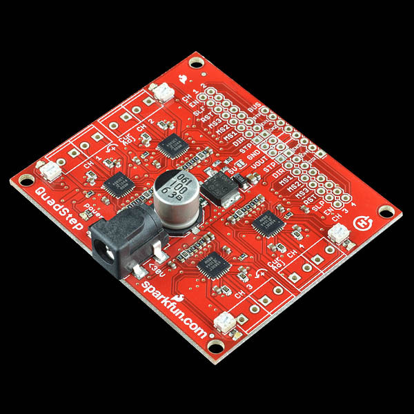
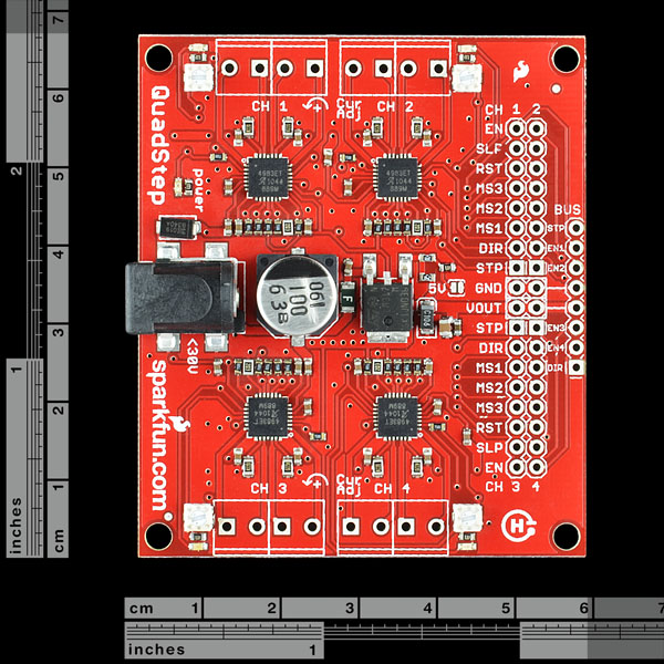
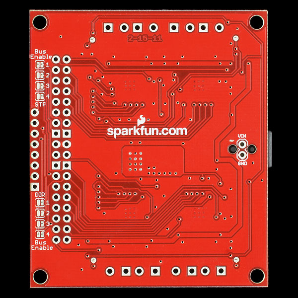
The Quadstepper motor driver board allows you to control up to 4 bipolar stepper motors simultaneously using logic level IO pins. Each motor driver has an output drive capacity of 35V and 1Amps. The board is capable of driving motors in full, half, quarter, eight, and sixteenth-step modes. The logic levels are selectable between 3.3V and 5V by way of a jumper. The bus header allows you to control all four motors with only 6 IO pins by controlling the enable (EN pins) for each motor, although each motor will be activated alone, not simultaneously. Be sure to close all of the 'Bus Enable' jumpers on the back of the board in order to use the Bus header.
The Quadstepper is a great board for 3D printing applications as well as a host of other applications where it's necessary to control precise movement from logic level IO pins.
Note: Although this board can theoretically supply 2A per motor, you will run into heat issues if you do not have proper thermal management (ie - heatsinks). Without heatsinking, you can expect to drive each motor up to 1A, which would be fine for our stepper motors, or something similar.
Note: The Arduino Library currently only works with an Arduino Mega or Mega 2560.
- Can control up to 4 bipolar stepper motors simultaneously.
- Each motor driver has an output drive capacity of 8-35V and 2Amps.
- Each channel uses potentiometers to control current to the motors.
- Capable of driving motors in full, half, quarter, eight, and sixteenth-step modes.
- Power input (barrel jack) needs to be less than 30V and supply enough current for your specific stepper motors.
- Jumper (labeled "5V") controls power to the motor drivers, logic levels, and VOUT pin, selectable 3.3/5V.
- Bus header allows you to control all four motors with only 6 IO pins by controlling the enable (EN pins) for each motor. Be sure to close the enable jumpers on the back of the board to use this feature.
- 2.1mm, center positive barrel jack
- Schematic
- Eagle Files
- Datasheet (A4983SETTR-T)
- GitHub (Design Files & Example Code)
- GitHub (Library)
SparkFun Quadstepper Motor Driver Board Product Help and Resources
Core Skill: Soldering
This skill defines how difficult the soldering is on a particular product. It might be a couple simple solder joints, or require special reflow tools.
Skill Level: Rookie - The number of pins increases, and you will have to determine polarity of components and some of the components might be a bit trickier or close together. You might need solder wick or flux.
See all skill levels
Core Skill: Robotics
This skill concerns mechanical and robotics knowledge. You may need to know how mechanical parts interact, how motors work, or how to use motor drivers and controllers.
Skill Level: Competent - You may need an understanding of servo motors and how to drive them. Additionally, you may need some fundamental understanding of motor controllers.
See all skill levels
Core Skill: Programming
If a board needs code or communicates somehow, you're going to need to know how to program or interface with it. The programming skill is all about communication and code.
Skill Level: Competent - The toolchain for programming is a bit more complex and will examples may not be explicitly provided for you. You will be required to have a fundamental knowledge of programming and be required to provide your own code. You may need to modify existing libraries or code to work with your specific hardware. Sensor and hardware interfaces will be SPI or I2C.
See all skill levels
Core Skill: Electrical Prototyping
If it requires power, you need to know how much, what all the pins do, and how to hook it up. You may need to reference datasheets, schematics, and know the ins and outs of electronics.
Skill Level: Competent - You will be required to reference a datasheet or schematic to know how to use a component. Your knowledge of a datasheet will only require basic features like power requirements, pinouts, or communications type. Also, you may need a power supply that?s greater than 12V or more than 1A worth of current.
See all skill levels
Comments
Looking for answers to technical questions?
We welcome your comments and suggestions below. However, if you are looking for solutions to technical questions please see our Technical Assistance page.
Customer Reviews
5 out of 5
Based on 2 ratings:
3 of 3 found this helpful:
Great all-in-one CNC solution
I bought this to run my homemade CNC milling machine, which it does just fine. I'm driving it with an Arduino running GRBL, so I used the separate STEP and DIR inputs. I bought some pin headers and the matching screw terminals and soldered those on for easy hookup. Works a treat!
Great product for many reasons, I'm disappointed it has been retired
This board is like 4 Big Easy Drivers combined into one, with shared components such that the necessary space for this board is far less than 4 individual BEDs. I used one in a portable 4 axis stepper controller project last year and it has handled around 2 amps per channel no problem after I thermal epoxied heatsinks onto the driver chips. My application requires only intermittent stepping/holding, so active cooling was not necessary even at such high power levels.
I was planning to build a second prototype of my project that's more streamlined and refined than my first but I learned that the Quadstepper has been retired. For that matter, so has the Mega Pro 5V board. I hate cannibalizing projects to build the next iteration, I like to have a personal development history I can look back on. It's been a sad morning browsing SparkFun!
Newbie at this kind of thing. Got this board and four of the linked stepper motors and I admit I'm thoroughly confused. Any chance you guys could produce a plain English tutorial on how to connect these up to a Raspberry Pi or BeagleBone Black? Can't find any discussion of this anywhere on the Net. Even the datasheet looks, to me, like it doesn't correspond exactly to the board I have. Thanks!
While the board looks complicated it really isn't. You have 4 identical circuits so just remember you have to do everything 4 times. There are basically 8 pins per circuit, but you can get away with using 2. You will need to make sure the enable pin on each circuit is grounded. By default it is set high turning the circuit off. Sleep by default is also disabled so you can leave it. Don't worry about Reset, it is pulled high and can be left as well. MS1,2, and 3 are used to set the step size. By default they are set to 1/16 of a step. You can change these if you'd like, but they work as is. Unless you want to change them in the middle of the program you can just hard wire any changes instead of using GPIO pins and adding it to your code. That leaves Dir and Stp. These are the 2 pins you will want to control from the GPIO pins on your board. Dir should be set as either high or low to determine the direction. Depending on your application this may or may not be changing often, but don't forget to set it. Lastly is the Stp pin. Basically every time you want the stepper to take a step turn this pin on and then off. Every time this pins gets turned on the stepper will take a step. (Note: you can't leave it on to keep the motor spinning, the motor only takes a step on the 'rising edge' or when the signal goes from low to high). So basically you just need to learn to control the GPIO pins on your board. If you have any other questions feel free to email techsupport@sparkfun.com.
What are you confused about specifically? You connect the pins on this to any GPIO pin, and then control them from software.
I just got one of these yesterday, and although it's not really a fault with the board, I really wish that the information found in the comments about the hole spacing for the motor connections was included in the product description above.
I didn't realize that the hole spacing wasn't .1" header compatible, and that without also ordering some of the 3.5mm screw terminals, the only other options (barring some clever macgyver-ing) are either directly soldering hook-up wire into the holes or using lone .1" snap-off headers (both of which are pretty 'sloppy' solutions).
It's not a big deal to just order some of the compatible screw terminals, but it would have been much more convenient to know ahead of time that this board is designed for 3.5mm pitch terminals for the motor connections.
I think this is important to know for people planning to buy one of these boards. It's an easy-to-miss detail of minor significance, but it's a waste of time, money, and shipping materials to have to make a second but almost unavoidable follow-up order for just a few cheap terminals (which results in the shipping cost usually being more than the cost of the order)
"The logic levels are selectable between 3.3V and 5V by way of a jumper."
Although this is said there is no clear indication where on the board this jumper is. I've found where I THINK it is and circled it in yellow on the pic in this link.
http://1.bp.blogspot.com/-K0bupIh-X4Q/TiCP3dGpnrI/AAAAAAAACw8/BKZkchERtDg/s1600/sparkfun%2Bjumper.png
Is this right?
That jumper is labelled as "close jumper for 3.3V.". Shorting it would select 3.3V.
On the schematic, yes, but nothing is noted on the board. Just trying to make sure.
I cross checked the schematic with the board design to make sure it was the same jumper.
I've looked over the documentation and have not been able to figure out which is OUT1A and OUT1B for channel A. How do I make this determination? (As in physically on the board)
EDIT: Figured it out. Download the Eagle software, install as freeware. Open the .brd file in the zip file above. Then go "View" > "Display/Hide Layers". Click on the "Top" (1) and "Bottom" (16) then OK. The wire tracks will be shown.
The schematic makes it look like the MS2 and MS3 pins are being pulled to VOUT/2 (internal 100k pull-down and external 100k pull-up), which isn't guaranteed to be high or low. I think you should be using stronger pull-ups.
I just ran into this issue too. It'd be nice to see an update to this board.
The datasheet suggests using high value resistors in this configuration.
I noticed that suggestion, too. However, that doesn't mean any high-value resistor is appropriate or the higher the resistor value, the better (e.g. can you see how 200k pull-ups would be a really bad choice?). When the consideration is current-limiting ability on a digital input, 30k, for example, would still qualify as a "high-value" that doesn't put the voltage on the pin in the no man's land between the guaranteed-high threshold (0.7VCC) and the guaranteed low threshold (0.3VCC). With 100k pull-ups, the voltage on MS2 and MS3 is 0.5VCC (because of the internal 100k pull-downs), which means the default microstepping state of the board is undefined. See the "Logic Input Voltage" specifications on page 4 of the datasheet.
I just bought this board and this still hasn't been fixed, 1.5 years later ... I mean just waving my fingers near the pin can be enough to change the microstepping mode, it's insane ...
A revision is in the works with this change. For now, you will just have to remove them or drive them with another pin, sorry about that. Although, in my testing, I was not seeing this behavior. Maybe check the solder connections as well.
Just got mine yesterday and noticed one thing. The holes for the motor connections aren't spaced right. They do not allow 2 3.5mm pitch screw terminals side by side for each motor. The distance of the holes is:
Just barely enough to not let my terminals fit in next to each other. Not gonna stop me from using the board but maybe the holes can be fixed to a more even separation. Maybe a 0.1" pitch would be better for space saving and allow for standard headers.
Big ups to SparkFun for all their work! Love these guys.
Sorry about that everyone, the correct terminals are listed below. If anyone got the wrong terminals based on our suggestion, contact cservice@sparkfun.com and let them know. Tell them Robert sent ya. Sorry again about that!
Ah, well better next time. I already did a work around (it's not neat) but it works.
The 3.5mm pitch screw terminals we sell fit just fine, however we did have the wrong screw terminals in the related items, which have been fixed now.
hmm... guess certain formatting isn't allowed. The spacing is 3.75mm between 1A & 1B and 3.25mm between 1A & 2B.
Aw... I fell into the same problem with mine today. I guess it's a real problem. The screw terminals wont fit on this board.
Does anyone know how straight forward this would be to work with in arduino? could this blogs tutorial and code be easily adapted? http://danthompsonsblog.blogspot.com/2010/05/easydriver-42-tutorial.html
Probably. However, the Arduino code will need some tweaking if you want to use more than one motor at a time.
I'm about to release a new version of the EasyDriver called the BigEasyDriver which uses the A4988 (or A4983 until we can get A4988s). They're working really, really well and should allow you to have 1, 2, 3 or more steppers hooked to your Arduino.
Is there a USB version of this board available? Something with Linux and Windows support? Also, does this board know GCode? Can it be used with Mach3 / 4 software? Thanks!
There is no microcontroller on this board, so there is nothing to know GCode. Connect it to a microcontroller and program it to understand GCode and you should be good (there are lots of libraries out there so you shouldn't have to write it yourself if you don't want to).
Hello everybody,
I'm new here and have some questions. I just wants to start with my new quadstepper. It is for a special 3D-Printer. As controller I have the RUMBA-board. Istead to use one DRV8825 I will take the quadstepper for the Z-axis. My objective is to control 4 motors with 6 pins.
Am I right to enable the 4 bridges for "ebable" and 4 "direction? The 5V bridge has also to be enabled? What else I have to do?
Thanks a lot for your comments and greetings from Switzerland Otto
I would like to drive 4 steppers simultaneously with the same motion profile. I obviously can hook all 4 sets of pins together but that becomes real messy real soon. Is there a way to accomplish this with the bus?
Hi guys, I am new to handle stepper motors and having some trouble with the sample program. Some errors saying that ""quadstep" doesnot name a type". Right now I need to synchronize two motors (out of four) at a time and I am not able to run even a single motor...
And I have Arduino 2560
I've made a little library with basic functionality: Quadstepper Arduino library
Hi guys, I am new to handle stepper motors and having some trouble with the sample program. Some errors saying that “"quadstep” doesnot name a type". Right now I need to synchronize two motors (out of four) at a time and I am not able to run even a single motor…
And I have Arduino 2560....can anyone help me with the initial setup for one motor....I think I can handle it if I can run one motor alone first...
I'm reading a 5V voltage out of the enable pins on BUS. Since these are logic inputs I'm concerned about this and whether the board is functioning properly. Does any one know about this issue?
In the schematic they are pulled to Vdd with a 100k resistor, so that's correct.
What is the max current on the Vout pins? I can boot a raspberry pi from the 5v pin but half way through it resets. Has anyone successfully booted their raspberry pi this way?
ATTENTION SPARKFUN: These shields are awesome! But the potentiometers are too delicate. They are too easy to mangle especially when they get exposed to heat. If one of the potentiometers gets too mangled it could prevent the entire shield from working. Please consider sturdier potentiometers or sell the shield without the potentiometers so we can solder on our own potentiometers.
I just finished a robotics class where 4 teams ran their motors on the quadstepper shield and I am sorry to say that 3 teams had the same issue and had to replace their shields.
Sorry to hear you had that issue! We are looking into sturdier potentiometers, but I will ping that again on our bugs to make sure it gets a bit of attention. Hopefully the teams still had a good time despite the hardware setback.
Does this controller support concurrent movement of the motors? When I try this only one of two motors is moving and if I disconnect the wires from the one that is moving, the second one starts moving (and stops again once I plug in the first motor). Am I doing something wrong, or does it simply not support this? Test source code for this: https://gist.github.com/anonymous/b667ebfed1659c85b82f#file-quadstepper-concurrent-test
Hello, I am new with this. If I am using this to power four stepper motors rated 12V and 0.5 amp, would the power source supplied to the Quadstepper Motor Driver Board be at least 12V and 2amps (4 motores x 0.5 amp = 2 amps)?
Can I use this with an Arduino Uno? I need to run all four motors simultaneously, is this possible? And where can I find heat sinks for this? I'm using the Accelstepper library and stepper accelerations require more current.
Is there anything test code for those trying to test the bus header?
I'm sorry but I just got this and am new to this device. I have the arduino mega, and two stepper motors. Does anyone know how to wire this up?
Just wanted to let you know that i opted for some stepsticks (instead of a quadstep) for my current project because there was no reaction to the problems i posted here, emphasising on the component / connector placement.
Thanks for your feedback! There is a revision for this in the queue, which will address most of your requests.
This piece of documentation seems strangely missing: Minimal wiring list for 1 whole step mode.
EN - low
SLP - high
RST - high
MS1 - low
MS2 - low
MS3 - low
a1zon - never mind. I see them, they are little white pots next to each channel's led.
alronzo - I don't see any trim pots on the QuadStepper driver board. Could tell me where you see them?
I smoked my QuadStepper motor driver board today. Though only one of four chips overheated, the entire board is now not functioning. I have only reciently made a few short test runs of my new 3axis CNC machine (it was working pretty well and I was writing "LinuxCNC" with it). I was turning the power supply for the motors off between short tests. During the last test runs, I heard some noise from one of the steppers and one of the chips started smoking. I turned off the motor power supply but it was too late to save the board. I knew the driver chips were getting hot, so I had fashioned heat sinks from aluminm angle and use some CPU heat sink grease that I already had. Apparently this wasn't efficent enough at removing the extra heat. I expect set backs like this when a building equipment, so I'll order another QuadStepper and try to correct some of the heat related issues with the following:
Question: The driver chip datasheet indicates that you can limit current with the reference voltage. Does anyone know how to adjust the motor current limit on the QuadStepper Driver Board?
Question: Is there a manual for operating/wiring this board that I missed somewhere?
About my CNC - Nema 17 ROB-10846 stepper motors for all axis. 36V 9amp switching powersupply found on IOffer (adjusted down to 31.5v) C10 - Bidirectional Breakout Board LinuxCNC to run the GCode
Sorry to hear about that!
There is a trim pot on the board that will adjust the current limit to the motors. You should trim the board so that each motor isn't drawing more than an amp or so (in a stall condition). The heatsinks will help, but the board quickly gets hot at 1amp per motor.
The A4983 datasheet along with the schematic should give you all of the info you need. The only pin connections needed are EN, STP, and DIR for each motor. The MS pins are pulled high and can be pulled low to set the step resolution.
Hope this helps.
hello people, I am having a hard time finding a proper power supply for the board. At the moment I have a 500mA with variable Voltage up to 12V. My motors are rated 1.7A/phase and 3V, and although this works (at >=9V, at least for 1 motor) its pretty slow. I wanted to ask you what is the proper proper power supply, to use the board with 4 of these motors in proper speed, and not being afraid to fry it (or have dangerous heat problems in general). thanks (my steppers are the ones sparkfun sells ROB-10846 )
First, the board will only support about 1 Amp per motor, unless you use some good heat sinking. If you want to run 4 motors at the full capacity of the board, you will need a power supply with at least 4 Amps. We don't sell a wall wart capable of this (you can use a bench supply), but you should be able to find a bigger power supply on amazon. Since you asked, we'll look for something to carry to better support the power draw of this board.
thank you for your reply. i'll try to find one at 4Amps total.
I was looking at the quadstep.cpp file and I was wondering what is STEPMIN and why is it set to 800 :)
That variable doesn't have a physical purpose, it is added to another variable and sets the delay time for PWM in the current control function.
thanks a1ronzo for your reply :) I can see it is used in void quadstep::current_control(int step) as step1 = STEPMIN + (_torque * 260);
to be honest, I am not sure I really understand current_control. I see that the result step1 is used in the delayMicrosecond to power the motor in motor_go but I don't understand why it is calculated this way. Why 800? If I change this value, say lessen it, it will lessen the delayMicroseconds thus speeding the rotation ? Then why do we have to do _torque * 260? Where does 260 come from?
Sorry for all those questions, maybe I am missing some basic mechanics rules. :)
I have created a project to drive one of these from an Olimex LPC-P1343 over USB. It provides 4 axes of step and direction as well as accepting forward and reverse limit switches for each axis. It would be even nicer if this board included some kind of processor with USB.
The motor_go function is a bit confusing, particularly the relationship between the step size and increment values. I keep getting an error in my Serial Window that reads "incorrect value for motor_go()." What is causing this? I don't see anything in the forums on this question.
Increments is how many steps to rotate the motor. If you put 10 increments for 1.8 degree step, you rotate 18 degrees.
Also, make sure you are selecting the correct motor number (values 1-4 only).
Is anyone else having trouble compiling the example in the library? I'm getting a definition/class error: 'quadstep does not name a type.' No changes were made to the Example and it's in the right place. -M
Udpate: solved one problem, have new one. The prior error was due to running the code and its libraries from inside a Dropbox folder. That's a no-no. I moved everything into the Documents > Arduino > Libraries folder and compiled and get a new error: " Error Compiling: In file included from quad_step_test.cpp:43: /Users/matthewepler/Documents/Arduino/libraries/quadstep/quadstep.h:12:22: error: WProgram.h: No such file or directory"
Clues? -M
Found the problem. In the .cpp and .h file included in the library, you need to change
to ->
This is if you're running 1.0.1. Not sure about other versions. This will also be true for any library written before this change in the Arduino software.
What do the green LEDs represent next to the motor's voltage potentiometers? I'm able to get two motors running well, but motor 3 is not running, only the green LED is lit. Any suggestions?
The LED is an indicator light on the STEP line. Take a look at the schematic and you can see where this connects for channel 3. If you are having problems with your board, check your wiring, power, soldering connections, etc. If you are still running into issues, please let us know at techsupport at sparkfun dot com.
hello there, can somebody advice me on how to connect this with an arduino. I've read the datasheet, but it refers to the chip and not the board. They don't actually share the same labels.
the quadstep has 4x EN/SLP/RST/MS3/MS2/MS1/DIR/STP/
and VOUT/GND (i guess these are VCC and GND from arduino. if so, GND must be connected with the steppers power supply GND under the board. correct?)
and it also has a "BUS" line of pins labeled: STP/EN1/EN2/VOUT/GND/EN3/EN4/DIR
i don't get how it has to be connected, what the BUS line stands for, and if I have to use potensiometers as the datasheet says.
and one more question. Is there a library to use the driver with UNO? and how do I set the "reset" state? thanks in advance
The best way to interpret what is going on with the pin labels is to refer to the schematic and datasheet together. The part in the schematic is labeled correctly (and so are all of the silk screen labels on the board). The quadstep is basically the example circuit in the datasheet repeated 4 times.
You need to power the quadstep externally, through the on board barrel jack, since the motors need a decent power supply (up to 35V and ~1A per motor). Then, VOUT is the output from the on board regulator. You can power your arduino with VOUT. Or don't worry about VOUT and just connect GND from quadstep to arduino and then control the bus pins.
If you are using an UNO, you must use the bus header and toggle the EN pins from each motor for control. If you want to control each motor simultaneously, you will need a lot of pins and use something like an Arduino Mega.
thank you, got that (except the header story) the libraries i found didn't seem to work, , so i built my own class, and i have one more problem. when i plug things up, the large condenser near barrel jack gets heat up,from the first minute. I dont know why. Maybe its the ground that has to go to the same as arduino. In my case, i use only channel 1 for the moment, so i connect the ground pin, to the arduino ground. Is this the correct thing, or do I have to do something else. someone mentioned grounding under the board, but i cant find something to get connected to
How can I drive a motor with 35V if the maximum allowed input voltage is 30V?
You should be okay with powering the board with 35V. We suggest 30V as sometimes the regulator can get a little warm, depending on what you are doing with the board.
I rewrote the arduino library to work with any arduino and cleaned it up a lot.
https://github.com/johnjamesmiller/quadstep
I also wrote about the changes I made and why: http://blog.johnjamesmiller.com/?p=21
Hi guys,
I just buy Quadstepper and I having some difficulties to make a motor run..please be patience, this is the first time that I try to control a stepper with PWM (before this I use a simpler serial controller)..I need simultaneous motor driving but with most things with fix or default values, so here what I'm doing for one channel/motor:
So, for basic test purposes, I just have connected to the micro-controller (a Roboard Rb-110) the: "Dir" and "Step" PINs. According to my oscilloscope, I'm sending the right test pulses, the "Dir" line is "Up" to 3.5v during the whole 1000uS period to indicate the direction and the "Step" line shows 100 Up/Down pulses of 500uS during the same period. The QuadStepper shows a Green LED On on the motor channel but the motor don't do anything, absolutely anything (already try it with 2 different bipolar stepper motors), I know that perhaps I have the motor lines incorrectly connected, but I know that even in this cases the motor should tremble or something...but nothing, nothing at all.
May be the pulses are too quick?, too fast?, too short?, what do you recommend?.
Finally one thing that I don't understand very clear: Currently the micro-controller is sending 3.5v as Up logic level, that mean that the "Jumper labeled 5v" on the QuadStepper should be "close" to "understand" 3v logic level?
In advance thank you very much.
Mauricio
please email techsupport@sparkfun.com. there is too much here to reply to in our comment section.
why is Rsense such a small package. Doesnt it see ~1Watt of Pdissipation when 2A is on the output?
Yes, you are correct, the Rsense resistors are not 1 watt. In an upcoming revision, we will correct this. However, the 2-layer layout prevents the board from running at 2A anyway. In other words, you will hit thermal shutdown at about 1A per motor driver due to the layout and the Rsense resistors that are currently on the board are fine for 1A.
Hi all,
I'm really frustrated with this board right now. It's the second one I've purchased in the past three weeks and I just can't get either of them to work with LinuxCNC and these motors: http://www.sparkfun.com/products/10846
I'm about to return the whole lot as they just don't seem to play nicely. The most I've been able to do is get the motor to hold its position and make a noise that sounds like it's stuck. I'm pretty sure everything is connect correctly as I've followed the datasheets to the letter. I'm using a 12V, 2.5A power supply to the board and trying to get it to work with just one of the 3V, 1.7A motor.
What am I missing...?
Make sure you are connecting the motor winding correctly to the board. Each winding should give you less than 10 Ohms on a ohm meter and each winding is connected to each pair of headers, for each channel. So for the motor you are using, there will be two pairs going into channel one, and each pair will have a very low resistance.
Also, try adjusting the trim pot.
Hello Sparkfun Community,
So I think I may have screwed up my Quadstepper motor driver board... I had prepared a sketch that could communicate an Arduino Mega controller board to the Quadstepper driver board. I ran the program using an 8 V supply (current limited to 1 A) to the driver board (the lowest end of the input voltage range) and had the output connected to an oscilloscope to monitor the response; since I am trying to run a motor with a very low input impedance, I wanted to test this out first so I didn't burn the motor up. I tried turning the voltage up a little to see the response and at about 15 V, the driver board shorted out. The maximum input voltage is supposed to be 30 V so I'm not sure what went wrong. Now, when I plug the power supply into the board, it limits the voltage to 1.31 V with a current of 808 mA. Do you have any idea what I may have shorted out or how I can troubleshoot it? I am new to these micro controllers so I hope I did not ruin anything. But it seems like a faulty component since I was well under the input limits.
Let me know if you have any ideas.
Thanks, Brandon
You should be able to use up to 30V on the input. Please contact techsupport at sparkfun dot com and they can help you out.
Thanks, I tried sending them an email last week and have not heard back yet...
Because the motor terminals are not labeled A or B, like they are for the easy driver and big easy driver, I am unsure how to wire my motors properly. I've looked at the schematic as well as the eagle file but it is still unclear. My wires are as follow: A (red, red/white) and B (green, green/white). That being said, and orienting the quadstepper with channels 1 and 2 on the top and 3 and 4 on the bottom (looking straight on at it), could someone please elaborate on how to connect my motor wires from left to right?
Hereh is a link to the motor wriing schematic:
http://www.google.com/imgres?q=haydon+kerk+wiring+diagram&um=1&hl=en&sa=N&rls=com.microsoft:en-us:IE-Address&rlz=1I7GWYE&biw=1280&bih=555&tbm=isch&tbnid=1wYd2-TL3h_xCM:&imgrefurl=http://www.haydonkerk.com/LinearActuatorProducts/StepperMotorLinearActuators/LinearActuatorsHybrid/tabid/73/Default.aspx&docid=3ezGtgt1T3teVM&imgurl=http://www.haydonkerk.com/Portals/0/site%252520images/Actuators/hybrid%252520linear%252520actuators/stepper_motor_linear_actuator_wd.gif&w=418&h=305&ei=lbJTT6zqJIHo0QGev4D3Dg&zoom=1&iact=hc&vpx=508&vpy=245&dur=1445&hovh=192&hovw=263&tx=117&ty=125&sig=113776035042348209545&page=1&tbnh=103&tbnw=137&start=0&ndsp=22&ved=1t:429,r:11,s:0
Hey I'd also like some more info on how to wire the motors to the board.
I'm using the ROB-09238 stepper. I think it is right but I'm not sure. Can I break them? How can I test it?
I wouldn't trust the colors. What you can do is test for continuity between any two wires. If you get less than 10 Ohms between two wires, you have found one of the coils, these two wires can be connected side by side into the screw terminals. You will have two sets of continuous wires for each channel/motor. Hope that helps!
I am thinking of getting this item but will it work with 57BYGH56-401A Stepper Motor? the motors rated current is 2.8A.
I would like some improvements for the next version:
Thanks for the suggestions! A revision is in the works and will address most of your suggestions.
Well... it's been more than two years and nothing changed about this badly designed module. As usual i will vote with my wallet and buy Adafruit or Pololu modules instead.
The schematics themselves are self-contradicting regarding logic levels:
So if the solder joint has to be closed for 3.3V, wouldn't that mean it's not the default?
Just to add more confusion to the mix, the silk screen near that particular solder joint says '5V'; this makes it sound like it should be closed to set logic levels to 5V.
Of course all it takes is a multimeter to determine the real answer, but obviously there is an error somewhere along the line, and it would be nice to at least have it documented if not fixed.
hej, I bought the arduino mega and tried it with the library - does anybody knows why I get this error? Please help me, thanks!
core.a(main.cpp.o): In function `main':
/Users/martha/Desktop/Arduino/Arduino.app/Contents/Resources/Java/hardware/arduino/cores/arduino/main.cpp:7: undefined reference to `setup'
/Users/martha/Desktop/Arduino/Arduino.app/Contents/Resources/Java/hardware/arduino/cores/arduino/main.cpp:10: undefined reference to `loop'
This isn't really the place for this, try asking on the arduino.cc forums. Most likely you're trying to execute the library, which won't work.
We (my robotics club) wanted to use this board to drive a development platform that we built. The issue is since its a ground based platform we have to move all 4 motors at once, we also only had an Arduino (regular, not a mega) on the platform.
I took the example library and modified it to work with the large expansion header, and also changed it to work with an Arduino. Here's a video of our test platform: http://www.youtube.com/watch?v=S9lyeU3BPmY
Here is the source of the modified library and a example Arudino sketch: https://github.com/ubrobotics/Sparkfun-Quadstepper-Motor-Board
Let me know if you have questions!
Hi WaHooCrazy7,
I'm interested to build a vehicle similar to this, could you please let me know what stepper motors you used to drive the wheels?
We used some escap P110 68's that we had kicking around our robotics lab. The data sheet can be found here for the motors.
I'd say any small steppers would work fine for a platform of about the same size, our biggest problem is the plastic omni wheels slipping due to a lack of traction, not a lack of motor power.
If you have more questions let me know.
Is there a heatsink someone can recommend for this board? I tried some of the stick on GPU memory heatsinks, but those are not enough or the A4983's are too small to stick to.
i think i need some advice on setup.
my steppers are rated at 7V/primary, 1.2A. (the 7V is printed on the motor, the 1.2A is from googling the p/n, and finding someone else's quotation of the specs in a portuguese forum, so is less reliable, but lets assume it's right, for now -- if anyone has an old Astrosyn catalog, i'd love to hear from you.)
the variables as i understand it are these: the motors are 8 wire, so i can run them either in series (raises voltage and lowers current) or parallel (does the reverse). in addition, the quadstepper driver chips do current limiting.
if i run the coils in parallel, i've read that the current requirement goes to 1.414 times the rated value, or 1.7A. and since the motor's power requirement stays roughly constant, the voltage goes down by .707 to 4.9V. so, can i run my motors from a 5V supply, using the current limit control to keep only provide 1A (the quadstepper max) to my motors? or should i instead run them in series, at 7V * 1.414 = 10V, so that they need only .85A? or, am i misunderstanding the parameters entirely? can i use the current limit the way i'm describing?
(i assume these are my only voltage options -- 5V or 10V, unless i simply don't use half the coils.)
thanks!
Is this a 4 layer board like the BED? My application uses a variety of NEMA 17, 23 and the occasional 34. For the 34 we've been limiting current to 1.8 Amps (Gecko Drive) but for cost reasons (and inventory) I'd like to use this (or the BED) for all our motors. I realize I'll need to heatsink. Also, confused on bus mode. Can I use this like 4 individual drivers running all four at the same time? Was planning to use one I/O to step two axis plus another I/O to step the other two axis. I'm using the Mini-STM32 (ARM Cortex) as my controller.
It's a 2-layer PCB. If you want to run the drivers close to their 2 Amp max, you will need significant heatsinking.
The bus mode just allows you to control the enable lines for each driver, so you can only drive one motor at a time.
If I understand correctly, the Big Easy Driver (BED) is a 4 layer board offering better heat dissipation, correct?
I am trying to use Bus Mode with an Arduino. I have one 12V stepper connected to it. I wrote my own code, I have 100ms 50% duty cycle. The motor moves sporaticly. I've swapped wires around.
Is anyone having success with bus mode?
Have you closed the step and direction jumpers on the back of the board? If you continue having problems, feel free to contact techsupport at sparkfun dot com.
I'm using this quadstepper board and am controlling it with a lilypad arduino 328 attached to a lilypad Xbee, linked to an Xbee explorer USB on a Mac. All seems to be working fine.
On the schematic, the VOUT seems to be provided by an LM317 Voltage regulator which is rated to 1.5A, so I'm planning on using the VOUT Pin to power the lilypads (The Xbee would use most power, it draws 215ma at 3.3V).
Does anyone know any reason why this wouldn't work or isn't a good idea?
What this needs now are Digital Potentiometers and I2C expanders. Being able to control this beast from 1 i2c bus and 4 step lines would be epic ness.
Could someone help me. I need to attach the Quadstepper to my
Arduino Uno board. I have tried to find the wireing data. It is
not there.
Is it possible to independently control all 4 channels from the same 8 pins without using bus mode?
On a breadboard, you would just short out the two adjacent channels if you used headers to mount them.
for example, let's say I want to move both x (ch 1 motor) and y (ch 2 motor) at the same time, or even all 4 motors at the same time. how can you do it?
How does pulling up logic input pins to VDD work? How do you define the logic level of the separate MSx, RST, SLP inputs?
Is that barrel jack a standard 2.1mm center positive?
Yep, added this to the product description.
does anyone have any advice on how to power this? would you look for a < 30v ac adapter with 2 amps or 8 amps?
That depends on how many motors you actually hook up. If you're driving a small enough motor then even 1 amp will do. The driver however can operate a bipolar motor at up to 2 Amps per phase. If running all 4 motors at 2 Amps per phase then it's 2 x 2 x 4 = 16 Amps worth of power supply you're gonna need.
I'm having trouble figuring out the power situation. what is your formula? amps x ?? x motors = total-amps . I found another guy saying to use a formula of sum-of-amps x .67 = total-amps
The right way to do it is MaxAmpsPerPhase * TotalNumberOfPhases, which in this case (with 4 motors) would be 2.0 * 8 = 16 Amps.
You will not be able to push that much current through this board without heatsinks, fans or both, and even then 16A is a conservative number (i.e. you can get away with slightly less). But that is the theoretical max that the board can draw.
You all need to do a higer power version of this capable of at least 3A. You simply cannot create a CNC mill with that cheap NEMA 17 motors that you sell.
So just get one of the cheap ones on E-bay then. Like this : http://cgi.ebay.com/CNC-TB6560-4-Axis-3-5A-Stepper-Motor-Driver-Controller-/320681960958?pt=LH_DefaultDomain_0&hash=item4aaa2265fe
3.5A, four channel, parallel connection to PC, for $50. You can't get more than about 2.2A out of the A4983/A4988s that are on the QuadStep. But I'd rather get stuff like this from SparkFun where I know they'll take it back if it doesn't work, and provide support until it does.
would that driver work for driving 4 steppers? bipolar parallel 2.8A/4V each. My PSU is a 48v/12.5a model. I have a geckodrive g540 but I'm trying to control my DIY CNC machine from firefly/grasshopper (an arduino plugin for rhino - cad program)
The driver I linked to from e-bay is only 3 axis, if you need to drive 4 axis then you'll have to search around for another driver. There are several on e-bay that are 4 axis. Note that many people have reported bad experiences with these types of really cheap electronics off of e-bay.
If you have a g540, why would you need more drivers?
thought that the g540s controller was replicated by the arduino and the two would clash. I guess I can just breakout the STEP/DIR pins from the DB25 input and hook those directly to my arduino? Wire up the relays/psu/vfd as required and go?
@awatanabe, have you had any luck with the G540 interfacing with the Arduino?
Correct. Not having a g540, I'm not 100% sure, but I believe you can disconnect the stepper drivers inside it and wire them to the Arduino.
No, the driver must be new, and from a reliable source. Cutrate ebay components will not do.
I've been tinkering with stepper drivers the last few days, and I just tried hooking up a 5-wire unipolar motor to a 4-wire bipolar drive, ignoring the fifth "common" wire. It worked fine, and even seemed quieter (I'm guessing because the magnetic fields are now symmetrical). Should work for 6-wire motors, too.
Is there any reason I shouldn't keep doing this? Unipolar drives are cheaper and simpler, of course, but if I'm just gonna keep a few on hand, I'd rather stock only a single type of drive, and bipolar drives seem universal. Thoughts?
You can use 4, 6 or 8 wire motors when wired correctly, using a 5-wire motor will usually kill a bipolar drive. I definitely would not recommend using it with a 5-wire motor.
Bipolar is supposed to be more powerful. How you managed to drive a unipolor motor with a bipolar driver I'd like to know. I use a VEXTA PK-266-02A, which is both BI and UNI; if that helps ya.
Hindsight being what it is, if the DIP header had two more rows with power connections symmetric about the center (without keypin 20), off-shelf 40-pin ATA/EIDE cables (round ones even!) and connectors could have been used to hook things up.
If I am not mistaken this is the first product with the Open Hardware logo on it! Yeah! This board looks REALLY nice, sixty bucks for the core of a 3D printer is really nice! I love SparkFun!
Good eyes! The H with the circle was our own OHW logo. We're switching to the official one as we go: http://www.openhardwaresummit.org/2011/04/07/oshw-logo-selected/
I don't really get the bus mode its is 6pins (4 enables, direction and step) vs standard 8pins(4 direction and 4 step). If you only have six pins available, it helps but 6 vs 8 is a minor difference and allows 4axis simultaneous movement which seems like a much bigger plus. I'm surprised that the A4983 are used here as the A4988 are the newer parts with a couple of protection features added.
The A4983 is capable of 2A but this only true when a heatsink is added, without a heatsink these chips will overheat with anything over 1 A.
Yeah, but the A4988s are impossible to get right now. I'm sure when they become easier to obtain SparkFun will switch over.
Using a 2-layer board like this and no heatsink, even with a really nice layout, I am only able to get around 1A/phase out of these drivers.
With a 4 layer board and 2oz copper, that goes up to 1.6A. With 4 layer board, 1oz copper and heatsink that goes up to 1.8A. With 4 layer board, 1oz copper, heatsink and fan, I can get 2.2A/phase.
I've used the A4983, with heatsink and fan, on the tiny polulou boards and was really never able to get more than 1.1 amps out of them for extended amounts of time where I was comfortable leaving the router unattended, wish there more robust drivers in here.
I just built up the v1.1 of my Big Easy Driver (next version of the EasyDriver) which uses an A4983 last night. I tested it for about 30 minutes at 1.8A with no heatsink, 24V input, running at a low speed (which is the hardest on the driver - heat-wise anyway). It was rock solid. It gets quite hot, but it never cut out at 1.8A/phase. (it did at 1.9A). So it's possible - I'm using a 4 layer board and very tweaked layout to achieve this. I have not yet tested the Pololu boards but will soon.
Thank you, for the hard work dude; you have no idea. I think I just burnt out my easy today running some code tests and I have no idea how that happened.
This looks like a great board for 3d printing. You can't use the bus mode though, because reprap/makerbot-style printers need most/all of the motors enabled constantly during a print.
I can keep turning the four stepper motor simultaneously? or should I just turn a single stepper motor at a time? I can use (EN pins) header and bus (pins STP) bus header and control the direction with the DIR pin of each channel and thus turning the four stepper each with the desired direction?