- Home
- Product Categories
- Buttons and Switches
- 5-Way Selector Switch

5-Way Selector Switch
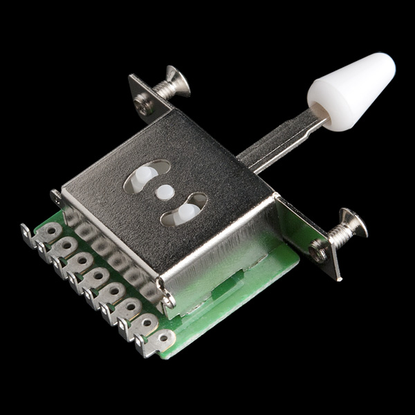
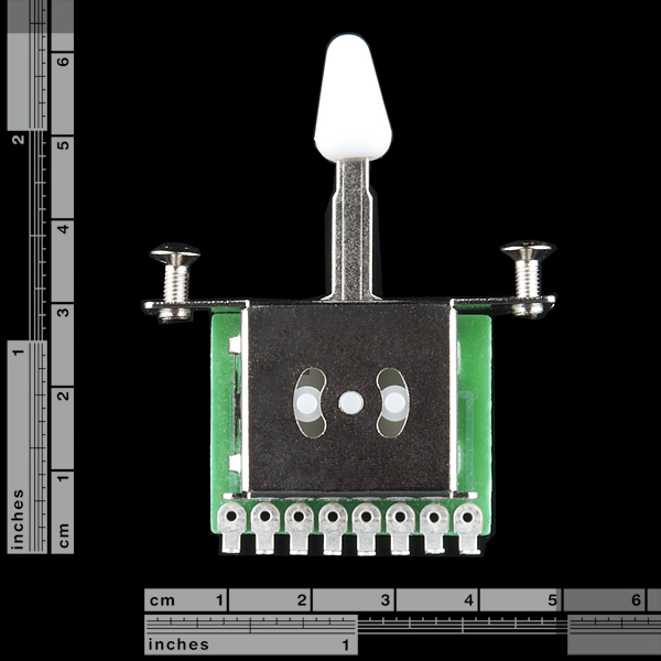
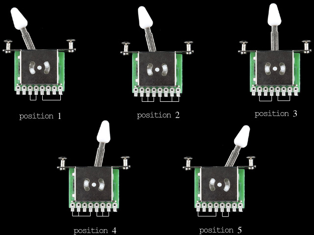
This is the type of switch you often find used as the pickup selector on electric guitars. The lever clicks through five different positions so you can select from three different inputs and a combination thereof. While this is, strictly speaking, a selector switch (albeit a switch with some strange permutations) It's also very useful as an encoder and by connecting it to a microcontroller you can read five discrete positions from three GPIOs. Check out the connection diagram below for details.
Note: Colors may vary. The PCB may be blue or green and the knob may be black or white. Functionality and specifications are identical, however.
5-Way Selector Switch Product Help and Resources
Core Skill: Soldering
This skill defines how difficult the soldering is on a particular product. It might be a couple simple solder joints, or require special reflow tools.
Skill Level: Rookie - The number of pins increases, and you will have to determine polarity of components and some of the components might be a bit trickier or close together. You might need solder wick or flux.
See all skill levels
Core Skill: DIY
Whether it's for assembling a kit, hacking an enclosure, or creating your own parts; the DIY skill is all about knowing how to use tools and the techniques associated with them.
Skill Level: Noob - Basic assembly is required. You may need to provide your own basic tools like a screwdriver, hammer or scissors. Power tools or custom parts are not required. Instructions will be included and easy to follow. Sewing may be required, but only with included patterns.
See all skill levels
Core Skill: Electrical Prototyping
If it requires power, you need to know how much, what all the pins do, and how to hook it up. You may need to reference datasheets, schematics, and know the ins and outs of electronics.
Skill Level: Competent - You will be required to reference a datasheet or schematic to know how to use a component. Your knowledge of a datasheet will only require basic features like power requirements, pinouts, or communications type. Also, you may need a power supply that?s greater than 12V or more than 1A worth of current.
See all skill levels
Comments
Looking for answers to technical questions?
We welcome your comments and suggestions below. However, if you are looking for solutions to technical questions please see our Technical Assistance page.
Customer Reviews
No reviews yet.
Cool! As a kid, I always dreamed of one day getting myself a "Five Position Binary Grey Code Encoded Position Sensor." And now it can be mine!
I'm using a 4028 BCD to decimal decoder to obtain 5 discrete logic lines. Gray "counts" in a different order than BCD. As the switch is moved the sequence from the 4028 is 1, 3, 2, 6, and 7. Cheap decoding without a micro!
The great thing about these for guitar use is that they are usually 'make before break' switches in that the second connection is made before the previous one is broken. This ensures continuity of sound in guitar applications. If these are the same, you should mention that feature.
It uses Gray code. The whole point of Gray code is that there is no transition where a "make" and a "break" both happen, so it's neither "make-before-break" nor "break-before-make", as far as I can tell. I might call it "make-or-break", I guess.
However, reading a later comment on how this switch is used in guitars, I think it could (actually, necessarily would) be a "make-before-break" switch if you're thinking of it as a three-position switch with half-positions, rather than as a five-position switch.
Customer 528199's comment appears to have gotten deleted (possibly in a slightly overly broad sweep of getting rid of spam). Here's their question again, hopefully avoiding the spam trap:
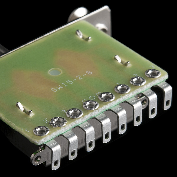
To answer: Check out the last image in the product page that shows the bottom of the switch. The two pins in the middle are COM, while Pin1-Pin3 live on either side of it, in sequence.
According to the code example, you only need to hook up half of these, so let's say you just hook up 1-2-3-COM (and leave COM-1-2-3 be). The COM pin would go to your Arduino's VDD pin (or any other part that shares its power supply), while - in the example - Pin3 goes to arduino pin 2, Pin2 goes to arduino in p3, and Pin1 goes to arduino pin4. You can probably change these around, as long as you define in the code which pins you're actually going to be reading. For each of those connections, you would add a resistor (10kOhm is suggested) between the pin and GND, so that they default to a LOW state, and as the switch moves around, pins go HIGH.
The code should be self-explanatory as to how it's determine which of the 5 positions the switch is in, based on just the 3 pins.
So, no mechanical diagram?
I had some expectation that it was a 5 position toggle switch with a common lead, but found the example code and diagram more than sufficient. Overall I'm happy to only be using 3 pins instead of 4/5 for the same . The sample code has the worst combination of brace styles I think I have ever seen, but it is pretty simple and easy to follow.
Haha...wow, you're right about the bizzare brace style.
question: does anyone know where to find a square switch plate for this? something that can be easily written on or etched to label the 5 positions?
I hang out in just as many electric guitar forums as I do electronics forums. But I must say I've never seen a discussion quite like that so far about the Stratocaster 5-way pickup selector switch ! :-)
The Strat has 3 pickups. The 5-way switch, as conventionally wired, allows them to be selected alone (positions 1,3,5), or in pairs (positions 2 and 4).
Most guitarists who tinker with the wiring of their guitars require a wiring diagram to make sense of this switch, along the lines of 'the red wire goes here, the blue wire goes here', etc. Few understand, or care, how the switch actually works. Unfortunately every pickup manuafacturer uses a different wiring colour code. So guitar forums are full of messages from people who wired up their guitar 'according to the diagram', but their guitar doesn't work !
The switch comes in a number of different forms, of which the one sold here by Sparkfun is only one. See the 3-part series here, where it is described as 'Far East 5-way Switch ':
http://www.premierguitar.com/Magazine/Issue/2009/Feb/The_Anatomy_of_the_Stratocaster_5_way_Switch.aspx
I am sure Jimi Hendrix would have been pleased to know he was actually using a "Five Position Binary Grey Code Encoded Position Sensor".
I have a customw-wired 5-way 'superswitch' on my Telecaster, which is another beast altogether .... a 4-pole, 5-throw lever switch ...
http://www.stewmac.com/shop/Electronics,_pickups/Components:_Switches_and_knobs/Super_Switch.html?tab=Instructions#details
Right? I've built a few guitars in my time and if nothing else I hope this post provides some of those guitarists with a readable pinout of this type of switch, haha. I had to sit here and ohm it out just to be sure I remembered right.
As the description notes, it's NOT a 5 way selector switch. It's a two channel switch that can select 3 different pairs of sources in several combinations. IE: 3 stereo channels can be selected one or two at a time. Not all possible combinations are available, that would take a 6 position switch. I'm not a guitar player so I don't know how this switch is used in that application.
I thought we mentioned this. It has 5 positions, but it's not necessarily connected with 5 pins and a single common pin. Just check out the connection diagram, you can easily read 5 discrete positions from this switch.
Hi Robert,
The issue is the the product description is ambiguous and misleading.
You can't say something is "in a way" x and say it is "actually" x; it's a contradiction. It makes one wonder, which is it, in a way or actually.
The misleading part is, it's not remotely a 5T switch. The similarity ends with the 5 positions.
A more accurate description would be, it's "a dual, 5 position binary Gray Code encoded position sensor, in a panel mount toggle switch form factor".
To shorten that, it's a dual 5 position, 3 bit, Gray Code selector switch.
Thanks,
-Mark
I'll rethink it.
It is a 5 position switch though, and most people might not really fully grasp the concept of a "binary grey code encoded position sensor".
Technically, it's not a switch, it's an encoder.
I agree with you, most people won't grasp the longer description, that's why I gave you a shorter one too.
The major missing detail in the description is that it's a Gray Code encoder. If people don't grasp that, they won't be able to use it. They'll just wonder why it has such a strange set of permutations.
If you tell them it uses GC, and link the words "Gray Code" to wikipedia, its "strangeness" will suddenly make perfect sense.
-M
P.S. When they know what it is, they'll realize it has inherent debounce, and they won't have to implement that in s/w. (or you can tell them)
I wrote the description, and you are correct about the grammar, it's definitely poor practice to in a way, practically, sort of write just like that.
This is a switch though, using it as an encoder (while that is why we carry it) is not what it was designed to do. It does it well and we encourage you to use it that way (see my example code). However, this is really a switch designed for a very specific purpose (guitar pickup selection) the output of the switch is not read as 5 discrete positions in a guitar but truly is used to mix 3 analog signals.
You are correct though, most people here will be using the grey code output of three pins to determine it's position, thus making it an encoder. Interesting, I've never examined the difference this carefully.
1 analog input pin and 4 resistors should work, as would three digital pins.
One digital pin and a 555 timer.
cant wait to see who has the easiest way to connect this switch to an arduino with the fewest pins used