- Home
- Product Categories
- Current
- AttoPilot Voltage and Current Sense Breakout - 45A

AttoPilot Voltage and Current Sense Breakout - 45A
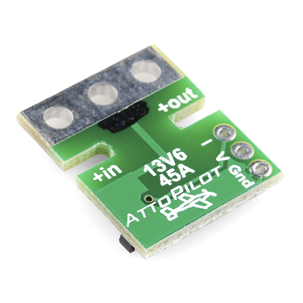
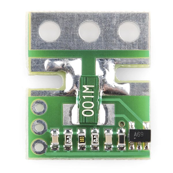
This is a small voltage and current sense PCB. DC current is determined by measuring a voltage drop across a pair of parallel shunt resistors, then converted to a final analog voltage output by the TI INA-169. Voltage sense is accomplished by scaling to 3.3V ADC range by a precision resistor divider.
The PCB is supplied without leads or connectors. The pad sizes are large enough to accommodate 12 gauge heavy duty leads (see datasheet) but care must be exercised in soldering. Smaller gauge leads are considerably easier to solder without creating shorts.
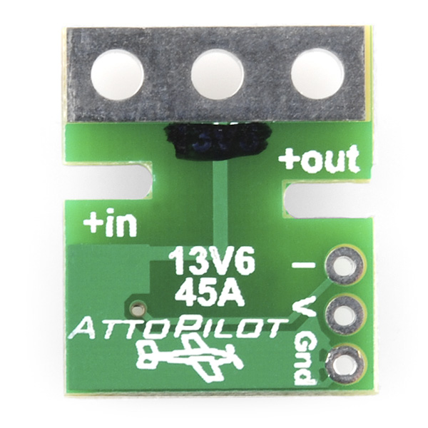
- Input resistor divider scaled for 13.6V Input voltage (recommended)
- 51.8V Max
- 44.7A Max
- Very low zero current offset
- Analog current output scaled for 3.3V ADC
- Self Powered
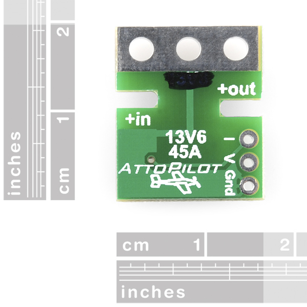
- 4 x 15 x 19mm
- [Datasheet](http://cdn.sparkfun.com/datasheets/Sensors/Current/DC Voltage and Current Sense PCB with Analog Output.pdf)
- Example Sketch
AttoPilot Voltage and Current Sense Breakout - 45A Product Help and Resources
Core Skill: Soldering
This skill defines how difficult the soldering is on a particular product. It might be a couple simple solder joints, or require special reflow tools.
Skill Level: Noob - Some basic soldering is required, but it is limited to a just a few pins, basic through-hole soldering, and couple (if any) polarized components. A basic soldering iron is all you should need.
See all skill levels
Core Skill: Electrical Prototyping
If it requires power, you need to know how much, what all the pins do, and how to hook it up. You may need to reference datasheets, schematics, and know the ins and outs of electronics.
Skill Level: Competent - You will be required to reference a datasheet or schematic to know how to use a component. Your knowledge of a datasheet will only require basic features like power requirements, pinouts, or communications type. Also, you may need a power supply that?s greater than 12V or more than 1A worth of current.
See all skill levels
Comments
Looking for answers to technical questions?
We welcome your comments and suggestions below. However, if you are looking for solutions to technical questions please see our Technical Assistance page.
Customer Reviews
3.5 out of 5
Based on 4 ratings:
1 of 2 found this helpful:
Current Sensor Doesn't Work
It just doesn't work. Tech support didn't help either. Terrible product - do not buy.
it was for my 500 helicopter but I haven't flew or yet
I needed this item for my air wolf 500 with a apm.
works great for monitoring battery usage and state of charge
using this to monitor 12V SLA battery connected to a 10A solar charge controller. watching power come in and out. awesome!!
Very happy with this conveniently packaged board
Once calibrated it is very accurate.
Has anyone used AttoPilot 45A with an Electric Imp? It's sitting between a 15W 12V solar panel and the charger circuit, but I get 65535 on the V pin and 0 on the I pin. Any idea why?
Huh, turns out my solar panel is at 22V in bright sun, so that explains maxing out the V pin, but what about the I pin?
Hi, I need a 1.1v instead of a 3.3v output for my project, on the current pin. I added a 10k and 4.7k voltage divider on the output to scale it to 1.1v, but I'm not getting the readings I'm expecting i.e. the output voltage barely rises when a load is applied. Either I'm doing something wrong, or I blew up the INA169 with my soldering iron. Is it a temperature sensitive chip? Any tips?
Main thread here: http://forums.openpilot.org/topic/15573-openpilot-boards-feeding-minimosd-via-uavtalk/page-39#entry327412
I am seeing a problem with linearity in the amp output. It's not until 6 amps or higher when the output becomes somewhat linear. Looking at page 4 of INA169 spec sheet, this makes sense. The graph "Output Error vs Vin" shows that minimum Vin for small output error is around 10mV. To get 10mV across a 0.001 resistor you would need 10 amps. I would like to measure amps down to 0.2 but the readings would be way off if using just a scaling factor. I wonder if the INA282 and a 0.005 shunt would have been a better choice.
in the Datasheet I found : 13.6V/45A = 242.3mV / Volt 73.20mV / Amp and from that I could calculate V = A0/4.127 and I = A1/13.66 but in the Example Sketch I found that V=A0/49.44 and I = A1/14.9 Which one is the right one ?
for some reason, my current readings for this sensor is not accurate at all !
If I power an UNO or a MEGA via USB, I get accurate readings, but if I power it via Vin (5v) the readings are off. 5v reads 6.2v and 12v reads 14.7.
Is this because it is scaled for 3.3v? In any case, is there a solution?
This is great, but for my application I need a sensor with a digital output. Does anyone know of such a product? Your help is much appreciated.
I am using the INA219 for my Nixie Multimeter. Works great. You can find an accuracy comparison with my MMC on youtube: http://www.youtube.com/watch?v=PNYnFTeADow
Until they are made available here, the Deans Ultra Connectors can be found at www.towerhobbies.com
I went this route to avoid soldering wires directly to the board and enable this to be used in different projects.
Is there any advantage to getting a low amps one over a high amps one? Thyre the same price.
Higher resolution. Anyway you can resolder resistors changing characteristics to your taste.
What's the correct maximum voltage on the 45A version of the AttoPilot?
Your copy states "51.8V Max", but the datasheet begs to differ, claiming "New 13.6 V / 45 Amps".
The datasheet states 13.6V in multiple places...
Thanks,
-Mark
When used with a regulated 12v power supply and a constant 1 amp draw it reads correctly, but when the power is bumped up to 30 volts at 1 amp, it goes off-scale high (1023). What gives? Is the product listing wrong here or is the datasheet? If I would have known only the 90 and 180amp versions could handle the higher voltage then I would have spent my $20 each on those x3
UPDATE 8/2/2011: Be aware that this version (45A) can handle up to the 51.8v without smoking the sensor itself, the voltage divider circuit will easily exceed 5 volts if you attempt to sample the higher voltage since, unlike the current, it WILL NOT scale the voltage down to a 3.3v level. In short, if you need to sample voltage from anything higher than 13.8v then you may want the 90A or 180A version instead which will correctly scale the higher voltage (at a slight loss of resolution).
Arduino A/D inputs smoke quite nicely when you put high voltages into them 8/
Correct, the sensor is designed for 13.6V, however it will operate up to 51.8V. 13.6 is the recommended operating voltage, as shown in the datasheet, and here on the product page. both are correct.
30V is going to result in about 7.3V analog out on the voltage sense channel. These sensors (45A, 90A, 180A) were designed for use with the AttoPilot UAV autopilot system to sense voltage and current being pulled by electric propulsion motors for small electric UAVs. The majority of AttoPilot users employ typical 3s LiPo batteries, so this sensor (13.6V and 45A) was made to get maximum sensitivity in this application. 3s LiPo is 12.6V at maximum charge.
And under the black place on the PCB is written 13V6.
Shouldn't this be considered passive, as opposed to self powered?
No - passive is for the voltage sensor part (simple resistor divider) however the current sensing side uses an IC, the TI INA169 (or INA139 in some cases). "Self powered" in that you don't need to supply an extra source to power the INA169, it grabs a few uA from the sensed power.
Ah, that makes sense. I should have read the datasheet.
What a great tool!
But I'm confused why this is ~$20 USD. The chip is $0.95 each for quantities over 1000 @ TI's website. All that's left is a small PCB and a few resistors. I understand the traces have to be wider to support 45A, but that's still not a lot of copper. What am I missing? I'd love to buy a handful of these, but I can't justify the cost at ~$20 a pop.
Yeah, I am struggling with the price point of these too. If they were $10 a pop I would take three. I am sure the VM would still be very healthy at $10
And while I agree "as always, $$ = time, labor, effort." profitability can also be about smaller $ margin x larger quantity.
Hi guys - my goal here is to add understanding and not prove your feelings are wrong. Besides INA169 at $1.50/each in the Qty I buy (< 1000), there is the shunt ($1+) and precision 73.2 k Ohm 0603 resistor ($0.40) and PCB, time, labor, assembly, inspection. Then shipping, SFE markup, etc... Plus taxes paid for the privelage of earning a living in the USA. If $20 is too much, the spec sheet clearly shows the circuit diagram, and know that at Digikey you can buy the parts in single unit qty for not too bad a markup (because Digikey seems to know that prototypers like us drive innovation and lead to later sales for them in larger Qty). You can buy presensitized 2-side copper clad boards from MG Chemicals and print the circuit layout on transparencies from an inkjet printer, then expose, develop, and etch the PCBs. Or you can use a permanent marker on copper PCB from radio shack for at least the shunt parts (SMD), etch, and the other parts breadboard and connect to the shunts.
as always, $$ = time, labor, effort.
nice, I was thinking on buying a current sensor... now I may buy this one :P