- Home
- Product Categories
- Cellular
- ADH8066 Evaluation Board

ADH8066 Evaluation Board
Replacement: None. We are no longer carrying this evaluation board in our catalog. This page is for reference only.
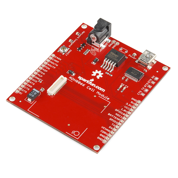
The evaluation board for the ADH8066 Cell Module breaks out all the pins to the module and provides you with the necessary support hardware to get you up and running. The ADH8066 board attaches to any USB port and appears as a standard com port. Power up the board with 6-12 VDC, turn on the module, and you can start sending and receiving AT commands via HyperTerminal or your favorite terminal program.
The board comes assembled as shown so you don't need to mess with soldering the 50-pin narrow pitch connector. We've also added pull-down resistors to the LED circuits and moved around some traces and solder jumpers to be compatible with hardware flow control.
Note: To turn the unit ON to send commands, the ON/OFF button must be held down during power-up until the 'Command' LED comes on. See datasheet below for more information.
Note: Some USB ports cannot source enough current to power the ADH8066 module. If the power supply is inadequate, the module may shut down while attempting to connect to the cellular network. An external power supply will correct this problem if it is experienced.
Replaces:CEL-10164
- Schematic
- Eagle Files
- [Datasheet](http://cdn.sparkfun.com/datasheets/Cellular/ADH8066 data sheet V1 4.pdf) (ADH8066)
- AT Command Reference Manual
- Enhanced AT Command Reference Manual
- FTP AT Command Reference Manual
- FTP AT Command Reference Supplemental
- Hardware Application Notes
- Software Development Guide
ADH8066 Evaluation Board Product Help and Resources
Core Skill: Soldering
This skill defines how difficult the soldering is on a particular product. It might be a couple simple solder joints, or require special reflow tools.
Skill Level: Noob - Some basic soldering is required, but it is limited to a just a few pins, basic through-hole soldering, and couple (if any) polarized components. A basic soldering iron is all you should need.
See all skill levels
Core Skill: Programming
If a board needs code or communicates somehow, you're going to need to know how to program or interface with it. The programming skill is all about communication and code.
Skill Level: Rookie - You will need a better fundamental understand of what code is, and how it works. You will be using beginner-level software and development tools like Arduino. You will be dealing directly with code, but numerous examples and libraries are available. Sensors or shields will communicate with serial or TTL.
See all skill levels
Core Skill: Electrical Prototyping
If it requires power, you need to know how much, what all the pins do, and how to hook it up. You may need to reference datasheets, schematics, and know the ins and outs of electronics.
Skill Level: Competent - You will be required to reference a datasheet or schematic to know how to use a component. Your knowledge of a datasheet will only require basic features like power requirements, pinouts, or communications type. Also, you may need a power supply that?s greater than 12V or more than 1A worth of current.
See all skill levels
Comments
Looking for answers to technical questions?
We welcome your comments and suggestions below. However, if you are looking for solutions to technical questions please see our Technical Assistance page.
Customer Reviews
No reviews yet.
Will there be a replacement for the ADH8066? Do we know anything about it yet? I see the wireless section here doesn’t even have a cellular category anymore.
ah, nevermind, I see the cellular category is not under wireless and there already is the “SM5100B” board. I will look at that.
Currently, that is going to be your best bet. We are working to find a reliable source of modules as replacements, but it's been slow going thus far.
Why they are selling it again if it was discontinued?
We still have modules left, so we are making enough boards to sell off the modules.
Does anyone know why this board has been discontinued?
The ADH8066 module has been EOL'ed by the manufacturer.
I have a problem with the module using this board, when I connect TX of the micro to RX of the gsm module it power ups the module and dont know why ¿? and I can't communicate with the module, I already desolder the jumpers and still isn't working. Can anyone help me?
is it absolutly necesary desolder the jumpers of the TX and RX by USB to use the break out pins with a microcontroller? 'cause i'm trying to comunicate with the micro using this pins and I cant.
Sadly yes. You could try using a razor or xacto and cutting the traces if you can't desolder it. Though desoldering with solder wick is the way to go if possible.
And what about the flow control pins? the problem I have is that i cannot communicate with the module using the usart of the pic18f4550. I send "AT" and nothing happens is like its not receiving anything
Okay, just to make sure these are all the parts I need to build a SMS modem: CEL-08347, CEL-10741, CEL-10138, WRL-09145 and TOL-00298.
What voltage and polarity is the power jack?
I'm looking to connect the ADH8066, using the eval board, to an Arduino Pro Micro (5V/16MHz). My initial thought is to connect the Rx and Tx pins on one to the Tx and Rx pins on the other, set the baud rate to 115200 (or is it 9600?), plug in the module with USB and a wall wart if necessary, insert a SIM card, and get going by passing data from the Arduino to the GSM. The data is coming from an EM-406A GPS, and I set it into a string before exporting it. Is this the right plan, or do i need to do things differently?
Thank you for your help.
Have you managed to complete this project ? I'm having ADH8066 + breakout board and trying to set this up. ANy thoughts or comments ? TX, and RX - I will connect to Arduino (Tx to RX and RX to TX). I will connect Arduino via uSB but power the GSM breakout with wnother power source (VBATT and GRND). ANy other pin should be used to communicate ?
You also need a common ground between your Arduino and the breakout board. Make sure your power source for the GSM breakout can source enough current as well.
@Mike Grusin: Thank you, as per your suggestions I was able to change the baud rate at which this device communicates before de-soldering it.
@ MikeGrusin : Thanks for patiently replying back. One last query. Since I am now directly connecting my micro controller to the GSM module, should the baud rate at which i transfer serially to UART0 should be still 115200 as per the datasheet or can i make it 9600.
No problem! I'm not certain about this module. Others I've seen have a default baud rate, but you can change the baud rate via AT command and save that setting. If this module follows that convention, you would have to initially talk to it at 115200 (either directly or via USB, they act the same), but you could then issue the command to change the baud rate to 9600 which it would subsequently use. Since it's convenient, you might do the initial baud rate change via USB before you disconnect that interface.
I think i found the answer. To power up my board , i should connect a 9v dc input at the RAW pin instead of the Vcc pin. Vcc pin is output whose value is 3.8v as per the schematic.
To connect my eval board to my micro controller it would be sufficient if i just connect the Tx & Rx of 8051 with Rx & Tx of my eval board respectively.
Is that correct?
You're correct about the power. Note that cell module require a lot of current, ensure that you're using a beefy 9V supply.
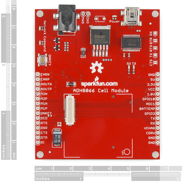
If you're not going to use the USB interface, you should unsolder the TX and RX jumpers to disconnect them from the FTDI chip. Then you can connect TX and RX to your own 8051 system.
You're on the right track, good luck with your project and let us know if you have further questions.
I think I may be at a similar stage in my project to #424122. I've been having fun with the ADH8066 mounted on the evaluation module by using the USB and sending AT commands from hyper-terminal. I think I'm now ready to try and move on to providing commands from my uC (PIXAXE 20X2). Are you saying here that I need to remove the solder jumpers from the Tx & Rx pads adjacent to the FT232 chip. If I do this then I can use the pins labelled Tx & Rx (10 & 11 down right hand side)?
That's correct. Technically you only need to disable the line from the FTDI to the cell module, labeled RX on the board, to prevent bus contention (two sources driving the line at the same time, which causes the data to be garbled). But honestly TX and RX directions are confusing enough that you're better off disabling both of them.
@ MikeGrusin : Thanks for the prompt reply. I don't intend to connect the eval board with a PC using USB,rather i want to connect it with the Micro controller directly. Could I use the Vcc pin to power up the board by connecting it to an output of an external regulator or only the 12V DC adapter should be used to power up the board? Just like in SM5100B eval board, are there any jumpers which must be cleared to use this eval board directly connected to a Micro controller?
The Rx, Tx pins in Evaluation board correspond to pins for either UART0 or UART1 ? What is the need for pins 5V, 3.3V and 1.8 V? I could not find the description for these pins in application notes nor in the datasheet.
Take a look at the schematic (which is in Acrobat PDF format) if you haven't yet. It shows that TX and RX are port 0, 3.3V and 5V come from the FTDI / USB port, and 1.8V comes from the ADH8066 module itself.
Is there an eagle part made for that ADH8066 connector?
it's in the eagle files http://goo.gl/7KrVr Though it is called a hirose DF12-50 if you wanted to look it up somewhere else.
Does this eval board come with antenna and wall wart?
No-the evaluation board comes just as itself. You will need to purchase the ADH8066 module, antenna, and wall wart separately. Check the related products below-all the items are listed there.
Note you should remeber to attach the antenna before plugging the module into the board, since the connector is on the lower side. Also note that this baby talks by default at 115200 and does not seem to autobaud, so use this baud rate if you are not seeing expected feedback.
I can't seem to get any info on connecting the SIM holder to this board. Any ideas?
The SIM holder is already connected to the ADH8066 module itself, so there is no need to connect a SIM holder to the evaluation board.
Does this come with a wall adapter power supply?
No, this only comes with the evaluation board itself. However, you can find the supply in the related products for purchase.
The ADH8066 draws up to 2A; the suggested power supplies say they give 600-650mA. Will these really be able to power the module properly?
What I'm seeing says that the module only draws max 350mA. But regardless, 600mA @ 12V = 7.2 watts of power. The module runs at 3.3V, max 350mA = 1.2 watts. You can't compare milliamps when the voltages are different. You have plenty of power with that adapter.
the "Firmware Update" link is broken... Is there any firmware update to apply to ADH8066 module ?
Has anyone been able to open the Eagle files? My computer is telling me "Invalid data in file...." Also, the schematic link above is missing a page... Any ideas?
The files all seem to be working on this end. Have you updated Eagle recently?
That connector must be one hell of a pick & place task.
Perhaps the connector comes with a pnp cap attached.