- Home
- Relay Control PCB

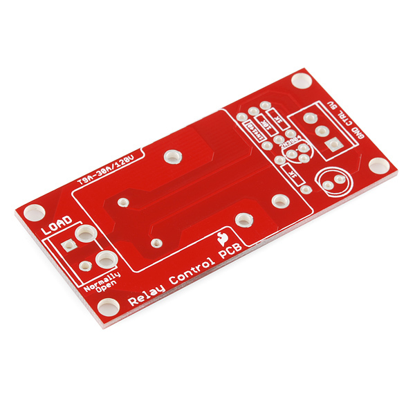
Relay Control PCB
Based on the Controllable Power Outlet Tutorial, this is the bare PCB that allow you to switch high voltages with a simple 0 to 5V GPIO on any microcontroller.
****Note:****This is only the bare PCB. You must buy the through-hole components and solder them to the PCB. The necessary through-hole components can be found in the parts wishlist below!
Note: Although we have revised this PCB to provide better isolation for the high voltage traces, this board and its parts are really meant for someone with some experience. If you're uncomfortable soldering or dealing with high voltage, please checkout the PowerSwitch Tail II. The PowerSwitch Tail II is fully enclosed making it a lot safer.
Relay Control PCB Product Help and Resources
Core Skill: Soldering
This skill defines how difficult the soldering is on a particular product. It might be a couple simple solder joints, or require special reflow tools.
Skill Level: Rookie - The number of pins increases, and you will have to determine polarity of components and some of the components might be a bit trickier or close together. You might need solder wick or flux.
See all skill levels
Comments
Looking for answers to technical questions?
We welcome your comments and suggestions below. However, if you are looking for solutions to technical questions please see our Technical Assistance page.
Customer Reviews
No reviews yet.
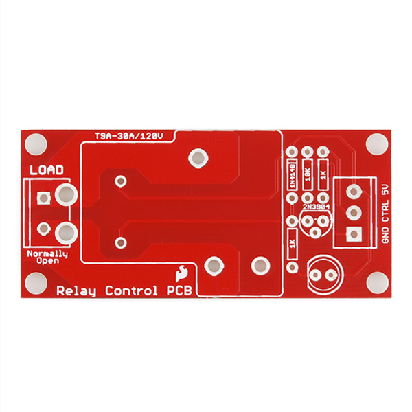
I'm curious as to why the PCB was designed to have the coil pins close to the high voltage terminals? Turning the relay 180 degrees would allow for much bigger traces in the same form factor. Also, there should really be stitching vias between the top and bottom high-current traces for better heat transfer.
I completely agree. Also, rotating it 180° would allow the NC contact to be broken out to the terminal strip. It seems silly to have a breakout board for an SPDT relay, but treat it like an SPST(NO) relay. They did say a final design is coming, so hopefully these enhancements will be considered.
Can you fix the link to the Parts Wishlist?
The Parts Wishlist link is bogus. Can you please provide a valid parts list link for this? I can see some of the parts to the right, but not all. More specifically, what LED is recommended and what wattage for the 2 1K and 1 10K resistors? I think I'm fine otherwise. Thanks!
Sorry about that, here's the correct link. The resistors and LED are on the logic side so the wattage is not critical.
The pad isolation on the high current pins for the relay and terminal block isn't ideal, sure it makes it a little easier to solder since you don't have a large trace acting as a heatsink (a good quality soldering iron will have no trouble) but if you pull too much current through the traces, they will be the first place to melt.
When mounting this board, use nylon screws. The screw heads come way too close to the high voltage traces and could electrify your enclosure.
The issues with this board were commented on at some length on the kit page for this board.
http://www.sparkfun.com/products/11042
Looks like ver 1.7 will have the relay turned 180 degrees for HV/LV separation on the relay.
EDIT: Updated wishlist is in the comment from MikeGrusin