- Home
- Product Categories
- GPS
- GPS Module - Copernicus II DIP (12 Channel)

GPS Module - Copernicus II DIP (12 Channel)
Replacement:GPS-11858. We've released a new rev of this GPS module that fixes a few silkscreen errors and adds a jumper between the VCC and XSTBY pins. Go check it out! This page is for reference only.
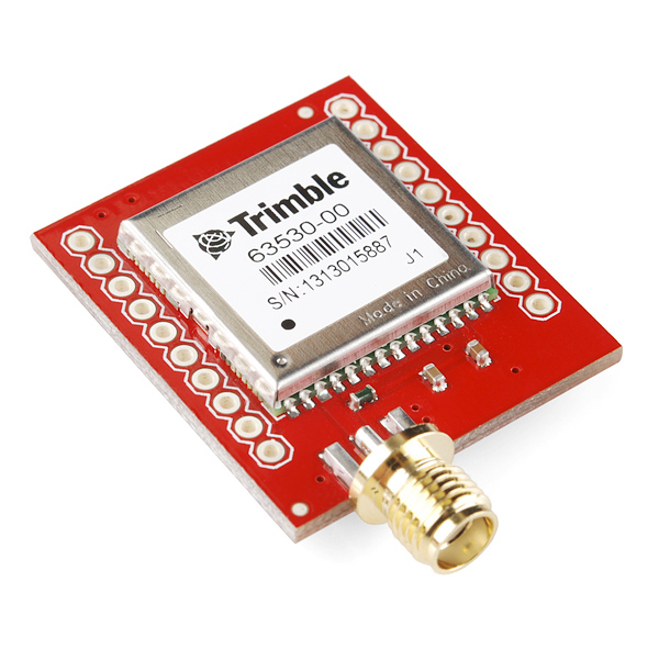
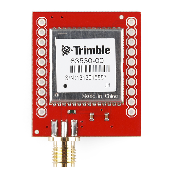
The Copernicus II is a great new GPS receiver from Trimble, but the SMD module prohibits immediate gratification. This DIP allows the customer to gain direct access to the pins on the SMD module. Simply provide 2.7 - 3.3VDC. The Copernicus II DIP breakout has an impedance-matched, end-launch, standard SMA connector that will mate with our SMA GPS antennas listed below.
This revision of the board does away with the pin-headers so that you can decide whether or not you want to solder pins to the board.
Check out our GPS buying guide!
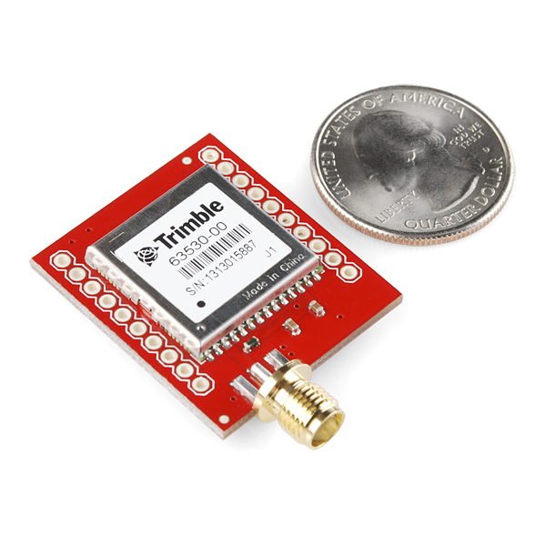
- 1.1 x 1.25"
- 0.9" between pins (bread board friendly)
**Replaces: **GPS-10923
GPS Module - Copernicus II DIP (12 Channel) Product Help and Resources
Copernicus II Hookup Guide
December 18, 2013
A guide for how to get started with the Copernicus II GPS module.
Core Skill: Soldering
This skill defines how difficult the soldering is on a particular product. It might be a couple simple solder joints, or require special reflow tools.
Skill Level: Noob - Some basic soldering is required, but it is limited to a just a few pins, basic through-hole soldering, and couple (if any) polarized components. A basic soldering iron is all you should need.
See all skill levels
Core Skill: Programming
If a board needs code or communicates somehow, you're going to need to know how to program or interface with it. The programming skill is all about communication and code.
Skill Level: Rookie - You will need a better fundamental understand of what code is, and how it works. You will be using beginner-level software and development tools like Arduino. You will be dealing directly with code, but numerous examples and libraries are available. Sensors or shields will communicate with serial or TTL.
See all skill levels
Core Skill: Electrical Prototyping
If it requires power, you need to know how much, what all the pins do, and how to hook it up. You may need to reference datasheets, schematics, and know the ins and outs of electronics.
Skill Level: Competent - You will be required to reference a datasheet or schematic to know how to use a component. Your knowledge of a datasheet will only require basic features like power requirements, pinouts, or communications type. Also, you may need a power supply that?s greater than 12V or more than 1A worth of current.
See all skill levels
Comments
Looking for answers to technical questions?
We welcome your comments and suggestions below. However, if you are looking for solutions to technical questions please see our Technical Assistance page.
Customer Reviews
No reviews yet.
Nate, very nice. But for what it's worth... ...did you try to optimize that antenna trace, or did you just figure it was so short it didn't matter? I notice you hung your inductor off a bit, instead of planting its tail on the main trace as is best practice (the hanging off part becomes part of the antenna).
You can download AppCAD for free and tweak that antenna trace for better performance, too. For instance, if the board thickness is 0.062", dielectric constant Er=4 (depends on material your fab uses), trace width=0.05", and copper is 1oz (0.0014" thick) then the resulting impedance of that microstrip at 1.575 GHz is about 80 ohms. The goal is 50 ohms, so you're squandering signal on a tiny 0.1" long trace... I'm just saying, shame to waste it. Again, for what it's worth. I'm no RF engineer, though I've forced myself to learn as much as I can for an upcoming GPS product.
It looks to me that the module uses a grounded coplanar wave guide and not a microstrip. If you re-run your calculation with a 50 mil trace and 10 mil clearance between signal trace and ground you should get approximately 50 ohms. http://i.imgur.com/sEpKPAK.png
I checked the Eagle files. This module is using a grounded co-planar wave guide but "S" (the spacing between the signal trace and the top-layer ground) is 12 mil instead of 10. This works out to an impedance of 52.8 Ohms. It would have been better if the spacing was 10 mil, but still a LOT better than 70 - 80 Ohms!
Well said
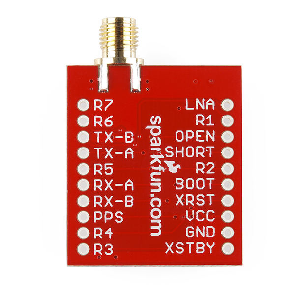
The pinout in the data sheet appears to be different from the schematic and the markings on the breakout. Which is correct? Or am I misreading things (quite possible): - The point that says R1 is connected to pin 6 in the schematic, which the manual says is VBat - The point that says BOOT is connected to pin 10, which the manual claims is reserved
Has no one else noticed this? Why is Sparkfun not responding?
Sorry about that! We try to keep up with the comments but sometimes some fall through the cracks. It looks like this is simply a labeling error. On the original Copernicus module, pin 6 was a reserved pin. I can't find any record about where the BOOT pin label came from. Regardless, for this module, pin 6 is actually VBAT and pin 10 is Reserved. Sorry for the confusion. We will get this updated as soon as possible.
Issues with output. I have setup the GPS Module based on the tutorial but I am not receiving data as expected. It will continuously show a single position. example output $GPGGA,,5230.60994,N,01319.66004,E,7,00,,,,,,,*52, UTC Time missing? I am i missing a pin that needs to be set to high. Please advise
I recently ordered one of these, and it came with a female RP-SMA connector. The description however says it comes with a standard SMA connector. This is very frustrating as I now have to buy an adaptor(WRL-09232) for it in order to be able to use the antenna. Even the picture above shows a standard SMA connector. Ugh!
Hey just to be fair, Sparkfun replaced the part very promptly.
An interesting module. Specs say it (along with uBlox devices) should work well for stratospheric balloons. It also has (again like the uBlox) a high dynamic mode, making it useful for rocket projects.
Does this module work above 60k ft, for near space projects?
Looks like it does: http://www.sparkfun.com/tutorials/361
...doesn't seem like the best GPS for the job though.
Did you mean 0.1" between pins in the dimensions section above? Hopefully there's not nearly an inch between pins, or is that the spacing between the headers? Thanks! :-)
Yes, it looks like the 0.9" means between the two rows. On a typical breadboard, it should straddle the 0.3" channel and still leave 1 of the 5 holes uncovered for each pin.