- Home
- Motor Driver 2.5A MC33926

Motor Driver 2.5A MC33926
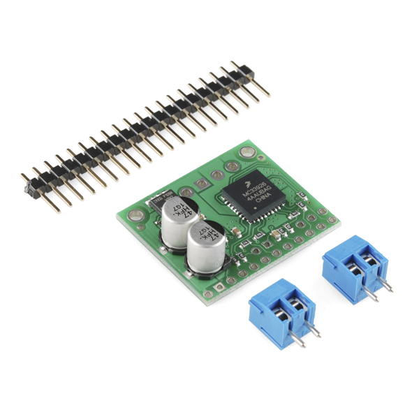
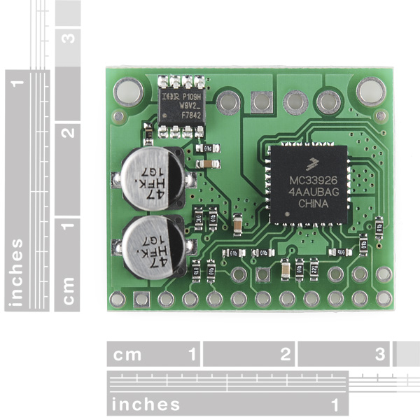
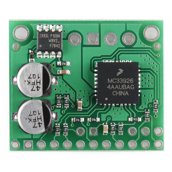
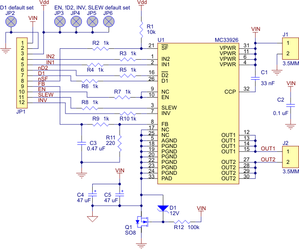
These compact motor drivers based on the Freescale Semiconductor MC33926 motor driver integrated circuit from Pololu are an easy way to connect a motor running from 5 to 28 V and drawing up to 5 A (peak) to your project. The board incorporates all of the components of the typical application diagram on page 25 of the MC33926 datasheet, plus motor-direction LEDs and a FET for reverse battery protection. All you need to add is a microcontroller or other control circuit to turn the H-Bridge on and off.
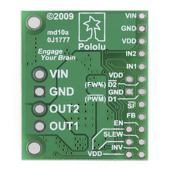
The enable (EN) pin does not have a pull-up resistor, so you must pull it to +5 V in order to wake the chip from sleep mode. The fault-status (FS, active low) output pin may be left disconnected if you do not want to monitor the fault conditions of the motor driver; if you do connect it you must use an external pull-up resistor to pull the line high. IN1 and IN2 control the direction of the motor, and D2 can be PWMed to control the motor?s speed. D2 is the ?not disabled? line: it disables the motor driver when it is driven low (another way to think of it is it enables the motor driver when driven high). Whenever D1 or D2 disable the motor driver, the FS pin will be driven low. The feedback (FB) pin outputs a voltage proportional to the H-Bridge high-side current, providing approximately 0.59 volts per amp of output current.
The MC33926 motor driver carrier PCB comes with two 47 uF, 35 V surface-mounted capacitors and holes for installing an additional through-hole capacitor. This third capacitor can be added in conjunction with the two surface-mount capacitors to further limit disturbances on the main power line, or it can be added in place of the two surface-mount capacitors to allow the MC33926 motor driver carrier to function at high voltages.
The MC33926 motor driver used on the carrier board has a maximum current rating of 5 A continuous. However, the chip by itself will overheat at lower currents. The actual current you can deliver will depend on how well you can keep the motor driver cool. The carrier?s printed circuit board is designed to draw heat out of the motor driver chip, but performance can be improved by adding a heat sink. (note: the entire PCB can get very hot long before the chip overheats, so be careful not to burn yourself).
Unlike other H-Bridges, the MC33926 has a feature that allows it to gracefully reduce current as the current exceeds 5 A or as the chip temperature approaches its limit. This means that if you push the chip close to its limit, you will see less power to the motor, but it might allow you to avoid a complete shutdown.
Replaces:ROB-08907
- 1 motor channel
- 5 to 28VDC operating voltage
- 2.5A continuous output current
- 5A peak output current
- 0.59 V per A current sense
- 20kHz PWM frequency
- Reverse voltage protection
- 1.03" x 1.35"
Motor Driver 2.5A MC33926 Product Help and Resources
Core Skill: Soldering
This skill defines how difficult the soldering is on a particular product. It might be a couple simple solder joints, or require special reflow tools.
Skill Level: Noob - Some basic soldering is required, but it is limited to a just a few pins, basic through-hole soldering, and couple (if any) polarized components. A basic soldering iron is all you should need.
See all skill levels
Core Skill: Robotics
This skill concerns mechanical and robotics knowledge. You may need to know how mechanical parts interact, how motors work, or how to use motor drivers and controllers.
Skill Level: Rookie - You will be required to know some basics about motors, basic motor drivers and how simple robotic motion can be accomplished.
See all skill levels
Core Skill: DIY
Whether it's for assembling a kit, hacking an enclosure, or creating your own parts; the DIY skill is all about knowing how to use tools and the techniques associated with them.
Skill Level: Noob - Basic assembly is required. You may need to provide your own basic tools like a screwdriver, hammer or scissors. Power tools or custom parts are not required. Instructions will be included and easy to follow. Sewing may be required, but only with included patterns.
See all skill levels
Core Skill: Programming
If a board needs code or communicates somehow, you're going to need to know how to program or interface with it. The programming skill is all about communication and code.
Skill Level: Rookie - You will need a better fundamental understand of what code is, and how it works. You will be using beginner-level software and development tools like Arduino. You will be dealing directly with code, but numerous examples and libraries are available. Sensors or shields will communicate with serial or TTL.
See all skill levels
Core Skill: Electrical Prototyping
If it requires power, you need to know how much, what all the pins do, and how to hook it up. You may need to reference datasheets, schematics, and know the ins and outs of electronics.
Skill Level: Competent - You will be required to reference a datasheet or schematic to know how to use a component. Your knowledge of a datasheet will only require basic features like power requirements, pinouts, or communications type. Also, you may need a power supply that?s greater than 12V or more than 1A worth of current.
See all skill levels
Comments
Looking for answers to technical questions?
We welcome your comments and suggestions below. However, if you are looking for solutions to technical questions please see our Technical Assistance page.
Customer Reviews
No reviews yet.
I'm not sure if this is the correct place to post this but anyone use the nD2 pin to PWM the driver to control speed with the arduino? I am attempting to use the analogWrite function off pin 10 of the UNO to slow the motor but any value below 255 doesn't turn the motor at all.
In a typical application, five I/O lines are used to connect the motor driver to a microcontroller: the two input lines, IN1 and IN2, for direction control, one of the disable lines, D1 or D2, for PWM speed control, the status flag, SF, for monitoring motor driver errors, and the current sense output, FB, for monitoring motor current draw (connected to an analog-to-digital converter input). The control lines can be reduced to two pins if PWM signals are applied directly to the two input pins with both disable pins held inactive. A two-pin interface can also be achieved using one of the disable lines for PWM speed control and the INV input for direction control with IN1 and IN2 held at different values (i.e. one set HIGH and the other set LOW). In each of these cases, the other unused lines must be set to enable proper operation. For example, if D2 is used for the PWM input (as is typically the case), D1 must be held low to prevent it from disabling the motor driver.
The link above for the data sheet actually goes to the MC33887 chip, not the MC33926 -- you may want to correct that when you get the chance. They do have a few differences.