- Home
- Product Categories
- SparkFun
- ATmega128RFA1 Development Board

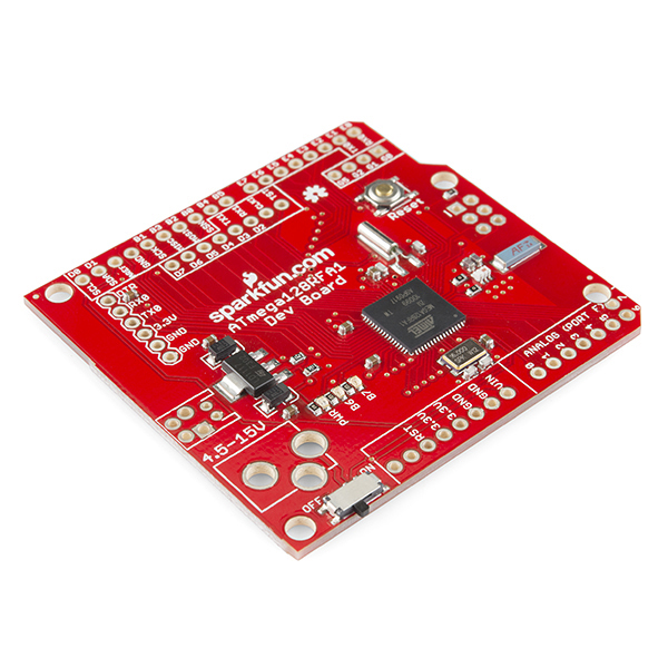
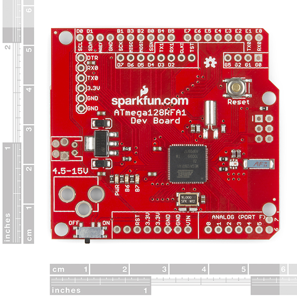
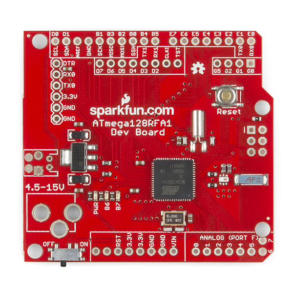
ATmega128RFA1 Development Board
The ATmega128RFA1 is a portmanteau of sorts – two separate components combined to form one device; half microcontroller, half RF transciever. ATmega128RFA1 is an IEEE 802.15.4 compliant single-chip, combining the industry- leading AVR microcontroller and best-in-class 2.4GHz RF transceiver providing industry's highest RF performance for single-chip devices, with a link budget of 103.5dBm.
The ATmega128RFA1 features Wake-on Radio, 32-bit MAC symbol counter, temperature sensor, automatic transmission modes, 128-bit AES crypto engine, true random number generator, high data rate modes, and antenna diversity support.
By looking at the ATmega128RFA1 Development Board you can see that we have changed the overall shape of the PCB to fit the Arduino form factor. We have also removed the SMD DC barrel jack and instead given you space to add a PTH DC barrel jack, JST connector (or screw terminal), and FTDI input. It includes an onboard 3.3V regulator and chip antenna. The board can be powered with either a 5V or a 9V wall wart.
- Schematic
- Eagle Files
- Datasheet (ATmega128RFA1)
- Hookup Guide
- GitHub
ATmega128RFA1 Development Board Product Help and Resources
Core Skill: Soldering
This skill defines how difficult the soldering is on a particular product. It might be a couple simple solder joints, or require special reflow tools.
Skill Level: Noob - Some basic soldering is required, but it is limited to a just a few pins, basic through-hole soldering, and couple (if any) polarized components. A basic soldering iron is all you should need.
See all skill levels
Core Skill: Programming
If a board needs code or communicates somehow, you're going to need to know how to program or interface with it. The programming skill is all about communication and code.
Skill Level: Rookie - You will need a better fundamental understand of what code is, and how it works. You will be using beginner-level software and development tools like Arduino. You will be dealing directly with code, but numerous examples and libraries are available. Sensors or shields will communicate with serial or TTL.
See all skill levels
Core Skill: Electrical Prototyping
If it requires power, you need to know how much, what all the pins do, and how to hook it up. You may need to reference datasheets, schematics, and know the ins and outs of electronics.
Skill Level: Rookie - You may be required to know a bit more about the component, such as orientation, or how to hook it up, in addition to power requirements. You will need to understand polarized components.
See all skill levels
Comments
Looking for answers to technical questions?
We welcome your comments and suggestions below. However, if you are looking for solutions to technical questions please see our Technical Assistance page.
Customer Reviews
No reviews yet.
can I make it work with batteries?
Can this board be used with the Arduino IDE?
I followed the "Hookup Guide" link above and found: "ATmegaBOOT bootloader pre-programmed (making it programmable with an FTDI Basic and the Arduino IDE)"
Does it works with TinyOS?
i have problem with the board, i can't program with arduino IDE 1.6.0, i use the tutorial and the arduino IDE say ERRO you need plataform.txt, i need help!
Arduino 1.6.0 uses a different file structure than 1.0.x, we are still in the process of updating things. Try using 1.0.6 or email techsupport@sparkfun.com and they should be able to help you get it working in 1.6.0.
Hi, We have an ATMEGA 128RF A1 development board from spark fun https://www.sparkfun.com/products/11197 as instructed from the Atmel website, we downloaded the bit-cloud for mega and burned the pre-compiled hex into the chip using ISP. Then we changed the fuse setting for the oscillator to EXTCLOCK_6CK_0MS that bricked the chip. We assure that we have not disabled the ISP and or the Reset function.
Is there any other solution for this problem? We have lost 2 RFA1 chips now.
Sorry, we didn't see this sooner. Please email techsupport@sparkfun.com and they can look into this for you.
(found it right now ... maybe to late) The setting EXTCLOCK_6CK_0MS expects a clock on the pin CLKI. Any square wave should be fine.
Keep your eyes on SJ1 next to JP5 ... looks to me like a short (need to be open to apply a clock). With an external clock on CLKI your programmer should work immediately.
Choose one of the oscillators fuse-settings. Then the part is cured do not let the pin floating. Re-install the short or add a resistor if you plan to use pin CLKI.
Just a heads-up that starting with BitCloud 3.0.0, the Atmega128rfa1 is no longer supported. I am dead in the water in regards to getting a Zigbee PRO stack on this thing :-/
Could you provide the Bootloader? I prefer to use AVR ISP over the serial port programming but I have my other friends who do not prefer that (I don't use Arduino IDE). One option would be that I read the memory before I program it but I usually manage to loose the file.
Certainly. You can find the bootloader source and hex file here in the GitHub repo. Have fun!
I noticed on the datasheet that the chip is capable of Wake-on-radio. When I searched around(googled) I did not find another mention of how to achieve this capability. Does anyone know of some example code or an explanation that is centered around low power consumption or the WOR(wake on radio) functionality.
Does anybody know why the example code in the "Hookup Guide" won't compile correctly for me. I have Arduino 1.0.5 and the latest version of WinAVR. I have followed the tutorial verbatim and all has been well up until this point. The example code seems to be saved to the right locations and the Arduino IDE sees the ATMega128RFA1 dev board, but when the code is compiled it throws multiple errors mostly stating "this variable was not declared in this scope". I've researched and tried all the obvious fixes.
Did you select the ATMega128RFA1 board? I ran into the issue as well. I also had to place the board (128RFA1-DEV folder) in this directory -> C:\Program Files (x86)\Arduino\hardware. I tried the my docs route and the board would show up but would not work.
I ended up just uninstalling and reinstalling the entire Arduino IDE and made sure my file path was correct when I downloaded the BasicChat example. This did the trick and I got it to work, I think I had somehow created too many subfolders within the avr and the IDE didn't know where to look. Hope this helps for anyone who had the same issue.
I recently purchased 2 boards. And used the example code given in the hookup Guide for testing but I was not able to get a range more than 2 meters, while it is mentioned it can get a range up to 75 meters. Please help me, if i need to do anything else to increase the range..
Please can any one from the technical team help me up..
Email techsupport@sparkfun with a description of your full set up and they should be able to help you out further. Sorry for the delay in response!
Quick question... Has this board been run through the gauntlet to be FCC certified? I don't know if that is even necessary for this kind of product, and it would probably only matter for someone wanting to build these into a commerical home product, but IANAL.
Once someone builds it into a product, it becomes their problem to get it certified.
Ultimately, it's a radio module, just like, say, the XBee. Digi has pursued a course of modular certification for the XBee module as a selling point; it reduces cost and difficult for the end user. Since most of these boards are going into home-built devices, we don't feel the cost of pursuing modular approval is justified.
Yeah, I know that the cost of FCC certification would only make the price of such a product prohibitive considering the volume. I just wasn't sure what the exact legal issues were in a hobby / prototype product environment. I bet Atmel's "Explained" boards weren't run thought the FCC gauntlet either. Technically ANY device that contains RF energy (ALL computers!) would require such certification for class A or B environments, not just something that is actually a 'radio'.
I'd second the request to make a version of this board with the atmega256RFR2 chip. It is a pin for pin replacement, and given it's lower in cost than the atmega1284p would make a killer of an Arduino clone WITHOUT the radio! OMG 256k flash, 32K sram and 8k eeprom! Tell you what, sell me a bare board and I'll do it myself! BTW there is a new board out there called Pinoccio that uses this chip. Not available yet, but at the same price it looks interesting.
What is the resolution of the PHY_RSSI Signal ?
Since you were designing a new board anyway, is there any particular reason why you're using this very old chip, rather than some of the newer, slightly more useful models, such as the ATmega128RFR2 or 256RFR2? They're drop in replacements that would allow for a much more flexible board in terms of potential uses.
Atmel's own evaluation board based on the much better ATmega256RFR2 is only $39, available directly from Atmel. It also includes both a ceramic antenna and an SMA connector for an external antenna, as well as an onboard USB connector with embedded debugger allowing for much easier development work in Ateml Studio, and onboard reset and programming buttons.
Hmm. Tried to answer this one myself and it seems like you're familiar with the products in question...
Any advantage of this board (or the eval board you mentioned) over the Freakduino?
http://www.freaklabsstore.com/index.php?main_page=product_info&cPath=22&products_id=204
It's based on the AT86RF231 radio with a ATMEGA328 - I assume this design (being single-chip) might have better power characteristics? Arduino compatibility (especially with all the shields I have kicking around) is a big plus for me.
This one has some of the features people are asking for: http://logos-electro.com/zigduino/
OUCH! $15 MORE expensive than the board it replaces! At this price I'd have expected an external antenna socket for a 'rubber duckie' along with a standard AVR Jtag connector.
It's cheaper; the original price on the old board was $54.95. The $34.95 price is to clear out the old stock.
http://web.archive.org/web/20130502155916/https://www.sparkfun.com/products/9734 what the page looked like a couple months ago.