- Home
- Product Categories
- Sensors
- Fingerprint Scanner - 5V TTL (GT-511C1)

Fingerprint Scanner - 5V TTL (GT-511C1)
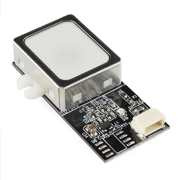
Fingerprint scanners are awesome. Why use a key when you have one right at the tip of your finger? Unfortunately, they're usually unreliable or difficult to implement. Well not anymore! We've found this great fingerprint module from ADH-Tech that communicates over TTL Serial so you can easily embed it into your next project.
The module itself does all of the heavy lifting behind reading and identifying the fingerprints with an on-board optical sensor and 32-bit CPU. All you need to do is send it simple commands. To get started, just register each fingerprint that you want to store by sending the corresponding command and pressing your finger against the reader three times. The fingerprint scanner can store different fingerprints and the database of prints can even be downloaded from the unit and distributed to other modules. As well as the fingerprint "template," the analyzed version of the print, you can also retrieve the image of a fingerprint and even pull raw images from the optical sensor!
This is the more economical version of the GT-511 which has a decreased memory capacity (compared to the GT-511C3). The module can only store up to 20 different fingerprints and is only capable of 30° fingerprint recognition. If you are on a budget and need only a small number of fingerprints stored, this is the perfect option for you!
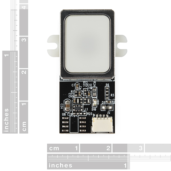
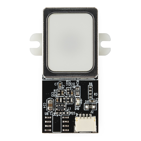
The module is small and easy to mount using two mounting tabs on the side of the sensor. The on-board JST-SH connector has four signals: Vcc, GND, Tx, Rx. A compatible JST-SH pigtail can be found in the related items below. Demo software for PC is available in the documents below, simply connect the module to your computer using an FTDI Breakout and start the software to read fingerprints!
Note: The module does not come with a cable, check below for an appropriate one.
- High-Speed, High-Accuracy Fingerprint Identification using the SmackFinger 3.0 Algorithm
- Download Fingerprint Images from the Device
- Read and Write Fingerprint Templates and Databases
- Simple UART protocol (Default 9600 baud)
Capable of 1:1 Verification and 1:N Identification
37 x 17 x 9.5 mm
- Datasheet
- Demo Software
- Garage Door Opener Tutorial (Instructables)
- GitHub (Example Code)
Fingerprint Scanner - 5V TTL (GT-511C1) Product Help and Resources
Core Skill: Programming
If a board needs code or communicates somehow, you're going to need to know how to program or interface with it. The programming skill is all about communication and code.
Skill Level: Rookie - You will need a better fundamental understand of what code is, and how it works. You will be using beginner-level software and development tools like Arduino. You will be dealing directly with code, but numerous examples and libraries are available. Sensors or shields will communicate with serial or TTL.
See all skill levels
Core Skill: Electrical Prototyping
If it requires power, you need to know how much, what all the pins do, and how to hook it up. You may need to reference datasheets, schematics, and know the ins and outs of electronics.
Skill Level: Noob - You don't need to reference a datasheet, but you will need to know basic power requirements.
See all skill levels
Comments
Looking for answers to technical questions?
We welcome your comments and suggestions below. However, if you are looking for solutions to technical questions please see our Technical Assistance page.
Customer Reviews
No reviews yet.
Does anybody knows if this device can read 2d printed fingerprints? If not, does anybody knows of any one? If it can read both real fingerprint and 2d images the better!! Thanks!
Fingerprint Scanner - 5V TTL GT511-C1 [RETIRED]
We don't sell the cable with the GT-511C1 fingerprint scanner https://www.sparkfun.com/products/11836. You would need to get the 4 wire JST SH jumper cable separately https://www.sparkfun.com/products/10359. There is more than one way to create a connection between the fingerprint scanner and your system. For a more secure connection with the thin gauged wire, I recommend modifying the cable. Any loose connections can have issues powering the sensor and sending reliable data. Check below for more information:
Serial UART Connection w/ 4 Wire JST SH Cable
For a secure connection, I recommend soldering the ends of the wire to some header pins [like these https://www.sparkfun.com/products/116 ] so that the connection is not loose when inserting it into a standard female header sockets on an FTDI or the RedBoard/Arduino Uno. This will provide easy access to the small 4-pin JST-SH connector that is on the fingerprint scanner.
After checking the connections of the scanner in the datasheet, I soldered connections from the JST -SH connector labeled J2 from the scanner to the header pins. I used some heat shrink in order to use it with the FTDI to reinforce the solder joint. As a note, make sure to remove the JST-SH SMD connector that is on the 4-wire jumper wire assembly. This is the same connector that is on the fingerprint scanner. You should be able to remove the connector easily with your hands without cutting any of the assembly off. The connections with the header pins are based on the footprint of the 3.3V FTDI basic breakout https://www.sparkfun.com/products/9873 w/ a mini-B cable https://www.sparkfun.com/products/11301:
Note: If you were using the JST-SH cable, you would be wiring the black wire to pin 1 (next to the notch indicating the polarity on the fingerprint scanner to the Rx pin of your FTDI,For an example of the modified cable assembly, I suggest checking out the images from our Google drive:
https://drive.google.com/open?id=0B0jwgLkjMWzDfnktUkt5ekQxQi1TcXk3QnhMN2J0Q3VXT2Y4NXRZdG9wa05EemZjY0dCazg
Demo Software Development Kit (SDK) w/ a FTDI
For basic operation with the demo software, I recommend checking out the demo software that is linked in the documents section of the product page. Each demo software is unique to that version of the fingerprint scanner and it will not work with the other versions. After connecting the fingerprint scanner to the FTDI, I was able to utilize all of the features as stated in the datasheet. These features in the demo software are based on the protocol commands.
To operate on a computer using the SDK, just open the SDK_DEMO.exe executable, select the COM port that the FTDI enumerated to from the serial port number's drop down menu, and click on the Open button. You would need to enroll your finger 3 times for the ID before the scanner can save it as a template.
Demo Software Development Kit (SDK) w/ an Arduino Microcontroller
Testing this with an Arduino Uno and the serial passthrough code https://learn.sparkfun.com/tutorials/xbee-shield-hookup-guide#example-communication-test, I was able to connect to the SDK demo software. This might be another alternative if you not have a 3.3V FTDI to connect to your fingerprint scanner. You just need to make sure that have the correct logic level translation, are selecting a COM port that is lower than COM10 (the lower COM number, the better; COM3 is the lowest that you can use), and selecting a baud rate of 9600 in the SDK demo software.
Example Code for Arduino If you were using a microcontroller with the fingerprint scanner, you would need to write code based off of the demo software and the protocol commands. Luckily, there was someone in the community that wrote some example code to blink the blue LED, enroll, and identify the fingerprint that was saved in a template. The library is limited in the functionality compared to the SDK demo software but is sufficient enough for basic use. It is posted in a GitHub Repository https://github.com/sparkfun/Fingerprint_Scanner-TTL.This code works with the GT511C3, GT511C1, and GT511C1R. This code is incomplete and would require more code to utilize all the features of the fingerprint scanner like in the SDK. Here are the connections that you would need to make using a bi-directional logic level converter https://www.sparkfun.com/products/12009:
Software Serial with the Arduino Mega 2560 The demo code was designed for the Atmega328P on the Arduino Uno. If you were using it with an Arduino Mega2560, you would need to re-configure the software serial pin definitions. The reason why is because not all the pins on the Arduino Mega can support change interrupts for a serial Rx pin as stated in the limitations => https://www.arduino.cc/en/Reference/SoftwareSerial . Just change this section of code on line 18:
to
Direct USB Connection w/ USB Port
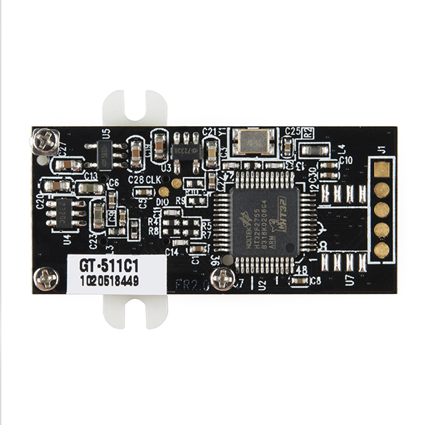
Demo Software Development Kit (SDK) To connect the GT-511C1 fingerprint scanner with the demo software and your computer's USB port, you can connect the pins on the back of the board labeled with J1 directly to the USB port of your computer. I used a micro-B breakout board and a USB micro-B to A cable. Here are the connections that you would need to make:
By connecting to your computer, it will show up as a USB Mass Storage Device on My Computer ("Gingy Disk" is the name of the Removable Storage Device).
Note: Certain USB Cables have D- as green and D+ as white. For an example of making your cable assembly, check out the images in our Google Drive. The images provided shows the non-standard colors wired up for the data lines with a USB connector. If the fingerprint scanner is not recognized by your computer in the device manager or there is a warning message, try reversing the data pins on the fingerprint scanner and it should enumerate properly.
https://drive.google.com/open?id=0B0jwgLkjMWzDSnVtc2tVMllYS1E
Troubleshooting
Scanner Not Recognizing your Fingers? There have been issues trying to enroll with the Arduino example code. This is usually due to fingers being dry and not having good contact on the scanner. The timing of your finger on the scanner is a little tricky too. I had to try enrolling a few times before it was able to enroll or identify my finger. This is common with any fingerprint scanner like the one that is on my smartphone. Try re-enrolling your finger.
Hardware Connections: Loose Connections Make sure that there are no loose connections. The last thing to check is the connection between your scanner and Arduino. Each of the fingerprint scanners use the same command protocols so the Arduino example code in the Instructables tutorial can be used for any of the scanners.
The "demo software" link (GT-511C3_SDK_20130410.zip) is for the C3 model and does not work with the C1 model (at least not with the one I got). The software associated with the C1 model is here, but this version of SDK_DEMO.exe doesn't have an option for a serial connection mode so you have to hook up using USB or roll your own serial interface.
Also, the C1 serial connection does not support the image download and template management commands. But it does all the basic commands required for fingerprint identification (enrollment, LED control, capture, identification, etc). The image upload commands only work when using a USB connection.
It might be my imagination, or maybe individual device variances (I only tried one of each), but the C3 model seems a little better at enrollment and fingerprint identification. So for best results, and a demo program that works in serial mode, and all the features like image download, get the C3 model and make sure you're using the correct SDK_DEMO.exe file.
Mmm, maybe a problem with the firmware. I am coding a driver using VC2010 and I have problems with image download also, however I can perform the command "GetTemplate" but this command return the only the firmware version. They should provides a fixed firmware
Finally got this working on arduino! I'll post some stuff when I've got a sketch working perfectly, but in the meantime here's what I did:
It's pretty rough, but I hope this helps someone who was struggling with this as much as I was.
If you're not familiar with some of this:
A byte stores 256 values. A word consists of 2 bytes, and a Dword consists of 4 bytes. The bytes to be sent here were represented in hexadecimal, which is base 16. A word can be split into 2 bytes to be sent. For example: 0x1234 is made up by the bytes 0x12 and 0x34. highByte(0x1234) = 0x12 and lowByte(0x1234) = 0x34.
Hope this helps!
I've built on your excellent start with an Arduino sketch which allows the scanner to be controlled from the Arduino IDE serial monitor using a Mega as a go between.
https://github.com/mlaws/GT-511C1_Mega
Man am I stuck on this! Using a Teensy 3 to communicate via serial to this fingerprint scanner, measuring 3.3V on it's UART line (Serial 3) and getting absolutely nothing on the serial monitor in the Arduino software. Thinking it was a problem with level conversion I then tried using an 2N7000 MOSFET to prevent high levels damaging the scanner, still no response. The puzzling thing is I'm not sure if the scanner is expecting 0 - 5V TTL values or 0 - 3.3V TTL, and the same goes for the Teensy (although when it runs off of the USB connection I'd assume the Vref is 5v?). I've connected the pins as if the JST SH's black wire is the Rx from the scanner, although they could be better colour co-ordinated! I'm completely stumped, any ideas guys??
Hi everyone, i have bought GT-511C1, the problem that the software didn't work with it, i can't choose the port for it, and i need the software urgently as i use it in my graduation project, so could anyone help me with this. or if any one know the preprocessing type that this sensor use.
Hi, were you able to ever get this to work??? I didnt and my graduation is 2 months away and my project progress is not looking good. if you did, can you please help me out, please :)
The sensor must be connected directly via USB. When USB connected, the scanner will populate on your computer as a mass storage device. Once the computer has registered the mass storage device, you will be able to connect to the software and begin registering your fingerprints.
Just connect the V+, V-, D+, and D- lines from a USB cable to the back of the scanner as shown explained below and launch the GT-511C1 software as normal.
The connection of the sensor from the back side with the USB connections starting from the pad near to (J1) and go down: 1 - Red. 2 - White. 3 - Green. 4 - Black.
Hope this helps,
I'm having a lot of trouble getting this to communicate with the software. I first tried using it with the 5V FTDI cable (and a 5k resistor) with no results. (And reading the comments, rsp has noted that it will not work over serial with any of the software) Also, it seems that Sparkfun has the wrong pinout. On this page it says Vcc, GND, Tx, Rx whereas the data sheet says Vcc, GND, Rx, Tx. Hopefully It didn't damage the device. Anyways, I tried it with different baud rates as well, because the video says 115200 and the site and datasheet say 9600. So I'm guessing the video was for the C3 model? I'm a little disappointed with the documentation here. I also tried a USB connection with the pins that rsp has given me: Pin 1 (square pad) = +5V (usually the red wire in a USB cable) Pin 2 = D- (white or yellow) Pin 3 = D+ (green) Pin 4 = Ground (black) Pin 5 = Shield (optional)
But that doesn't seem to work. Perhaps I need the right driver for it? When I plug it in, the light for the sensor blinks quickly and then the green status light flickers very dimly. The software doesn't recognize it, and my computer doesn't seem to recognize it either. :/
I'm hoping to get it working with the software first so I can better understand how to properly operate it, but if not, I'll just have to connect it to my arduino and play around with it from there.
Could you tell me what you did to resolve the dimly flickering green status light? I am having the same problem and I fear that I may have fried the board from playing around with it too much.
Hi. One of my students clicked on "update firmware" and sent the first ".bin" file he found ! Now one of my GT-511C1 is out of order. It's always recognized by my PC (such a disk), but can't dialog with the SDK_DEMO program. Is there a way to restore the firmware (I'm in USB mode) ? Thanks.
Would it be possible to get around the 20 fingerprint limit by this solution?
Let say we are going to store 10,000 fingerprint templates on central server. We also have 1,000 fingerprint scanners across the country that have access to this central database.
Will this scenario work for Enrolling a user? 1, Ask user for phone number 2, Exec Delete All 3, Exec Enroll 4, Set Database (to central server) 5, Intercept the Set Database to assign an additional column titled phone number (primary key)
Will this scenario work for verifying a user? 1, User enters phone number 2, Queries central database using phonenumber 3, Get Database (I am assuming the ID will need to be 1-20 so we'd need to modify the query above to strip phone number) 4, Exec Verify 5, User places finger on scanner, sensor verifies.
Logically this should work...has anyone tried this? If so, are you are you able to exec the HTTP query's quick enough for this process to be usable in a production environment?
Thanks in advance for anyone's input on this
It would be a little bit complex but yes. Watch the video and you see that you can save the bmp of the finger print and you can do scans. But the purpose of the fingerprint scanner is to use the algorithms on the device so bypassing those would kind of defeat the purpose. You would then just have a finger print camera. So yes but there would be some software customization to be done.
I have gt511c1 and I am connecting pins started with squared pin (suggested by Member #487587 and rsp) with the USB cable. When I connect it with pc it says "USB device not recognized". There is also no response on the demo software. I am using windows 7 64 bit.Is there any driver issue or something else? please let me know if somebody knows the problem Regards ahsan856jalal@gmail.com
Has anybody tried to download the fingerprint template from the reader? What format is it in? is it a set of raw 506 bytes that can be stored in an array of bytes?
Guys - common !! Upgrade your server !! I had to restart this video 5 times just to finish it - it kept stalling on me and going to error/failure !! Great video - but very frustrating !!
Hi everyone, I just bought GT-511C1 and i want to know if i can use it with an Arduino Uno and his UART port ?
I saw in GT-511C1 datasheet a lot of function like (Verify, verifytemplate etc...) can i use it with the arduino ? Is there a specific line to note at the beginning of the code ?
Please help me !
Hi i am new to this product. I am using the 511C2 version( i have no idea how have i ended up with a C2 version when on the site it says only C1 and C3), can anyone please help me with the coding part. I have connected it to my raspberry pi serially, and i want to communicate with it using the serial communication. However i want to know how should i be doing this communication. I will appreciate your help.
Hello everyone, I am working on my senior project and I was trying to connect this fingerprint scanner and arduino uno together. I also purchased the Jst sh jumper 4 such that they were able to connect, I am having issues with this. Can someone give me more insite if you guys are using it too. Thanks! much appreciated.
Hey guys. Do you send to Brazil? Thank you.
Yes, we send products to your beautiful country!
Sim, nós fazemos envio de produtos para o seu belo país!
Thank you for the answer. Just one thing more. Which Arduino should I use?
Has anyone had success with or tried using this to operate a relay?
Has anyone successfully hooked this unit up to a Mac or Linux machine via USB?
I've soldered the module directly into a USB cable using the test pads on the bottom and tested it using their windows software successfully. However I have not been able to figure out how to communicate with the module via Mac or Linux. Any information on how to do this would be a huge help!
Someone read "The Game" and is peackocking...
Does anyone know if this unit will work behind a piece of glass or clear acrylic? How about smoked acrylic? Trying to figure out ways to waterproof this!
Has anybody used this scanner with any PIC microcontroller? I'm thinking of using it for a finger print access control project.
I was... But it has really been a huge pain in the *ss... I can give you some sort of base code using pic 16F788/877A-18F4550/2550. Those are the ones I've tried and the module answered just great. The matter is: I wasn't able to process the string returned from the device, despite of knowing the answer string is perfect, I can't go beyond a mirror of the answer, but I haven't spent much more time focused on solve this. If you make it work it'd be awesome hahaha Saludos desde México
Building on the great work on FutureInventions, I have made a sketch for the Arduino Mega which acts as a link between the scanner and a computer.
Load the sketch onto the mega, open the serial port monitor in Arduino and send two letter/number commands to control the scanner.
github link
Are the 5 open pads on the end of the board connected to the JST connection? Can the be used in lieu of a JST cable?
Adafruit makes a fingerprint scanner that is somewhat pricier then this. both sensors seem identical spec wise. they've prepared an arduino library for it." https://github.com/adafruit/Adafruit-Fingerprint-Sensor-Library " just curious as to whether or not this could successfully be used with this one.
I want to hook this up with an Arduino. Is this what I need? https://www.sparkfun.com/products/8745
You can connect the UART transmit and receive lines directly to a 5V ATmega328 Arduino. The GT-511 transmit level is 3.3V (measured), which meets the '328 input requirement of 0.6*Vcc. The GT-511 receive pin looks like it's 5V tolerant, but they don't explicitly say that, so I'd put a 5K resistor in series just for extra safeness (this is the configuration I tested, and it works fine).
Thanks so much! Also, do you know if the pads on the back are the same pinout as the connector on the front of the device? (Plus a square pad, I'm assuming that's ground?)
The pads marked J1 are for a USB connection; the pinout is:
To use the SDK_DEMO.exe program over USB it must be the version for the C1 model, which is here.
Thank you very much!
arduino code?
Could you bring us some C++ or CCS demo code?? Because I haven't found any of it and I have had a really hard time trying to communicate with the device, even with the demo software, wich, in deed, does all of the functions about storage, templates, etc. But the functions that imply the fingerprint sensor itself (detect if the finger is pressed, enroll, identify or verify...) are really a pain for my brain, because hardly ever detects the finger. It almost every time goes "Timeout". Thanks
I wrote a library for VC++, you can read my blog http://fernandezajp.blogspot.com/2013/07/modulo-biometrico-gt-511c1.html is a windows console application uncomments some lines in the _tmain function in Console.cpp to test the module
I need to use this fingerprint scanners in several locations. but i need only one database for all scanners. is that possible?
Yes, you can if you use it along a micro controller; you should develop a library to manage it and provides this special feature
I'm looking for the same feature. I've been reading the manual and I'm not sure how should that be done. Wont the sensor force me to enroll the fingerprint for validation?
I just got one of these and realized that there's no connector cable. Does anyone know which one I need? I only see a 6 pin one on here.
It's likely to be PRT-10359. Edit >> confirmed, this is the correct connector.
Does anyone know if I could use this with an Arduino to identify fingerprints and then unlock a door if the fingerprint is known? Thanks
Does anyone know of a fingerprint reader like this which instead of matching live prints against stored "known" prints, just passes out some kind of fingerprint GUID or "checksum" for each fingerprint press? My problem is that I want to write software to keep track of more people than this module will hold, and I have no problem maintaining an external database of "fingerprint codes" but using this module, you have to keep all the known fingerprints stored in the module..
Kind of what I want is the same concept as a typical RFID reader, but for fingerprints.. A long, unique, but repeatable number for each print, to be fed to be via serial...
Correct me if I'm wrong: I understand, the 506 bytes template is only available once the third print was taken during enrollment. Then it can be downloaded by the enrollment ID. (Should look at the C++ demo code ... but I don't have any inclination right now ... sorry!)
If the template IS available after scanning the finger, it is probably what you are looking for. It must be some sort of 'summary' of the print - so to say. Then it would be enough to simply compare it with other templates in the database. Perhaps applying some tolerance. I would capture the same print and create a template several times. Then see the differences between the templates. This would give some idea regarding the tolerance/deviation. Perhaps it leads somewhere.
It seems one can download the picture of the captured print though.
I tried finding a 'fingerprint identification algorithm' 'for embedded systems' - none of them gave the actual algorithm ... maybe you are luckier or more patient ... pls tell us if you solved it. :)
I think that's what the 506 byte template is, which you can read using external software. I don't think it comes out exactly the same every time though, so you have to run some sort of matching algorithm yourself. The benefit of the ones stored inside the module is the module runs that matching algorithm for you.
Remember to flash every single fingerprint on the screen as your software does the search, CSI-style :-)
I think you're basically right, but the "some sort of matching algorithm" is the problem... I don't think it's documented as to what you can do with that data, other than to store it externally and import it into another fingerprint reader so users don't have to register on each device.
I believe I know who the OEM of this device is, because it pretty much matches up with a PC based device that I bought a couple years ago, and I bought the dev kit for it, and as you imply, there are proprietary DLLs that they provide to do the matching... Nothing that could be conveyed to an embedded situation.
Don't get me wrong - The device itself is awesome, and if my application would allow me to pre-load all the fingerprints in, it would be perfect. This would be a great device to build a home automation / security system, etc, but for the project I have in mind, this is a perfect round peg for my square hole..
Why does the website say 2 comments, but show none? We'll see if this one shows up.. I'll ask my question in a separate comment..
Showed up fine. They sometimes delete comments when they are not directly related and merely, say, administrative notices. In this case, according to the RSS, something was wrong with the price. ( Expect this comment, and possibly yours, to get zapped as well :) )