- Home
- Product Categories
- PTH ICs
- Dot/Bar Display Driver - LM3914 (Linear)

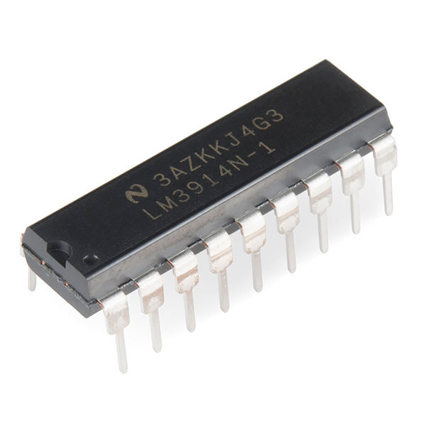
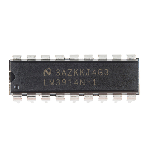
Dot/Bar Display Driver - LM3914 (Linear)
This is the LM3914 Dot/Bar display analog-controlled LED driver that uses an alinear output scale. With this driver all it takes is a single, analog signal to drive a string of 10+ LEDs, which can be configured into either bar mode (where all LEDs below a certain point turn on) or dot mode (with only a single LED on at a time). Hook them up properly, and you can create all sorts of nifty multi-LED displays.
The LM3914 is very easy to apply as an analog meter circuit. A 1.2V full-scale meter requires only 1 resistor and a single 3V to 15V supply in addition to the 10 display LEDs. If the 1 resistor is a pot, it becomes the LED brightness control. The simplified block diagram illustrates this extremely simple external circuitry.
- Drives LEDs, LCDs or Vacuum Fluorescents
- Bar or Dot Display Mode Externally Selectable
- Expandable to Displays of 100 Steps
- Internal Voltage Reference from 1.2V to 12V
- Operates with Single Supply of Less than 3V
- Outputs can Interface with TTL or CMOS Logic
- [Datasheet](http://cdn.sparkfun.com/datasheets/Components/General IC/lm3914.pdf)
- Hookup Guide
- Product Video
Dot/Bar Display Driver - LM3914 (Linear) Product Help and Resources
Dot/Bar Display Driver Hookup Guide
January 16, 2014
How to hook up the LM3914 or LM3916 to drive a 10-LED display with a lone analog signal.
Core Skill: Soldering
This skill defines how difficult the soldering is on a particular product. It might be a couple simple solder joints, or require special reflow tools.
Skill Level: Rookie - The number of pins increases, and you will have to determine polarity of components and some of the components might be a bit trickier or close together. You might need solder wick or flux.
See all skill levels
Core Skill: Programming
If a board needs code or communicates somehow, you're going to need to know how to program or interface with it. The programming skill is all about communication and code.
Skill Level: Rookie - You will need a better fundamental understand of what code is, and how it works. You will be using beginner-level software and development tools like Arduino. You will be dealing directly with code, but numerous examples and libraries are available. Sensors or shields will communicate with serial or TTL.
See all skill levels
Core Skill: Electrical Prototyping
If it requires power, you need to know how much, what all the pins do, and how to hook it up. You may need to reference datasheets, schematics, and know the ins and outs of electronics.
Skill Level: Competent - You will be required to reference a datasheet or schematic to know how to use a component. Your knowledge of a datasheet will only require basic features like power requirements, pinouts, or communications type. Also, you may need a power supply that?s greater than 12V or more than 1A worth of current.
See all skill levels
Comments
Looking for answers to technical questions?
We welcome your comments and suggestions below. However, if you are looking for solutions to technical questions please see our Technical Assistance page.
Customer Reviews
No reviews yet.
Wow--a blast from the past... My first electronics project back, maybe 30+ years ago, was building an LED VU Meter with 2 LM3915's... (same chip with different divider resistor values) I still have it here somewhere, and it still works!
A blast from the past indeed. I remember reading through an old 1981 Radio Shack cross reference guide and seeing this item. I was most intrigued by one of the application examples they had where they used this IC to drive the rows and a 4017 decade counter to drive the columns of an LED matrix. The 3914 would be configured in dot mode You'd then feed a clock into the 4017 and an analog signal into the 3914 forming a LED matrix oscilloscope. By cascading more 3914s and 4017s you could increase your resolution. I can't imagine the quality being great, but I've always wanted to build one.
A blast from the past indeed! In 1979, I cobbled a flash ADC from an LM3914. It wasn't a great ADC, but it worked well enough for my 4th year engineering project. Besides, I could actually afford to buy one! I had no idea these parts were still in production.
A blast from the past indeed. The LM3914 and the 555 timer were the first ICs I cut my teeth on. Maybe SparkFun will start selling the LM3909 LED flasher next. My bad, that chip is out of production.
I was wondering if I could use the PWM output of a microcontroller as the input for these ICs. I am trying to think of some way to drive an array of 10 columns of 20 rows of LEDs, but I want to control each row independently and I was thinking maybe of using something like this PWM Shield for the inputs. Someone tell me if I am way off-base with this, too. I would hate to release any of the magic blue smoke. Thanks!
That's good information. Thank you very much for the reply. Heading off to Google, now....
You could use one of these to drive a 1 digit display and get 0 to 9 displayed as the analog voltage increases. That would be a pretty cool and easy digital display for a throttle control, temp range etc.. without a microcontroller.
I don't think that would be quite so easy. The chip itself only drives either a single output (actually there's small regions where two outputs would actually be driven according to where the input is in the region) in dot mode, or all outputs up to and including that selected output in bar mode. A 7-segment display requires multiple segments to be lit up together and they're not all sequential starting from a certain pin. You could still drive a 7-segment display with this, but you would have to modify the analog input very fast..which pretty much brings it back to needing a microcontroller, at which point there's better IC options out there :)
I realize it drives a single output. Here's my method. Assuming in dot mode it only drives one line at a time based on the Analog input. You tie all the 7 segment LED legs together that make up a 1 and tie that to the lowest LED input. Then tie all segments that make up a 2 together and tie that to the next LED input. Then when it hits that voltage it sinks current through all those segments lighting up the correct number.
Try drawing that out as a schematic, I think you'll soon spot a problem with that approach :)