- Home
- Product Categories
- Development Tools
- Header Board for LPC2129

Header Board for LPC2129
**Replacement: **None. We are not carrying this product anymore. This page is for reference only.
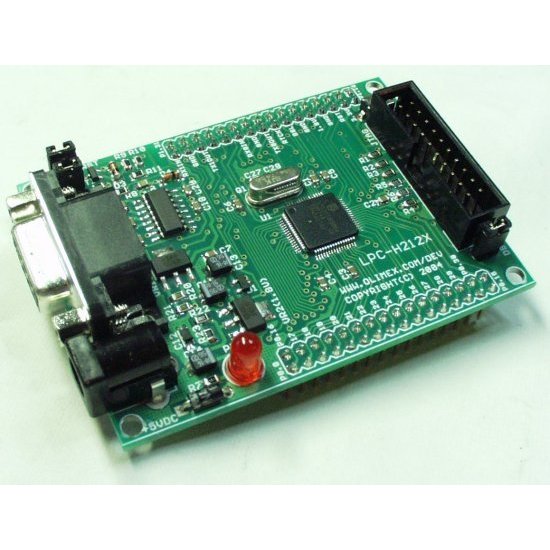
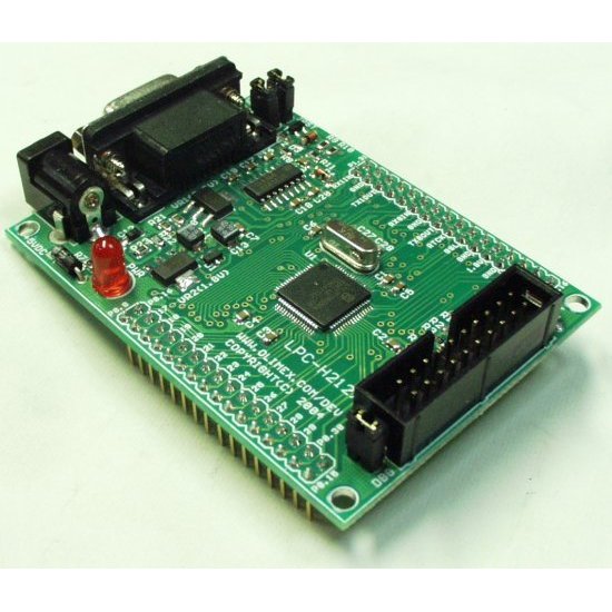
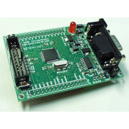
Development board for the LPC2129 processor.
- MCU: LPC2129 16/32 bit ARM7TDMI with 256K Bytes Program Flash, 16K Bytes RAM, RTC,4x 10 bit ADC 2.44 uS, 2x CAN, 2x UARTs, I2C, SPI, 2x 32bit TIMERS, 7x CCR, 6x PWM, WDT, 5V tolerant I/O, up to 60MHz operation
- Standard JTAG connector with ARM 2x10 pin layout for programming/debugging with ARM-JTAG
- Two on board voltage regulators 1.8V and 3.3V with up to 800mA current
- Single power supply: +5VDC required
- Power supply status LED
- Power supply filtering capacitors
- Two channel RS232 interface
- RESET circuit with external control of Philips ISP utility via RS232
- RESET button
- DBG jumper for JTAG enable
- BSL jumper for bootloader enable
- JRST jumper for enable/disable external RESET control by RS232
- 10 MHz crystal
- Extension headers for all uC ports
- FR-4, 1.5 mm (0.062"), green soldermask, white silkscreen component print
- Overall: 3.0x2.2" (76x55 mm)
- Space between the pin rows: 1.9" (48.26 mm)
Comments
Looking for answers to technical questions?
We welcome your comments and suggestions below. However, if you are looking for solutions to technical questions please see our Technical Assistance page.
Customer Reviews
No reviews yet.
False advertising; just bought this board and it's not at all as described on the page or in the schematic. Oscillator is a wacky 14.7456MHz rather than 10MHz for running at max speed. Guess I have to buy a new oscillator if I want to run at max speed. Also, board has a bridge rectifier and requires +6VDC to operate rather than the readily available +5V it advertises. First order from Sparkfun, and maybe the last if I can't count on accurate specs.