- Home
- Product Categories
- PTH ICs
- Optoisolator - 4 Channel

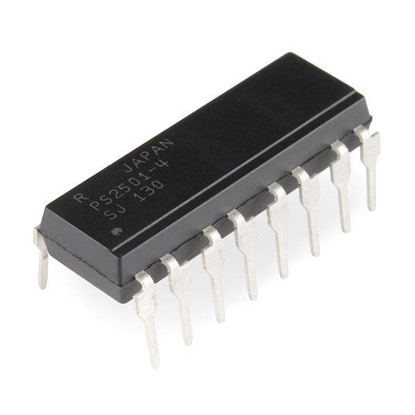
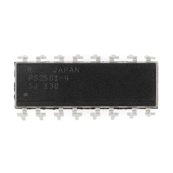
Optoisolator - 4 Channel
Opto-isolator with transistor output for interfacing to noisy loads. This 16-pin dip can be used in conjunction with relays, small motors, etc. to allow a simple microcontroller to turn on and off up to 50mA per channel.
Datasheets:
Optoisolator - 4 Channel Product Help and Resources
Core Skill: Soldering
This skill defines how difficult the soldering is on a particular product. It might be a couple simple solder joints, or require special reflow tools.
Skill Level: Rookie - The number of pins increases, and you will have to determine polarity of components and some of the components might be a bit trickier or close together. You might need solder wick or flux.
See all skill levels
Core Skill: Programming
If a board needs code or communicates somehow, you're going to need to know how to program or interface with it. The programming skill is all about communication and code.
Skill Level: Rookie - You will need a better fundamental understand of what code is, and how it works. You will be using beginner-level software and development tools like Arduino. You will be dealing directly with code, but numerous examples and libraries are available. Sensors or shields will communicate with serial or TTL.
See all skill levels
Core Skill: Electrical Prototyping
If it requires power, you need to know how much, what all the pins do, and how to hook it up. You may need to reference datasheets, schematics, and know the ins and outs of electronics.
Skill Level: Competent - You will be required to reference a datasheet or schematic to know how to use a component. Your knowledge of a datasheet will only require basic features like power requirements, pinouts, or communications type. Also, you may need a power supply that?s greater than 12V or more than 1A worth of current.
See all skill levels
Comments
Looking for answers to technical questions?
We welcome your comments and suggestions below. However, if you are looking for solutions to technical questions please see our Technical Assistance page.
Customer Reviews
No reviews yet.
You should add this to your eagle lib.
Hello, I'm currently trying to optoisolate an Arducam from my APM 2.5 (over 5V serial). Has someone got an example diagram on how to use this to optoisolate 5V serial from an arduino/APM2.5?
Can I use this to control 50 volt loads for long periods of time? I cannot use a pulsed output. Please help me out here guys.
Thanks in advance, tzq33tdq
I bought a couple of these to put between an arduino and some 12V automotive relays. Unfortunately they only are rated for up to 50mA/ch and the coil current of my relay is 75mA so I bought some of the next step up in the series the PS2502-4's from digikey that can handle 160mA/ch.
I’m worried about the power dissipation that is 120mW/ch on both devices. The relay is going to draw 900mW (75mA * 12V) but to calculate the power dissipation of this device I just need to take Vce(sat) which is .3V on the PS2501-4 and 1V on the PS2402-4 and multiply it by Ic of 75mA right? So with the PS2402-4 I would have 75mA * 1V = 75mW and be well within the 120mW / channel rating right?
Is my reasoning here right? Is Ic just the current through the relay like I assumed? Is there any Vbe that I need to worry about (Not sure what this would be with a photo transistor).
Is it ok to drive the relay directly with the opto-isolator or should I just use it for protection and use it to turn on something like a TIP120 instead?
If you want to opto-isolate with this optoisolator, you will have to invert the output by driving a PNP transistor rated above the relay coil current, or use a similar mosfet device that drives hi-side loads. I would not drive relays directly with these optoisolators. Another option is to use the optoisolator, pull the output up to Vss with a resistor, and use that to input a regular CMOS inverting buffer. Then, connect the ouput of the buffer to the ULN2308 darlinton driver described below.
I had a very similar application. I ended up not opto-isolating, and I used the ULN2308 Darlington driver chip (sold here and on Adafruit). The chip is nice because it is 8 channel and already has input resistors. You just connect an Arduino output to a ULN2308 input channel. The corresponding output is a "sink" which will easily handle a 12V relay. The ULN2308 I have already has back-emf diodes in it, which is a plus. The drawback is that your Arduino ground and your car ground have to be tied together.
How well would this work for reproducing analog signals?
and if not well at all, what is a common analog signal isolator?
I have the very same question .. any one have an answer?
omg Im talking to my self ... that what happens when your user name is a number lol
LOL, if you're not into numbers, you can change it on your profile page.
How are you guys wiring this part up for serial comms? Just like the example schematic?
I've found an example online of someone doing the reverse: connecting the TX to the diode's cathode (VCC + resistor on the anode) and doing sort of the opposite on the transistor side as well (RX pulled up to VCC via resistor to collector and GND on emitter). As I understand it, this basically inverts the high/low states based on the input levels, but that didn't quite work for me.
Any tips are welcome.
Thanks!
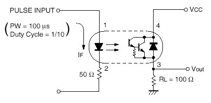
What resistor is recommended to use with this? In the example schematic there is a 50ohm resistor but is that enough when I use the V5 and digital out from the arduino?
Will this work with a 3.3V uC (MSP430) output? What are the voltage min/max voltage levels on the inputs? What about current requirements? Any help is appreciated.
I tested this out with an 3.3V Arduino Pro Mini, and was able to transmit at up to 57600 baud without problems. As bbotany expected, 115200 didn't work.
This works way better than the opto-isolator breakout for transmitting serially. That only worked up to 14400.
i havent tried this at speeds over 9600 baud to back up bbotany's claims of 100kHz, but i got it to successfully send data over rs485 (with sparkfun's BOB --> http://www.sparkfun.com/products/10124) from a netduino+ to a RS485-USB converter on my laptop and into hyperterminal.
For anyone else considering this for isolated interfacing to serial comms of not yet determined levels, it appears that this can handle up to about 100kHz switching, so it can't really be counted on for 115200 serial communication, but probably OK at 57600 and lower.
While the datasheet is correct, the example schemo for this product is not - it shows the darlington output of the single-channel SFE part #COM-00314.
The business end of this device is a single PNP phototransistor. It also does not have the reverse bypass diode of the single channel device.
ss