- Home
- Product Categories
- GPS
- Copernicus DIP Module

Copernicus DIP Module
Replacement:GPS-10923. The new version of this board is built with the Copernicus II, the new drop-in replacement for the Copernicus module. This page is for reference only.
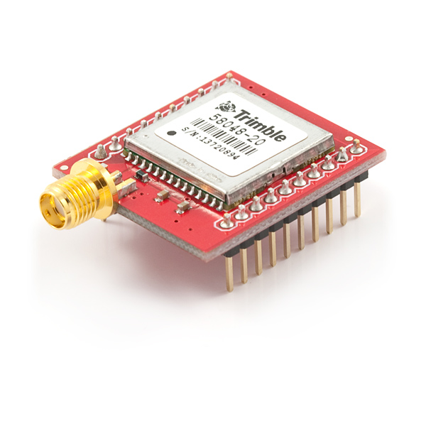
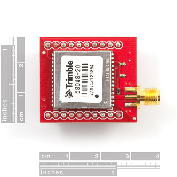
The Copernicus is a great new GPS module from Trimble, but the SMD module prohibits immediate gratification. This DIP allows the customer to gain direct access to the pins on the SMD module. The Copernicus DIP breakout has an impedance-matched, end-launch, standard SMA connector that will mate with our SMA GPS antennas listed below.
Check out our GPS buying guide!
Software:
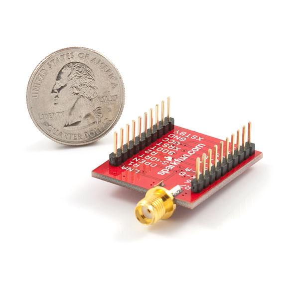
- 1.1 x 1.25"
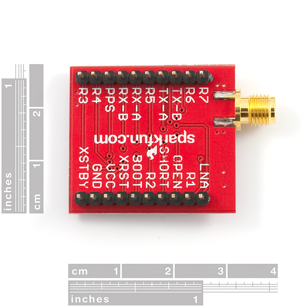
- 0.9" between pins (bread board friendly)
- Copernicus DIP Schematic
- Copernicus Eagle files
- SparkFun GPS Tutorial
- GPS Tutorial by Michael Simpson
Copernicus DIP Module Product Help and Resources
Copernicus II Hookup Guide
December 18, 2013
A guide for how to get started with the Copernicus II GPS module.
Comments
Looking for answers to technical questions?
We welcome your comments and suggestions below. However, if you are looking for solutions to technical questions please see our Technical Assistance page.
Customer Reviews
No reviews yet.
what happened to the module itself? it appears you are not selling it by itself.
How can I get GSV - GPS Satellites in View ? I need to send "GSV" over Serial ? like AT Commands in GPRS ?
Can't configure the unit. Have Copernicus DIP module on GPS Evaluation Board and it navigates fine but no SV information etc shown in GPS Studio. The S/W allows you to configure the unit but, using the GPS Evaluation Board connections USB or RS232 the configuration doesn't happen. Any suggestions?
Do I need to put a Logic Level Converter between the GPS and the Arduino Mega (5v)??
Thx
Andy
Yes, in the manuel, it says it takes 2.7-3.3v.
This unit does not work.
Using this antenna (which shouldn't matter here):
http://www.sparkfun.com/commerce/product_info.php?products_id=177
I hooked up 3.3V to VCC, ground to ground.
I hooked up an oscilloscope to ground, and to both Tx-A and Tx-B (I tried both).
I kept it on outside for 20 minutes . . . it's cold out there! I assume it'll still transmit data if no sat lock is made?
Guess what happens? Nothing. No TLL signal. Tx-A gives a constant 1.8V, and Tx-B gives a constant 0V.
So I start reading the manual in detail, and see this on page 25:
"If you are using the serial port option, the XSTANDBY pin should always be held high."
So I apply 3.3V to this pin, but no change.
page 13 says:
"XRESET Active low logic level reset. Connect to VCC with or without a pullup resistor, if not used."
I apply 3.3V, no change.
Anyone manage to get this to work?
I found that you must hold VCC, XRST, BOOT, R2 and XSTANDY High. This was in the manual, but you have to look at the individual pin descriptions. For standby a pull-up is recommended.
If you are having technical issues with this, you might want to email techsupport@sparkfun.com.
I sent an email on the 19th of November to techsupport, but never received a reply.
When are you going to re-stock this item? We're itching to launch it to stratosphere :-)
Hello,
I was wondering if there is an EAGLE library for this breakout board in the SparkFun library. I could not find it.
If there isn't one, could you please provide the distance between the two lines of pins?
Thanks!
Hi Vovin - the distance between pins is 0.9" (bread board friendly). It's up there in the product description under the dimensional info. I'll add the eagle files as well.
I couldn't find any reference for the pin spacing or connector spacing, so FYI (judging by the eval board dimensional drawing), the pins are on 100 mil centres, with 900mil spacing. I hope that's right...
-PCPete
How did we miss that?! Yep, 0.9" between pins. I'll add dimensions as well. Thanks!
Thanks for fixing the links !!!
The Trimble Studio is worth to try.
Regards
Jorge
The links to the Copernicus Monitor and Trimble Support Tools are broken.
This is the related link I found on the Trimble website:
http://www.trimble.com/embeddedsystems/copernicus.aspx?dtID=overview
Regards