- Home
- Pushbutton Power Switch LV

Pushbutton Power Switch LV
The Pololu Pushbutton Power Switch from Pololu is a compact, solid-state power switch controlled by a momentary pushbutton switch. Because the switched current does not flow through the mechanical switch, a large variety of small, low-power switches can be used to control a substantial amount of power. The use of momentary pushbutton switches also allows multiple switches to be used in parallel to control the power to one load. The solid-state switch also allows the load to turn off its own power, which can be beneficial when used with battery chemistries sensitive to over-discharging. Please note that this switch has several drawbacks when compared to mechanical switches, so please be sure you fully understand this product before using it in your system.
This is the low voltage version operating from 2.5V to 7VDC.
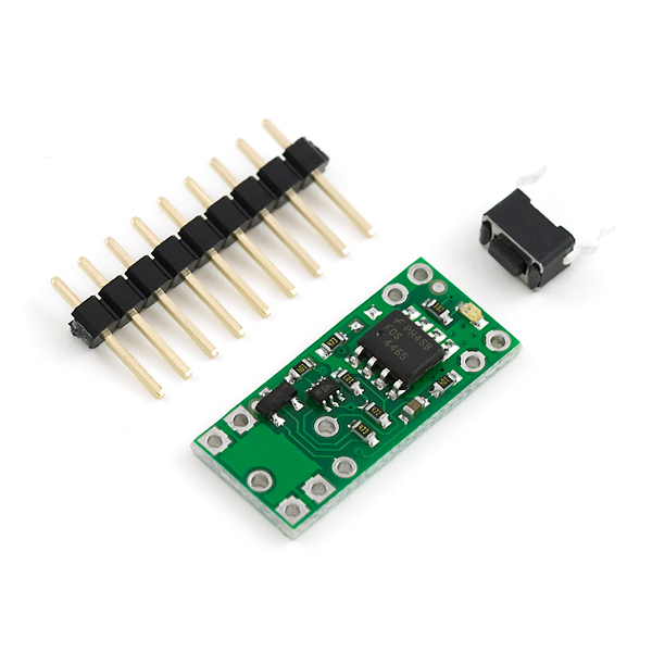
The Power Switch can fit in an 18-pin DIP (dual in-line package) footprint, making it compatible with solderless breadboards and perforated printed circuit boards with standard 0.1" spacing. For such applications, the included male header pins can be soldered to the switch PCB as shown in the picture to the right. Alternatively, wires can be soldered directly to the switch PCB for non-breadboard applications. For high-current applications, make sure that the wires can safely carry the current. Two pads/pins are provided for each of the power nodes, and multiple pads should be used for applications drawing over 5 A.
The included pushbutton switch can be used to trigger the switch. Alternatively, a separate pushbutton, such as a remote panel-mounted unit, can be used instead. Multiple pushbuttons can be wired in parallel for multiple control points, and each of the parallel pushbuttons will be able to turn the switch on or off. The latching circuit performs some button debouncing, but pushbuttons with excessive bouncing (several ms) might not function well with this product. Comes with pushbutton and 9-pin header not installed.
- 2.5-7VDC operating voltage
- 10A maximum current
- Draws very little current in off state, typically under 0.01uA
- Breadboard and perfboard compatible
- 0.4x0.9x0.125"
Pushbutton Power Switch LV Product Help and Resources
Core Skill: Soldering
This skill defines how difficult the soldering is on a particular product. It might be a couple simple solder joints, or require special reflow tools.
Skill Level: Noob - Some basic soldering is required, but it is limited to a just a few pins, basic through-hole soldering, and couple (if any) polarized components. A basic soldering iron is all you should need.
See all skill levels
Core Skill: Robotics
This skill concerns mechanical and robotics knowledge. You may need to know how mechanical parts interact, how motors work, or how to use motor drivers and controllers.
Skill Level: Noob - You will be required to put together a robotics kit. Necessary parts are included and steps will be easy to follow. You also might encounter basic robotics components like bearings, mounts, or other hardware and need a general idea of how it goes together.
See all skill levels
Core Skill: Programming
If a board needs code or communicates somehow, you're going to need to know how to program or interface with it. The programming skill is all about communication and code.
Skill Level: Rookie - You will need a better fundamental understand of what code is, and how it works. You will be using beginner-level software and development tools like Arduino. You will be dealing directly with code, but numerous examples and libraries are available. Sensors or shields will communicate with serial or TTL.
See all skill levels
Core Skill: Electrical Prototyping
If it requires power, you need to know how much, what all the pins do, and how to hook it up. You may need to reference datasheets, schematics, and know the ins and outs of electronics.
Skill Level: Rookie - You may be required to know a bit more about the component, such as orientation, or how to hook it up, in addition to power requirements. You will need to understand polarized components.
See all skill levels
Comments
Looking for answers to technical questions?
We welcome your comments and suggestions below. However, if you are looking for solutions to technical questions please see our Technical Assistance page.
Customer Reviews
5 out of 5
Based on 1 ratings:
Just what we needed... and fast!
Near perfect solution for our prototype and was delivered quickly with no issues. Also very handy to have decent drawings available so we could adjust our CAD model in prep for the parts. When they arrived they fit perfectly. Thanks sparkfun!
A fun project made possible in part by this pushbutton power switch:
http://arduiniana.org/projects/the-reverse-geo-cache-puzzle/
That is an awesome story!
What an epic treasure hunt of a gift, that's extraordinary! I may well do something similar for my mum and step dad's next milestone wedding anniversary, maybe putting in tickets to a nice hotel in Italy or France, making the hotel in question the destination to reach.
I like that tiny little push button they use. Anyone know where you can get just the button?
http://www.pololu.com/catalog/product/1400
For everyone who wants more information about this product, I found the designer's website here: http://www.pololu.com/catalog/product/751
This board has a line to turn de device off when is tied to hi level. What if you need a control line to turn it on too. Is it posible achive this?.
You could add a transistor in parallel across (or instead of) the pins for the button and drive that high to connect the pins.
Unless I missed it above. For reference. I have this hooked up inline to an Arduino Fio. It works great. I have also tested the charging circuit on the Fio. Regardless if this switch is on or not when the power is put to it to charge, it will charge and the red LED will light up.
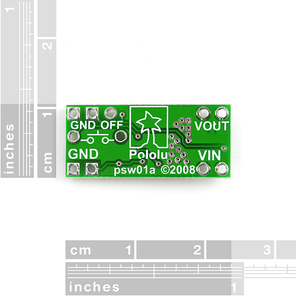
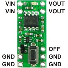
Can someone tell me how to make this work. I see 4 Grounds, two Vin, two Vouts and a OFF pin.
This is how i think it is plug in. Can someone correct me if i am wrong.
So all grounds get connected to the Negative of the battery and microcontroller.
Vin is the Positive of the battery.
Vout goes to positive of the microcontroller.
The Off pin goes to a GPIO and i set it to 5V to turn off the power to the microcontroller