- Home
- Product Categories
- Robotics
- Motor Driver 2.5A MC33887

Motor Driver 2.5A MC33887
Replacement:ROB-11080. The MC33887 has been replaced by the MC33926. It was an epic battle, but in the end, the MC33926 prevailed. This page is for reference only.
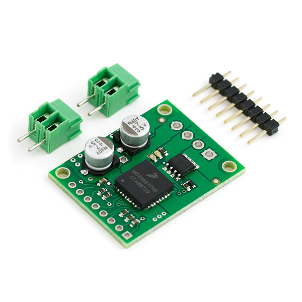
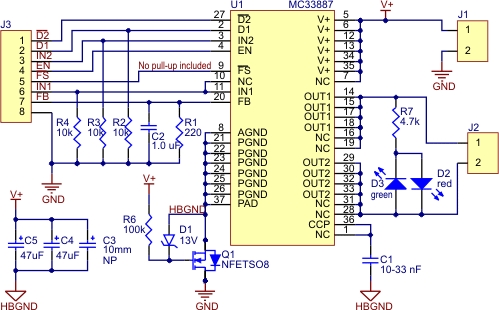
These compact motor drivers based on the Freescale Semiconductor MC33887 motor driver integrated circuit from Pololu are an easy way to connect a motor running from 5 to 28 V and drawing up to 5 A (peak) to your project. The board incorporates all of the components of the typical application diagram on page 25 of the MC33887 datasheet, plus motor-direction LEDs and a FET for reverse battery protection. All you need to add is a microcontroller or other control circuit to turn the H-Bridge on and off.
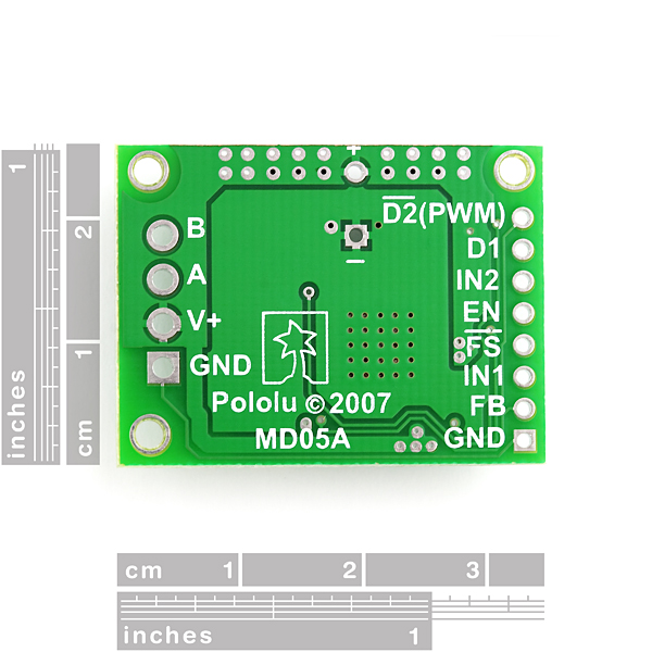
The enable (EN) pin does not have a pull-up resistor, so you must pull it to +5 V in order to wake the chip from sleep mode. The fault-status (FS, active low) output pin may be left disconnected if you do not want to monitor the fault conditions of the motor driver; if you do connect it you must use an external pull-up resistor to pull the line high. IN1 and IN2 control the direction of the motor, and D2 can be PWMed to control the motor?s speed. D2 is the ?not disabled? line: it disables the motor driver when it is driven low (another way to think of it is it enables the motor driver when driven high). Whenever D1 or D2 disable the motor driver, the FS pin will be driven low. The feedback (FB) pin outputs a voltage proportional to the H-Bridge high-side current, providing approximately 0.59 volts per amp of output current.
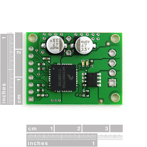
The MC33887 motor driver carrier PCB comes with two 47 uF, 35 V surface-mounted capacitors and holes for installing an additional through-hole capacitor. This third capacitor can be added in conjunction with the two surface-mount capacitors to further limit disturbances on the main power line, or it can be added in place of the two surface-mount capacitors to allow the MC33887 motor driver carrier to function at high voltages.
The MC33887PNB motor driver used on the carrier board has a maximum current rating of 5 A continuous. However, the chip by itself will overheat at lower currents. The actual current you can deliver will depend on how well you can keep the motor driver cool. The carrier?s printed circuit board is designed to draw heat out of the motor driver chip, but performance can be improved by adding a heat sink. (note: the entire PCB can get very hot long before the chip overheats, so be careful not to burn yourself).
Unlike other H-Bridges, the 33887 has a feature that allows it to gracefully reduce current as the current exceeds 5 A or as the chip temperature approaches its limit. This means that if you push the chip close to its limit, you will see less power to the motor, but it might allow you to avoid a complete shutdown.
- 1 motor channel
- 5 to 28VDC operating voltage
- 2.5A continuous output current
- 5A peak output current
- 0.59 V per A current sense
- 10kHz PWM frequency
- Reverse voltage protection
- 1.03" x 1.35"
Comments
Looking for answers to technical questions?
We welcome your comments and suggestions below. However, if you are looking for solutions to technical questions please see our Technical Assistance page.
Customer Reviews
No reviews yet.
Hi, do you guys have a eagle footprint for the MC33887?
Thanks.