- Home
- Product Categories
- Wireless and IoT
- Nordic Serial Interface Board


Nordic Serial Interface Board
Replacement:WRL-10257. The new rev of this interface board fixes a few silkscreen errors that were present. Go check it out.This page is for reference only.
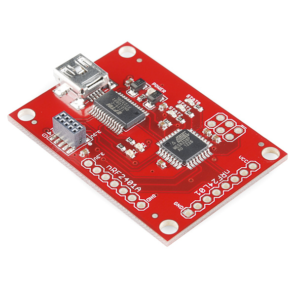
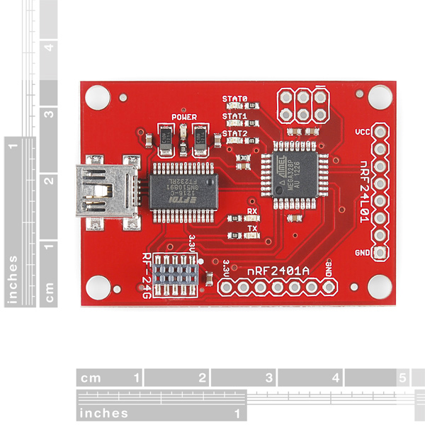
This is a simple serial to USB board that works with the nRF24L01, nRF2401A, and RF-24G Nordic transceivers. Comes with an ATMega168V preloaded with code that allows the transceivers to act as pass through serial devices (sends 4 characters at a time). When powered up, the board will determine which Nordic device has been attached (STAT0 will blink for an nRF24L01, or it will default to an nRF2401A and STAT1 will blink) and run the appropriate code. The LEDs then blink sequentially upon receiving packets over the RF link.
You will need to use VCP FTDI drivers, so that your USB connection comes up as a COM port. Then all you need to do is use a terminal program to communicate with the Nordic transceivers.
**Note: **The labels for the TX and RX LEDs are reversed.
Nordic Serial Interface Board Product Help and Resources
Core Skill: Soldering
This skill defines how difficult the soldering is on a particular product. It might be a couple simple solder joints, or require special reflow tools.
Skill Level: Noob - Some basic soldering is required, but it is limited to a just a few pins, basic through-hole soldering, and couple (if any) polarized components. A basic soldering iron is all you should need.
See all skill levels
Core Skill: Programming
If a board needs code or communicates somehow, you're going to need to know how to program or interface with it. The programming skill is all about communication and code.
Skill Level: Rookie - You will need a better fundamental understand of what code is, and how it works. You will be using beginner-level software and development tools like Arduino. You will be dealing directly with code, but numerous examples and libraries are available. Sensors or shields will communicate with serial or TTL.
See all skill levels
Core Skill: Electrical Prototyping
If it requires power, you need to know how much, what all the pins do, and how to hook it up. You may need to reference datasheets, schematics, and know the ins and outs of electronics.
Skill Level: Rookie - You may be required to know a bit more about the component, such as orientation, or how to hook it up, in addition to power requirements. You will need to understand polarized components.
See all skill levels
Comments
Looking for answers to technical questions?
We welcome your comments and suggestions below. However, if you are looking for solutions to technical questions please see our Technical Assistance page.
Customer Reviews
No reviews yet.
Using the included code and datasheet for the 24L01, it was pretty easy to write code for this. Works great!
*
I actually screwed up my fuses (set it to external osc), and had to carefully wire up and external osc to make it talk to avrdude again!
How did you program it by ISP?
From the schematic the ISP pin out has 3.3 V on the Vcc but my AVR ISP programmer outputs 5.0 Vcc.
I'm new with the AVR chips.
Should I exclude the 5.0 Vcc from the programmer and use the on board 3.3 V regulated from the USB?
What compiler should I do it?...
I just got this, and I'm confused. My Arduino is using a nRF24L01+. My Serial Board is using the nRF2401AG. Seems I don't know how to get them to talk..
I attached the nRF24L01 (Transceiver nRF24L01 Olimex Straight) to the board and I'm trying to make a wireless connection to an other nRF24L01 attached to a PIC18F4220.
Is there a need to program the ATMEga with the C code downloadable from this site, or is the PIC ready to play and if yes, on witch channel does the nRF24L01 receives/transmits data? Thanks Martin
Hey buddies, just want to know if this board is compatible with nRF24L01+. Kindly if there is anyone who has pulled it off, i sure need directions soonest possible.
Thanx.
Is it possible to transmit data from a uC to PC if on the controller I use nRF2401A and on the PC I use WRL-09019 with nRF24L01 on it ? Thanks.
Watch out if you're reading the source code, and using it to write microcontroller code to interface with another nRF20L01+ to establish a link -- the file nRF24L01_lib.c appears to be using 16-bit CRC (lines 109 and 213), but actually switches to 8-bit CRC when it powers up the device (lines 129 & 221). You basically just want to send all the bytes that the code does, and ignore the comments!!
The schematic and Makefile show atmega168, but I see and atmega328P on the card.
I assume I should change the Makefile to atmega328p?
Also, in nRF_USB2Serial.c, line 75 (in the USART ISR), the input byte counter is set to zero when 416 bytes are received. But in the main event loop, a 512 byte buffer is assumed. So, I think 96 bytes of garbage (or maybe all zeros) are sent after every 416 good bytes of data?
That seems to align with what I see when I send large blocks of data. I see what I expect for 416 bytes, a pause where nothing happens, then the results I expect to see for the remaining bytes.
So, I was going to reprogram to see if that fixes the problem. But, 416 is a number that seems like it might have been picked for a reason? Maybe a 512 SRAM part needed those extra bytes for the stack? And someone forgot to change the 512 to 416 in main() also?
Thanks,
Dave Thomas
With a few minor modifications this board can be made much more capable. First, I removed the resistor and capacitor on the AVR's reset line and added a 6-pin programming header, so I could use debugWire for development. Second, the FT232R has a built-in 48 MHz oscillator which can be output straight or divided by two, four, or eight to one of its CBUS (I/O) pins. By adding one jumper wire from an unused CBUS pin to the clock input pin of the ATmega328p, I can run the AVR at 12 MHz instead of the default 1 MHz. Third, I rewrote the firmware to actually use the AVR's SPI port instead of bit-banging it, and I have it talking to an nRF24L01+ at 6 MHz. The AVR's USART is running at 1.5 Mbps compared to the default 9600 bps, for maximum USB throughput. I also enabled dynamic payload size (a feature of the L01+), so it can receive packets with payloads from one to 32 bytes long. Now it's pretty sweet!
Your mods sound very similar to what I'd planned on doing. Naturally, I'd like to pick your brains on that. Any code or documentation you'd care to post would be helpful.
Wow! Nice work. You really pimped your, well, er, Nordic?
If you have pictures or documentation, post it up!
I downloaded from the link "C code (zip)". I see only one file
nRF_USB2Serial.c
It references functions:
tx_data_nRF24L01();
rx_data_nRF24L01();
That are not in this file. Probably the includes:
include
include
Where can I get nRF24L01_lib.c?
Thanks,
Dave Thomas
Just for everyone's knowledge, there's two links for the code. There's the C Code, and the zip for all the files. Click either 'C code' or 'zip' for either. Both links are up there. Thanks!
I wrote some code to read that register but I cannot test it at the moment because I don't have an AVR programmer but it must be something like:
http://codepad.org/vIgGSLTI
Also before calling this the manual says to enable the RX mode and then wait Tstby2a+Tdelay_AGC=130us+40us.
If somebody can test and program this code it will be great!
I'm playing with 2 Nordic Key Fobs + the the interface board then nRF24L01 on ubuntu.
It works great.
It will be good to send also the RPD (received power detector on register 09 bit 0) to the serial so that the programmer can also do proximity sensing.
My apologies!
the source files are there. Something got screwed in either downloading, or unzipping the files.
thanks
Guys,
I am testing the Board with RF-24G daughter board plugged in, by periodically sending 4 bytes of data in 1Gbit/s shock burst mode.
Is that important to set receiver address correctly? If so, what Rx address is preprogrammed into the board?
Would it be possible to get the source code?
The code I downloaded (nRF_USB2Serial.c) explains how to handle USB/Serial functionality, not 24G configuration.
Thanks!
If there is a rev 2 on this board, would be super sweet if there were at least pads for a crystal. Nice to not be limited to 9600 baud using microcontroller RC osc. Then the Mega168 could talk say 115,200 baud to host through FTDI chip -- very handy when you really start using power of NRF24L01.
Works out of the box with an NRF24L01+ reading the keyfob.
However, RX only works with transmitter using a payload size of 4.
I guess changing this values requires modifying the firmware.
Some kind of command over the serial link to change this value would be great.
Be careful! Pin 1 (square pcb pad) on the WRL-00705 and on this board may be opposite! Make sure to check Vcc and GND, as they are clearly labeled on both boards. The pcb in the pic on this page doesn't have a square pad, but mine did.
Other than that, works great. And it captures data from the Nordic FOB right out of the box!
Hi! Does anyone have any tips on a bootloader to change the code on this board? Thanks!