- Home
- Button Pad Controller SPI

Button Pad Controller SPI
Replacement: None. It's time for this product to step aside and make room in the catalog for even more cool stuff. This page is for reference only.
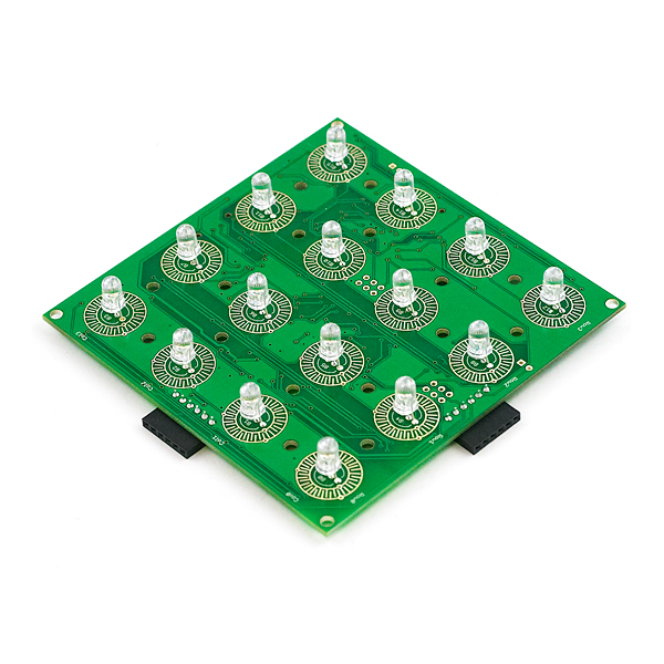
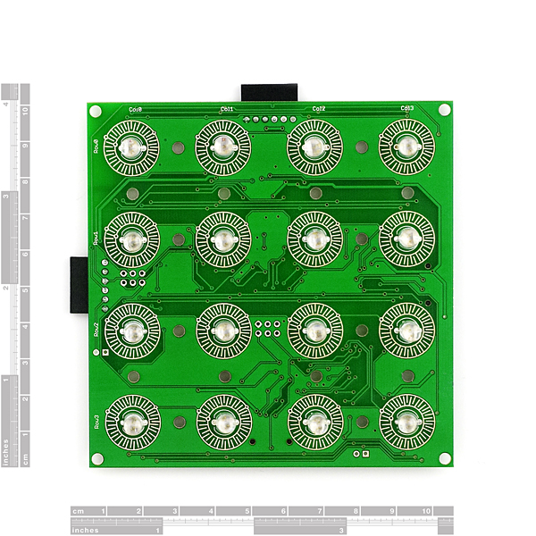
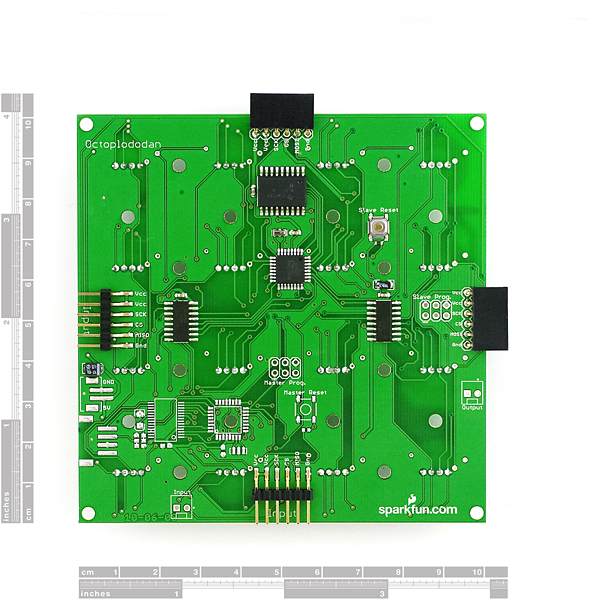
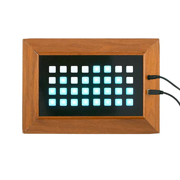
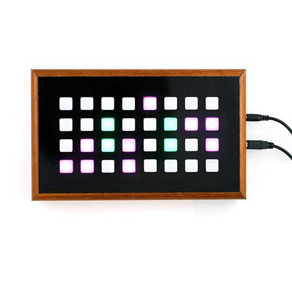
The Button Pad Controller SPI was designed to compliment the Button Pad Controller USB; though it can also be used as a standalone device. The board is 4”x4” and has 16 tri-color LEDs and 16 corresponding button pads (i.e. The button pad surrounds the LED). The boards communicate via an SPI bus, and up to 10 Button Pad Controllers can be connected in a system (including one Button Pad Controller USB). The default firmware uses a 9 bit color scheme. Each board comes configured to work as a standalone unit and must be reconfigured for multiple board systems.
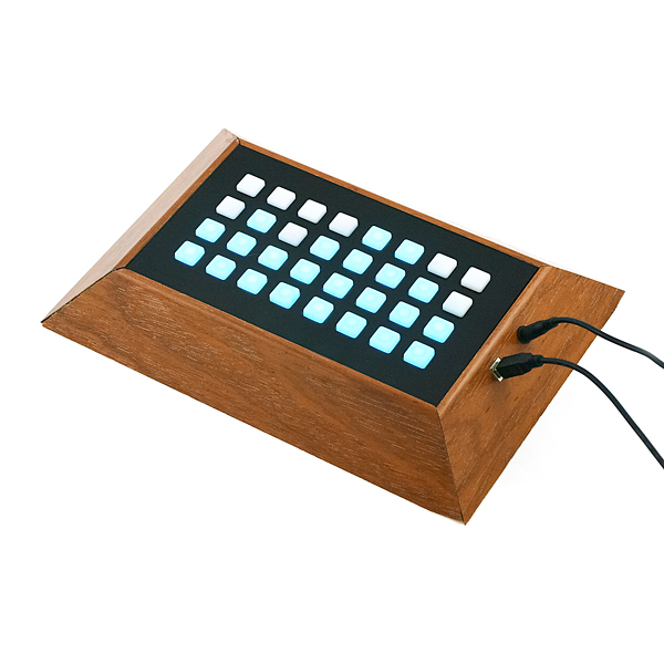
We do not sell the frames shown in the photograph. We put those together for our own use as a demonstration of what two units look like, boxed up together.
Unit comes fully assembled and tested as shown. Unit does not include top button pad (listed below).
Note: We're using new RGB LEDs which have the blue and green pins swapped. When setting the LED color, you'll need to swap the blue and green values in the command structure. Visually, nothing on the board has changed.
Note: Although the hardware is technically capable of 24-bit color, the firmware limits the board to 9-bit color. Check the comments below for the reasoning.
Comments
Looking for answers to technical questions?
We welcome your comments and suggestions below. However, if you are looking for solutions to technical questions please see our Technical Assistance page.
Customer Reviews
No reviews yet.
Word of advice - to get this to work with an Arduino, you will likely have to hand-code an SPI protocol. Luckily, the timing diagram on the User Guide above is very helpful! Here's a video of the board in action.
http://www.youtube.com/watch?v=SguUqEBonNg
Could someone kindly post some code that'll get the SPI on ATMega 328 (on the Arduino Duemilanove) down to 50kHz or lower? As it stands, the ATMega's SPI's slowest speed is 250kHz (five times the max speed of the button pad controller), so if you're planning on getting one of these suckers for use with an Arduino master, I'd suggest you find a fix before dropping 40 American dollars on it...
The slowest the 16 MHz Arduino hardware SPI can go is 125KHz (16MHz / 128). You could figure out how to clock it differently or use an 8MHz Arduino, with the SPI clock / 128 = 62.5 KHz, maybe this is close enough. To set the divider to 128, set bits 0 and 1 of the SPCR register (SPR1 and SPR0) to 1.
I wish these things could do faster SPI. I'm hopeful that since ryowens84 has updated the LED matrix backpack for faster SPI, that this hardware (and software!) will get some love soon.
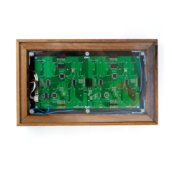
If you look at the pictures, there are no diodes shown. Assuming they send what you see, these boards do not have ghosting protection.
This board, and the USB one, DOES NOT support multiple presses on the same column. Sparkfun Tech Support is not completely sure, but seems to be an hardware problem.
Just an FYI to anyone using their firmware - it is not 24 bit color. All you get from this firmware is the equivalent of 9 bit color. COLOR_DEPTH is defined as 7 which allows only 8 possible color values per color (0-7, anything greater than or equal to 7 behaves the same way). Since 8 is 2^3, the total bit depth is 9, not 24.
Here is the relevant snippet of code:
if(row == 0) frame_num = (frame_num + 1) & (COLOR_DEPTH);
frame_num can never be greater than COLOR_DEPTH which I already showed is defined as 7.
Therefore, this line inhibits true 8 bit depth per color:
if(greenf[LED] > frame_num) lineByte |= (1 << (column + GREEN_POS));
The values of each individual LED are stored in greenf[] and should be able to vary from 0 to 255 for true 8 bit color. However, frame_num can never be greater than 7 as I showed earlier, so any value of greenf[] greater than frame_num is treated exactly the same - maximum brightness. Values between 0 and 7 are truly different, but setting any element of any of the color arrays to a value greater than 7 will yield the exact same brightness.
The firmware is capable of 24 bit color, but not the way it is currently presented. Either the define needs to be changed or the description needs to say 9 bit color.
If anyone has this board or if sparkfun finds another one please email me at cazanv@gmail.com because I would love to take it off your hands for money.
Need it for a school project.
Thank you for that piece of hardware, we had loads of fun playing around with it! ->Extended Tic Tac Toe Game
I emailed Sparkfun about the firmware bug 3 years ago, which was even before I posted my comments proving it does NOT work as advertised. I came across this again just now and noticed the firmware is still posted with COLOR_DEPTH set to 7. Bad, bad, bad. It would have taken less than a minute to correct this error, which would have likely saved many hours of debug among the people who have purchased it.
finally got it!! :D EDIT: or did I?!?! -_- the next day board went back to one board configuration and i cant get to configure it again... any advice guys? im running out of time and patience..
can somebody please provide an arduino code for setting it up for multi board configuration, im struggling hard but i cant figure it out..
We just released a great firmware that turns this alone into a 10 track drum-sequencer with several neat features.
http://www.youtube.com/watch?v=G3KBr0tJkug
https://github.com/Beat707/Beat707-LE
The datasheet shows ATmega48 but the device I got has the ATmega328. Is there an updated datasheet? Its also missing one page. I wonder if I could flash the Arduino 20Mhz Bootloader on this to create an Arduino based Simone game?
It'd be awesome if these used I2C instead of SPI. Then you could address individual panels, and you wouldn't have to clip headers off if you want to make a 2x2 (or larger) grid. You could still update the whole panel by sending updates to all the individual segments (possibly with an enable pin to allow them to simultaneously refresh their display buffers).
I bought 14 of these as well as 3 usb ones. Usb is a waste if you're gonna use these with the arduino. Spi is the way to go. However, half of the boards reconfigured fine for a multi-board setup. The rest did not. Any one have this problem and have a fix? It is just staying on light 0 after doing the config. I'm using the same exact script from the arduino that I used for the boards that did work.
Anyway, I tested and for what I need its perfect, I apologize for the earlier rant.
I managed to get it working on the Arduino using regular pins, not the SPI interface, which is great, as I'm saving that one for something else. ;-)
Here's the working code.
// Manual control of the Button Pad Controller SPI.
// Based on documentation at
// http://www.sparkfun.com/datasheets/Widgets/ButtonPadControllerSPI_UserGuide_v2.pdf
//
// Original code By Havard Rast Blok, 2010.
// Updated by WilliamK @ Wusik Dot Com - http://arduino.wusik.com - (c) 2011
// I/O Configuration //
#define CS 10
#define MISO 11
#define MOSI 14
#define SCK 13
byte lights[3][16]; // [3] = Red, Blue, Green //
unsigned int buttons = 0;
void setup()
{
pinMode(CS, OUTPUT);
pinMode(MISO, OUTPUT);
pinMode(MOSI, INPUT);
pinMode(SCK, OUTPUT);
digitalWrite(CS, LOW);
delay(1);
memset(lights,0,sizeof(lights));
}
void loop()
{
digitalWrite(SCK, HIGH);
digitalWrite(CS, HIGH);
delayMicroseconds(15);
for(int f = 0; f < 4; f++)
{
for(int i = 0; i < 16; i++)
{
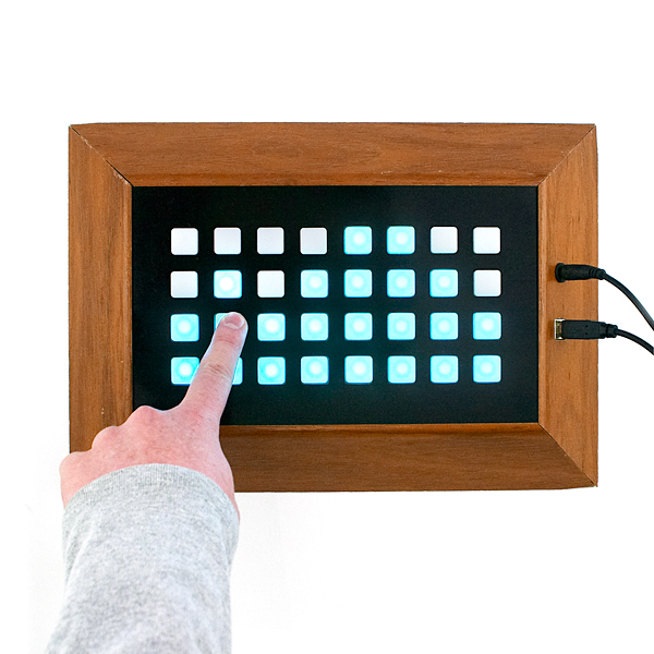
lights[f][i] = bitRead(buttons,i) ? 0 : 10; // lights up when button pressed //
for(int ii = 0; ii < 8; ii++)
{
digitalWrite(SCK, LOW);
delayMicroseconds(5);
if (f < 3) digitalWrite(MISO, bitRead(lights[f][i],ii));
else if (ii == 0) bitWrite(buttons,i,digitalRead(MOSI));
delayMicroseconds(5);
digitalWrite(SCK, HIGH);
delayMicroseconds(10);
}
}
}
digitalWrite(CS, LOW);
delayMicroseconds(400);
}
Edit: never mind, look my post below. ;-)
Maybe check my own project and you will get what I'm looking for: http://arduino.wusik.com
Here's my hand-crafted "SPI" code for the Arduino. There's a link to a downloadable sketch at the bottom of the article. The key to get it right, was the timings and delays, and described in the User Guide from SparkFun.
http://hblok.net/blog/posts/2010/10/17/button_pad_controller_spi
Regarding color depth; yes, I can confirm that it is limited. Either 3 or 4 bits per channel. Somewhat disappointing, as I was hoping to do some color cycling. Are anybody looking at redoing the firmware?
...after a bit more looking and expeimentation, ok, it is indeed 8 intensities as Bandtank says...
...here's what bitrev is, minus loops:
static int
bitrev(int x)
{
unsigned y = 0;
if (x & 0x01) y |= 0x80;
if (x & 0x02) y |= 0x40;
if (x & 0x04) y |= 0x20;
if (x & 0x08) y |= 0x10;
if (x & 0x10) y |= 0x08;
if (x & 0x20) y |= 0x04;
if (x & 0x40) y |= 0x02;
if (x & 0x80) y |= 0x01;
return y;
}
This may well help some of you. Leading spaces are removed on the post by facist software and I can't post long, so more follows...
static void
buttonpad_init(void)
{
// Get shield's SPI driver.
CTL_SPI_DRIVER_t d = nb_shield_spi_driver();
// CS is output.
nb_set_digital_output(BUTTONPAD_CS);
// Configure SSP0.
nb_set_sck(BUTTONPAD_SCK);
nb_set_miso(BUTTONPAD_MISO);
nb_set_mosi(BUTTONPAD_MOSI);
// Configure 8-bit SPI, 50kHz as required by stock firmware.
lm3s_ssi0_init_polled(8, PL022_OPTION_SPI_MODE0);
lm3s_ssi0_set_clock(50000);
for (;;)
{
// Firmware is quite lame.
buttonpad_select_device(BUTTONPAD_CS);
ctl_delay(1);
// Random 4-bit color for each component. Unfortunately,
// Button Pad expects data LSB first, so bit-reverse at this
// level as the SPI driver can't do it!
for (int i = 0; i < 163; ++i)
buttonpad[i] = bitrev(rand() & 15);
// Send LED RGB data and force through status information.
ctl_spi_write(d, buttonpad, 16*3);
ctl_spi_write(d, 0, 16);
// Firmware is quite lame.
ctl_delay(1);
buttonpad_deselect_device(BUTTONPAD_CS);
ctl_delay(1);
}
}
I took a look at the firmware and the schematic. And as far as I can tell, you have four bits for each of the RGB components, i.e. 12 bit color or 4096 colours. That's sort of OK, but contrary to the marketing blurb. I mean, mixing the LEDs isn't exactly great.
Perhaps SparkFun don't really know much about this thing now.
I'm tempted to rewrite the firmware so it's faster, cleaner, and much, much nicer. There's a lot I don't really like about the firmware:
1. CS is active high!
2. When clocking using hardware SPI, the Button Pad expects data in the opposite bit order to standard SPI!
I did get a single board running the stock firmware nicely. You wouldn't know how to get the thing working unless you looked at the firmware.
What I did was bit-reverse all my colour data and constrain it to 4 bits. So, 0-F for the 15 intensities get mapped to 0, 0x80, 0x40, 0xc0, ... You just bit-reverse the byte and shove it out hardware SPI.
Sorry, my code runs on a SolderCore (www.soldercore.com) so it's not much use to you stuck in AVR land.
And I would have thought you'd like n LEDs when configured for n boards, not 'figure out where the LED is'. Count them, not place them!
I've struggled with this four of board using Arduino and the so-called-SPI. I ended to controlling all four with separate SPI-lines (MISO is common).
Wrote some thoughts here: http://mitat.tuu.fi/?p=53
Anyone has a link to a sample Arduino code? is it working with a Duemilanove?
Thanks !
The Schematic only has 2 pages in it while the lower-right corner indicates that there are 3 pages.
Shouldn't the diodes have series resistors to control the amount of current they will draw?
Well, you're correct in that the current needs to be limited to the LEDs somehow. Rather than doing this with LEDs, though, we use pulse width modulation to light the LEDs so that the average current is still low.
What's the limiting factor that prevents you from using more than 10 button pads together?
I have no idea why they say 10 either. This line of code is directly from their firmware:
if(NUMBER_OF_BOARDS == 0 || NUMBER_OF_BOARDS > 16)
NUMBER_OF_BOARDS = 1;
I also gave a quick glance over the algorithm and there is nothing limiting this to just 10 (or 16) except that line. It could be a function of speed as the main loops are somewhat clunky, but the hardware should be able to support it unless they've got something else limiting it that I didn't see.
One other thing - it's not a good programming practice to write variables as all caps. That is universally accepted as the form of a #define.
Hi Rex, Can you post the code you used to get the SPI->Arduino function to work properly?
This looks way cool... I don't see a bunch of diodes on it... does it have the same kind of ghosting protection that the Button Pad 4x4 - Breakout PCB has?