- Home
- Product Categories
- Oscillators
- Programmable Oscillator - 16kHz to 133MHz

Programmable Oscillator - 16kHz to 133MHz
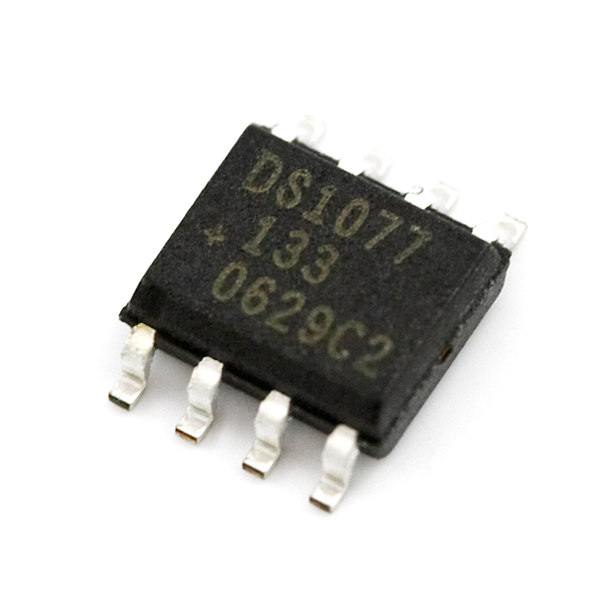
The DS1077 is a dual-output, programmable, oscillator requiring no external components for operation. The DS1077 can be used as a processor-controlled frequency synthesizer or as a standalone oscillator. The two synchronous output operating frequencies are user-adjustable in submultiples of the master frequency through the use of two on-chip programmable prescalers and a divider. The specific output frequencies chosen are stored in non-volatile (EEPROM) memory. The DS1077 defaults to these values upon power-up.
The DS1077 features a 2-wire serial interface that allows in-circuit on-the-fly programming of the programmable prescalers (P0 & P1) and divider (N) with the desired values being stored in NV (EEPROM) memory. Design changes can be accommodated in-circuit on-the-fly by simply programming different values into the device (or reprogramming previously programmed devices). Alternatively, for fixed frequency applications, previously programmed devices can be used and no connection to the serial interface is required.
- Processor-controlled or standalone solidstate oscillator
- Frequency changes on-the-fly
- Dual low-jitter, synchronous fixed frequency outputs
- 2-wire serial interface (I2C)
- Frequency outputs 16.2kHz to 133MHz
- ?0.5% variation over temp (+25?C to +70?C)
- ?0.5% initial tolerance
- Nonvolatile (NV) setting storage
- Single 5V supply
- No external component
- Power-down mod
- Synchronous output gatin
Programmable Oscillator - 16kHz to 133MHz Product Help and Resources
Core Skill: Soldering
This skill defines how difficult the soldering is on a particular product. It might be a couple simple solder joints, or require special reflow tools.
Skill Level: Competent - You will encounter surface mount components and basic SMD soldering techniques are required.
See all skill levels
Core Skill: Programming
If a board needs code or communicates somehow, you're going to need to know how to program or interface with it. The programming skill is all about communication and code.
Skill Level: Competent - The toolchain for programming is a bit more complex and will examples may not be explicitly provided for you. You will be required to have a fundamental knowledge of programming and be required to provide your own code. You may need to modify existing libraries or code to work with your specific hardware. Sensor and hardware interfaces will be SPI or I2C.
See all skill levels
Core Skill: Electrical Prototyping
If it requires power, you need to know how much, what all the pins do, and how to hook it up. You may need to reference datasheets, schematics, and know the ins and outs of electronics.
Skill Level: Competent - You will be required to reference a datasheet or schematic to know how to use a component. Your knowledge of a datasheet will only require basic features like power requirements, pinouts, or communications type. Also, you may need a power supply that?s greater than 12V or more than 1A worth of current.
See all skill levels
Comments
Looking for answers to technical questions?
We welcome your comments and suggestions below. However, if you are looking for solutions to technical questions please see our Technical Assistance page.
Customer Reviews
No reviews yet.
Looks pretty cool, but the frequency range you spec doesn't quite match the data sheet. The DS1077-133 you have pictured ranges from 133 MHz down to 16.2 kHz, not 8.1 kHz. If you need to go down to 8.1 kHz, the data sheet seems to show that you would need the DS1077-66 version.
Thanks - I fixed the description error.
The product name still says "8kHz".
Your Comment is 3 Years old. The title still says "Programmable Oscillator - 8kHz to 133MHz". Just sayin.
still says 8khz, maybe it's time to fix it.
8khz still
You know how slow 8kHz is? Takes forever to change these things...
Just curious if anyone has tried using this at the high frequencies to produce square wave? I also am getting more of a sine wave looking waveform at around 20MHz. I was hoping to get around 30MHz with clean square wave so I'm guessing I'll need to use this clock with some other circuitry. I was thinking high gain opamp and clipping the output with zeners for a 0-3.3V range. Anyone try anything similar (or different in implementation to get clean results)?
Perhaps, a different chip is in need??
does your scope have enough bandwidth to show a proper square wave?
I don't know if I'm being a bit stupid but I can't find the typical rise and fall time on the datasheet. I need a programmable oscillator that has a rise and fall time of between 2 and 5 nano seconds, does anyone know if this will do this?
Cheers
I'm looking for an oscillator to do 16.9344MHz. The closest speed the Frequency Calculator from Maxim gives me is 16.66MHz. Is that close enough? If not, could someone link me one that I could use?
Only you can determine what you can use. Do you want SMT, or through hole? Do you want high accuracy, or do you prefer to save some pennies? How much temperature drift can you withstand?
Start here: http://search.digikey.com/us/en/cat/crystals-and-oscillators/crystals/852333?k=Crystal%2016.9344MHZ
I'm wondering if this can be used as an external oscillator for a uC. My application requires an accurate timebase, won't experience any significant temperature fluctuations, and will undergo MASSIVE accelerations (too great for quarts crystals to survive). I don't have any clue as to how uC's run crystals so I'm not sure how this would work...
A rocket?
Look at the uC datasheet, and you should see a CLK input line near the XTAL pins.
one thing im dieing 2 find is a pwm controller because im having trouble generating a pwm signal @ 25khz off of my arduino to control a 4 pin fan. any1 got any tips?
this chip would not do what you want.
Does it have to be 25Khz? If it can be near it, say 32khz than look here:
http://www.arduino.cc/playground/Code/PwmFrequency
Hi could you confirm that this is the 150mil SO version (DS1077Z), not the 118mil uSOP (DS1077U)?
It's implied by the fact that there is an SOIC converter PCB as a related product, but it would be good to confirm this.
Hmmmm. I'm thinking PicAxe-controlled QRP beacon/transmitter with band-switching. Especially 10M to 6M bands (28MHz/50MHz).
Hmmmm. I'm thinking PicAxe-controlled QRP beacon/transmitter with band-switching. Especially 10M to 6M bands (28MHz/50MHz).
EEPROM wears out in in a finite number of writes(under a few million for a lot of chips).
lol i was just thinking about designing a MCU of this that ran at audio frequencies but used multiple wavetables at independent speeds that could be mixed, all under serial control.
As described in the data sheet, you can control whether or not the EEPROM is written to. So if you're going to use this for frequency hopping, turn that off.
I'm guessing this produces a square wave? Does anyone know if it can produce a sine wave? I know you can get that by filtering the square wave but I'd like to be able to still use the full range.
Also, does anyone know if there is a limit to the number of writes it can handle? What I'm actually wondering is if this could be the basis of a cheap (too good to be true) VFO.
This one produces a square wave. This explains why DDS chips cost way more :p
It's relatively easy to get a sine out of a square wave. Simply add a low-pass filter with the 3db point near the frequency you want out of it. Just make sure that you check the harmonics!
Not sure about the write limits, probably higher than you need to be concerned with though.
The output has gotta be a square wave. Why else would it use a prescaler?
Well, my oscilloscope was showing sine, but there are a few things that could cause it to show a false sine, because of its age.
My scope would show a sine at 20Mhz, since it would only be fast enough to show the primary frequency, not the edges. Show a slow frequency and it'll be square.
Im pretty sure its a sine wave.
Anyone know if you could use this for building an RFID detector/reader for various different frequencies of tags?
A recent Instructable contains lots of helpful material on the I2C Bus along with drivers and example code for the ATtiny2313 and the ATmega168. Has all that's needed to control this chip.
The Instructable is here:
http://www.instructables.com/id/I2C_Bus_for_ATtiny_and_ATmega/