- Home
- Product Categories
- Sensors
- Gyro Breakout Board - IDG1215 Dual 67°/s

Gyro Breakout Board - IDG1215 Dual 67°/s
Replacement: There is no direct replacement for this board, but look around the Gyros category for alternatives. This page is for reference only.
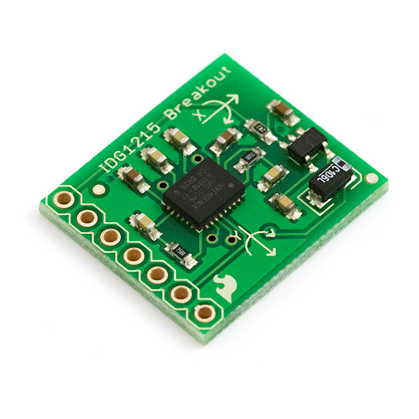
This is the breakout board for the IDG1215, which includes an on-board 2.8V regulator and all pins broken out to 0.1" pin holes.The IDG-1215 is an integrated dual-axis angular rate sensor (gyroscope). It uses InvenSense’s proprietary and patented MEMS technology with vertically driven, vibrating masses to make a functionally complete, low-cost, dual-axis angular rate sensor. All required
electronics are integrated onto a single chip with the sensor.
The IDG-1215 gyro uses two sensor elements with novel vibrating dual-mass bulk silicon configurations that sense the rate of rotation about the X- and Y-axis (in-plane sensing). This results in a unique, integrated dual-axis gyro with guaranteed-by-design vibration rejection and high cross-axis isolation. It is specifically designed for demanding consumer applications requiring low cost, small size and high performance.
The IDG-1215 gyro includes the integrated electronics necessary for application-ready functionality. It incorporates X- and Y-axis low-pass filters and an EEPROM for on-chip factory calibration of the sensor. Factory trimmed scale factors eliminate the need for external active components and end-user calibration. This product is lead-free and Green Compliant.
Not sure which gyro is right for you? Our Accelerometer and Gyro Buying Guide might help!
- 3-7V single-supply operation
- Integrated X- and Y-axis gyros on a single chip
- +/-67 degrees/second full-scale range
- 15mV/degree/second sensitivity
- Integrated amplifiers and low-pass filters
- Auto-Zero function
- On-chip temperature sensor
- High vibration rejection over a wide frequency range
- High cross-axis isolation by proprietary MEMS design
- Hermetically sealed for temp and humidity resistance
- 10,000 g shock tolerant
- Schematic
- IDG1215 Datasheet
- Wiring Example (IDG1215)
Comments
Looking for answers to technical questions?
We welcome your comments and suggestions below. However, if you are looking for solutions to technical questions please see our Technical Assistance page.
Customer Reviews
No reviews yet.
I am having a issue very similar to sergiu. In both an integration and a record player calibration it seems the angular velocity readings are VERY low. (factor of 3 on both axes). I shouldn't even be able to test this unit on a record player! (200 °/sec). Any ideas of whats going on?
When the gyro is not working, maybe check the AZ. This input should be low. When you do not control this input: there is a pull-up resistor to the high side (Vcc) inside the gyro.
Important: the directions that are marked on the break-out board (positive rate for X and Y) are WRONG. I measured negative signals where I expected a positive rate! I checked with the spec sheet from InvenSense and the specsheet confirms my findings. Be aware when you use the gyro for control!
Does anyone know if there is any issue with orienting this board with the x axis vertical? I can't see any but thought I should see if anyone sees an issue.
And as long as we are here, is the equation for x axis degrees/sec = (xout - vref) / 15?
Thanks!
I got an update on the sensitivity issue. All this time I was doing testing on X axis, but now when I decided to thoroughly test the Y axis (why I didn't do it earlier !) it turns out it outputs a constant 1.1V . It would however set to 1.35 with an autozero (AZ) pulse, but will still not react to any movement. So finally I came to the conclusion the particluar device I received was miss- calibrated from the factory. I'll try contacting Sparfun to see if I can get this resolved.
Why were you testing the unit at 132 Deg/sec when its range is +/- 67deg/sec?
It looks like the unit I received has a sensitivity of 5mV/Deg/Sec (instead of 15 mV/Deg/Sec as stated in datasheet) and consequently a range of 1.35/0.005 = 270 deg/sec.
First I noticed that my data readings are 3 times lower than it's supposed to be (15/5= 3). (I was integrating the gyro readings and comparing with accelerometer data).
Then I decided to do a simple experiment, I mounted the gyro on a spinning wheel (drived by a servo) . I measured the rpm using a tachometer (and also by counting cycles). I got 22 rpm and the reading from X output of gyroscope was 0.66V , another test by spinning in oposite direction was ( 27.7rpm and 2.15 V).
Making simple calcualations I got:
22rpm = 22 * 360 Deg / 60 sec = 132 Deg / sec
Delta V = 2.7V/2 - 0.66V = 1.35V - 0.66V = 0.69V
From this sensitivity = 0.69V / 132 Deg /sec = 0.00523 V/Deg/sec
If you do calculations for the other measurment (27.7rmp 1.41 V you'll get similar results 0.8/166.2 = 0.00481 V/Deg/sec).
Now am I missing something or is device out of spec ? Did anyone else got same issue ?