- Home
- Product Categories
- Wheels
- Wheel Encoder

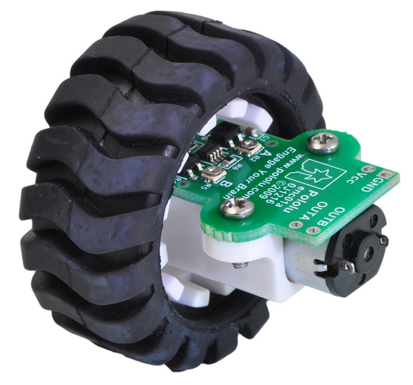
Wheel Encoder
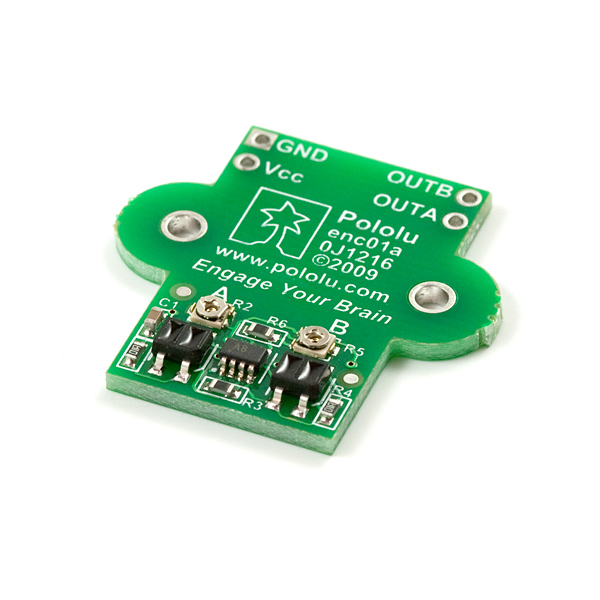
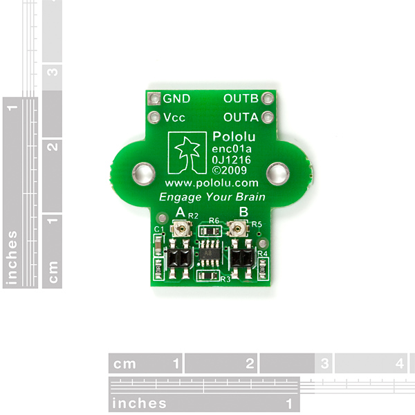
This quadrature encoder board is designed to hold two infrared reflectance sensors inside the hub of the 42x19mm wheel and measure the movement of the twelve teeth along the wheel?s rim. The two sensors are spaced to provide waveforms approximately 90 degrees out of phase, allowing the direction of rotation to be determined and providing four counts per tooth for a resolution of 48 counts per wheel rotation. Each analog sensor signal is fed to a comparator with hysteresis to provide glitch-free digital outputs. The compact layout of the board fits all of the components within the envelope of the hub and tire, allowing the board to be mounted between the motor and a chassis. The encoder is calibrated for operation from 4.5 V to 5.5 V, but it can be recalibrated for operation at 3.3V .
The two outputs of the encoder are digital outputs that can be connected directly to digital input pins on most microcontrollers (inputs that can generate interrupts on change are recommended). With 48 state changes per revolution of the 42 mm wheel, a speed of 1 m/s (a bit over 3 feet per second) generates approximately 360 state changes per second. With two encoders used simultaneously, as is the case for most differential-drive robots, the encoders will require attention almost every millisecond. Decoding the encoder outputs should only take a few percent of the processing power of a microcontroller such as the Atmel ATMega168.
- 4.5-5.5V operating voltage
- 2 digital outputs
- 14mA consumption at 5V
- 48 counts per revolution (linear resolution just under 3mm)
- 2A continuous paralleled output current
- 100kHz maximum PWM frequency
- 2.7-5.5VDC logic voltage
- 1.6g
Wheel Encoder Product Help and Resources
Core Skill: Soldering
This skill defines how difficult the soldering is on a particular product. It might be a couple simple solder joints, or require special reflow tools.
Skill Level: Noob - Some basic soldering is required, but it is limited to a just a few pins, basic through-hole soldering, and couple (if any) polarized components. A basic soldering iron is all you should need.
See all skill levels
Core Skill: Robotics
This skill concerns mechanical and robotics knowledge. You may need to know how mechanical parts interact, how motors work, or how to use motor drivers and controllers.
Skill Level: Experienced - Your experiences should include working with stepper motors and feedback system. You may need to understand how encoders and more complex control systems work.
See all skill levels
Core Skill: Programming
If a board needs code or communicates somehow, you're going to need to know how to program or interface with it. The programming skill is all about communication and code.
Skill Level: Competent - The toolchain for programming is a bit more complex and will examples may not be explicitly provided for you. You will be required to have a fundamental knowledge of programming and be required to provide your own code. You may need to modify existing libraries or code to work with your specific hardware. Sensor and hardware interfaces will be SPI or I2C.
See all skill levels
Core Skill: Electrical Prototyping
If it requires power, you need to know how much, what all the pins do, and how to hook it up. You may need to reference datasheets, schematics, and know the ins and outs of electronics.
Skill Level: Noob - You don't need to reference a datasheet, but you will need to know basic power requirements.
See all skill levels
Comments
Looking for answers to technical questions?
We welcome your comments and suggestions below. However, if you are looking for solutions to technical questions please see our Technical Assistance page.
Customer Reviews
No reviews yet.
2A continuous paralleled output current? What is this talking about?
I think it's accidentally copied over from the 1 amp dual motor driver specs.
does anyone have another suggestion for a general purpose rotary encoder?
learned movements are so interesting!
Can this encoder be used at a higher resolution or is it specifically designed for the wheel? (i.e. If I make my own wheel with 32 16 counts per tooth or something like that?)
It's possible, but I think it would be very difficult to get something working well. To get a working quadrature encoder, you will need to set up the your wheel so the teeth generate signals approximately 90 degrees out of phase. The height and thickness will also probably affect the results. Pololu has a schematic of the board if you want to better understand how it works.
See the instructions at the bottom of this page, under the section titled "Modifying the Encoder for 3.3 V Operation".
Is shorting R4 all that is need to make this encoder work at 3.3v?
It also mentions recalibration. How do I do that?
Thanks