- Home
- Product Categories
- Sensors
- IMU 6DOF Razor - Ultra-Thin IMU

IMU 6DOF Razor - Ultra-Thin IMU
**Replacement: **SEN-10010. The new version of the board removes the high-pass filters which were creating some issues with the output. This page is for reference only.
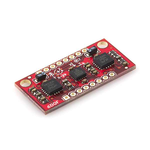
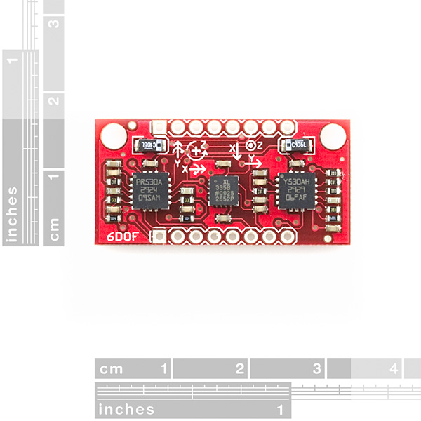
There's a lot of punch packed into this little IMU. The 6DOF Razor makes use of ST's LPR530AL (pitch and roll) and LY530ALH (yaw) gyros, as well as the popular ADXL335 triple-axis accelerometer, to give you six degrees of measurement on a single, flat board.
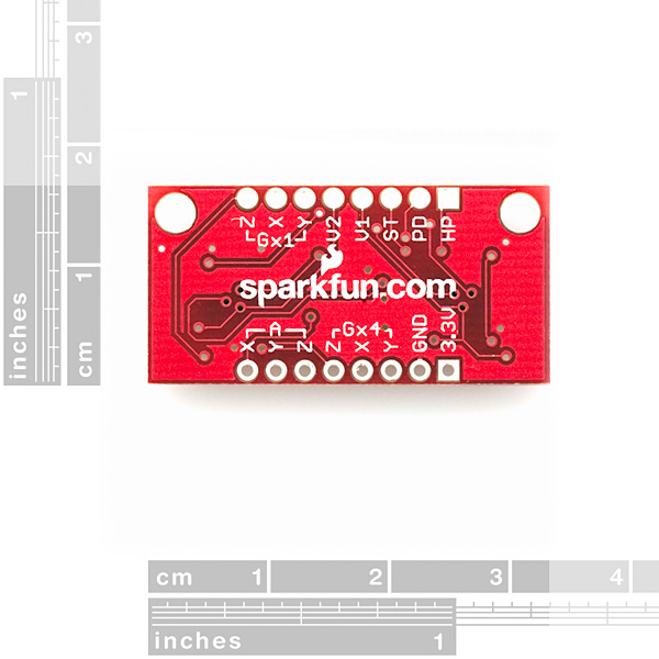
All analog outputs of the gyros (1x and 4x amplified) and accelerometer are broken out to the 0.1" pitch headers. The gyro outputs have a full scale of ±300°/s, while the outputs of the accelerometer have ±3g range.
There is no on-board regulation, so you'll need to provide a clean 3.3VDC power source, which will power all three sensors. All filtering capacitors and other components are included as shown on the pictures.
Having a hard time picking an IMU? Our Accelerometer, Gyro, and IMU Buying Guide might help!
- 2.7-3.6VDC power supply
- Low power consumption
- Pitch, yaw, and roll gyro outputs
- 1x and 4x amplified (0.83 and 3.33 mV/°/s sensitivity, respectively)
- ±300°/s range
- x-, y-, and z-axis accelerometer outputs
- 300mV/g sensitivity
- ±3g range
- All necessary filtering components
- Access to gyro's self-test, power-down, and high-pass filter reset pins
Comments
Looking for answers to technical questions?
We welcome your comments and suggestions below. However, if you are looking for solutions to technical questions please see our Technical Assistance page.
Customer Reviews
No reviews yet.
Hi all,
I wrote some simple code to connect Razor IMU with Arduino - basically to read raw data. Also I ported code for state estimation based on DCM algorithm ( same end goal as Kalman filter). You can find write-up and code at :
http://voidbot.net/razor-6dof.html
Hope this helps someone
Thanks for the code! Found it very useful to get up and running right away.
thanks for the codes.
i didnt test it yet, i am newbie for software based filters and analog sensors.
what will give these codes to me?
what kind of data? angle?
i need x-y-z angle for meausering angles between board and ground.
how can i use that codes for that?
thanks again
you'll need a magnetometer to correct the bias of the gyros on the z-axis. With this board you can get pitch and roll.
oops. I stumbled on this looking for a SPARC Server
It would be helpful if you could provide us with the eagle library. I'm too lazy to make the gyro symbols / footprints by myself ^^
In addition to an eagle library part, a fritzing part would also be useful
Is there a datasheet for the IMU? Like the Atomic IMU 6 Degrees of Freedom - XBee Ready?
Its only really a breakout board, but it would be nice if Sparkfun did put together a datasheet explaining all the pins simply and the maths required for conversions etc so we dont have to go looking through 3 datasheets.
What do you think about this IMU in a Quadrotor???
Using the gyros x4 output, they take a while to return to zero (1.23v) after a move. I've been bench testing and have the following results: See plot here: http://i28.tinypic.com/vfdqfk.png
There are two moves on this plot, first is 90 clockwise , then a pause, then 90 degrees back to the start point.
You can see after the first move there is a decay back to the rest position. Why? How do I get rid of that delay / decay? I'm using the device to measure angular position in 3 axes, (integrating deg/sec data) which is not looking good due to this false movement.
Any help would be great.
The issue is due to the time constant of the RC high pass filter being too high. We should have a revision that removes the filter released within the next three weeks.
Until then, talk to techsupport@sparkfun.com about the issue.
Thanks for the response!
I will contact tech support.
Hi D.Walt,
I also have a 6DOF that I have not powered up yet.
I would like to do the necessary mods before soldering it in place, but before I remove the high-pass filter I would like to know if you did pulse the high pass filter reset pin either on power up or after you measure a saturated output.
Thanks.
ang.mack
I am having the exact same problem with this IMU. The accelerometer outputs are rock solid, but the gyro outputs take quite some time to return to zero after movement stops. In Fact, the gyro output seems to over shoot zero and since I'm integrating the data and accumulateing it in a single variable, the initial move is canceled out.
I would appreciate any guidance anyone has to offer.
Can any one help me, i need to use lipo bateries of 3.7v for this proyect what other component can i use to regulate de voltage to 3.3 in order to use this IMU??.
or can i use directly the bats?
Unfortunately the components on the board all state that they won't run at greater than 3.6V and we don't recommend trying. More than that will likely damage the sensitive (and expensive!) components.
It is always best to try to provide a regulated power supply to a board, especially one with sensors. But your case is difficult as going from 3.7V to 3.3V is hard. Linear regulators need some overhead (called dropout voltage) in order to produce the output voltage; our standard regulator has a dropout voltage of 1V so it takes 4.3V (or greater) to make 3.3V. So that won't work.
Switching converters have similar issues when the input and output voltages are close together (or even cross, for example while a battery is draining). There is a configuration called "boost/buck", where one converter raises your 3.7V to, say, 5V, and a second converter drops that to 3.3V. This works well, but can be inefficient: if each stage is 80% efficient, you'd only get 64% total efficiency.
Your simplest option may be to put a diode in series with your battery. One diode should drop the voltage around 0.7V, but different types of diodes have different characteristics so measure it to be sure it works. Be sure the diode can handle the current you'll be drawing through it (which shouldn't be a problem for the Razor). The output voltage will also fall as the battery voltage drops, so be aware of that when you're troubleshooting problems. Good luck!
the gyros on this board turns me crazy!
i have the problem that every axis on this board react fast if the motion starts but if the motion stops the value needs some time to turn back to zero.
a solution that works a bit is to set the HP filter - each time if i read the values - but than i got not the right angles.
if turn the sensor 90? i get 29? and even this value changes dependents on the delay of that i have inside the loop?
i got today also a idg500 Gyroboard ant this works more the fine!
so could this be a problem of this IMU board ?
here is the code:
gyro_z = getAdc(8);
float newTime = millis();
float savetime = newTime - oldtime;
oldtime = newTime;
// (currentGyroValue * Vdd / AdcRes - ZeroRateLevel) / Sensitivity(3)
gyroRad_z = ((gyro_z * 3300.00 / 4096.00 - 1230.00 ) / 3.33);
currentangle += gyroRad_z_0 + ((gyroRad_z) * ( savetime / 1000.00)) ;
digitalWrite(3,HIGH);
delay(20);
digitalWrite(3,LOW);
hey
i got the same problem, too :(
every time motion stops, the gyro-values need up to 3sec to get back to zero
has anyone an idea, how to get rid of this problem? i can't believe, that the gyros on the board are so bad...
at boa300
I have similar issue with the 6DOF IMU, but signal of Gyro x/y is not stable. After request at customer service, they suggest to check the signal by osci. As I don't have any osci right now and the ACC and yaw gyro are still working/stable, I assume that the 6DOF IMU is damaged somehow. Also the self test does not stabilize the signal to certain value. Maybe it's ESD issue. If anybody else has another idea, please let me know. Its just not so a cheap IC to replace it easily...
Output impedance for the accelerometer is approx. 32k Ohms (from the datasheet). For the non-amplified channels of the gyros, it's 33k Ohms (from the schematic). For the amplified channels it's likely much less and probably insignificant to the input impedance of the Picaxe ADC. If you're worried about the accelerometer, you can buffer the signal with a unity gain op-amp/voltage follower.
Has any one had this problem? I just got my 6DOF Razor today and tried it out; the accelerometers works likes a charm, the Z-axis gyro read well, but the Y ans X axis gyros have readings that don't change. Please help!
can someone tell me what is the output impedance for this imu... i want to use it with the picaxe 20x2? thanks for your help
Anyone here knows the reason for the HP Filters (gyros) that SF put on this BOB?
I just got mine and I'm wondering if I should remove them... any suggestions?
It would be clearer if in the schematic the L1 and L2 connector/jumpers were the other way arround - as they would be looking from the top of the board.
Has anyone used this thing as a replacement for XY & Z sensors on the ArduPilot? Is it plug and play or do I need to be an engineer to get it to work?
This is not a plug & play replace for those sensors. You will need to do some math to adjust this little board to your needs...
Hi!! i still cant get the gyroscopes to work, when i tilt the IMU, i have a constant voltage in all the 3 gyro (the amplified outputs, the normals don't work too).
Do i have to do a sequence at the start for the self test??
Does anyone have the same problem??
Thanks!
Other quick remark:
When you wrote the comment, all 6DOF had the HP filter that would hide the constant part of the output signal, i.e. for instance if you were rotating the 6DOF at a constant speed.
Quick question: when you say "when I tilt the IMU", do you mean that it is sitting still although tilted?
If so your readings are normal - the gyros measure an angular speed - you need to be currently rotating the IMU to see the gyros output change.
I just got one of these (awesome!) but my gyro outputs look funny. The LPR output (after going through a PIC18F452 ADC) is pinned to 384 (ADC count), which is right where it should be for zero output, but instead of zero-mean noise, it's like I'm only getting the bottom half of the noise. There are occasional bumps over 384, but it's either that or lower, with a very flat top. The LY is fine, but the ADXL does it sometimes on a few of the axes. Anyone else run into this problem? It works so great otherwise that it makes me think I did something silly getting it set up!
I just got one, and can't wait to build ... er ... well I'm happy I have one and look forward to using it :D!
is there anything about 6 dof imu with arduino?
myHalici: is there anything about 6 dof imu with arduino?
There is :) . See http://voidbot.net/razor-6dof.html
I just posted it in comments (obviously before seeing your question....). See it under Nov 5th date
Im tyring, but only got this readings:
256|253|315|516|516|516
256|253|315|516|516|516
256|253|315|516|515|516
257|253|316|516|516|516
256|253|316|516|515|516
256|253|315|516|516|516
256|253|315|516|515|516
256|253|316|516|516|516
256|253|315|515|516|516
256|253|315|515|516|516
256|253|315|516|515|516
256|253|315|515|515|516
256|253|315|516|516|516
256|252|315|515|515|516
256|253|316|516|516|516
256|253|315|516|515|516
the accelerometers work, but the gyros are not working, still don't know why...
I've had my eye on both gyros and accelerometers for my next project. I planned it out last winter and waiting until this winter made it simpler and smaller. Way to go, Sparkfun!
Thanks for all the comments.
What processor do you use it with?
I am considering a NXP LPC2148 or 2138 (depending on whether I want to go USB right away or just use a UART).
Has any one of you guys used them?
Thanks and best regards.
Hin hin - well, next time I will pay attention before asking silly questions.
I just found your logomatic.
Too bad thmany pins of it are not driven even just to a via next to the chip!
Still, just give me time to make my mind and fetch my credit card...
For the LYSI, it was around 4,5 kHz.
There are some complaints about this for RC models (read this on DIY drone forum and on a german RC forum).
The LY530AL datasheet give also 4,5 kHz.
No info for the 530.
Regarding noise, I have done some allan variance measurment, AD is first then ST and Invensense last.
I am trying to find allan variance noise characteristics on gyros, but most datasheets don't include it. Have you posted your measurements anywhere online? Also, which sensor models did you compare?
Does anybody have any idea what the resonant frequencies of these new gyros are? It's not in the datasheets, and I'm wondering if it is higher than the LISY300AL.
frank36080115, I'm a bit confused about your comment, too. For triaxial accelerometers, gravity acts in the Z-axis - the MEMs technology should take care of that orthogonally for the other axes. As far as aligning an X-axis accleration with a Y-axis rotation, that doesn't apply to the relative acceleration acting on the rate sensor - that would be nulled out internally. For the user, aligning the axes would make more sense (even if its aligned in opposite directions) for the resolution of motion.
By the way, I am curious why the invensense gyros were not chosen for this board - the IDG-500 and ISZ-500 have better resolution than the ST gyros with the same 4X gain circuitry and the single z-axis sensor is cheaper than throwing away the Y=axis of the LY530 sensor.
imagine if you glued this board onto a stick aligned with the X axis, and then held the stick horizontally while spinning it, then only X and Z axis accelerometer and the gyro axis labeled X would output a signal indicating that it is rotating
i figured that since this thing is perfect for building UAVs. And from the UAVs i've seen people build, people usually integrate the angle from the gyro, and then use the corresponding accelerometer to slowly eliminate the gyro drift. if you wanted to eliminate the drift from the X axis gyro, on this SparkFun board, you would use the acceleration data from the accelerometer labeled X.
so that's why i think it makes sense for SparkFun to label them this way. i think they may have thought of use cases like above, nobody bothers using these IMUs for absolute position sensing since it won't be accurate (double integration of accelerometer data while in rotation? good luck)
Agreed with just a few remarks:
(1) First experimentation tells how axis are aligned and directed - then SMOP.
(2) As for deriving (well, in fact integrating) the absolute position, it all depends on (a) whether the sensors ever saturate, (b) if your application can zero the sensors accurately over a period of time and (c) how long your measurement lasts compared to the imprecision of the sensors.
Mine lasts for a few seconds - I am more concerned about accelerometer saturation at this point.
First, I assume you meant:
[...] aligned with the X axis gyro [...]
This is also my first point about this: You shouldn't have to qualify the direction you're talking about with which set of axes you're using.
[...] to eliminate the drift from the X axis gyro [...] data from the accelerometer labeled X. [...]
You need readings from both the X and Z (your sine and cosine) to get an absolute angle measurement. Otherwise you don't know which side you're on. (Remember that trigonometry?)
So, lining them up would be easier since you remember to correct a gyro axis with the other two axes.
And I was trying to make this comment constructive, not demeaning.
And I ran out of words for full arguments and special cases...
I'd be curious to know whether others' experience has been the same as mine, but it seems to me that InvenSense parts are much harder to source than the ST components. Also, while it's perhaps not directly related to this, I have yet to get a response from InvenSense to multiple emails asking about their IME3000 accelerometer (which includes an interface to their gyros). I eventually went to ST, partly out of frustration over that.
I've had the same problem with info for their accelerometer. I think, so far, it's just a prototype and they're working the 'bugs' out. Meanwhile, try the Analog Device's ADXL345 if you want digital tiaxial accelerometer in a small package for just a small $$. AD has let me try one for free with an eval board (someday they'll ask for it back, I'm sure) & it's a little marvel.
While I'm on the subject of AD, they have complete 6 DOF (one with a compass, too) modules which are 10 x 10 x 10 mm -but also $350-450 in quantity. Still lower than alot of other integrated IMU's, but beyond the tinker's price range.
Why didn't you align the gyro and accelerometer axes in the same direction? You have the x and y axes pointing in different directions ... at least that is what the silk screen says.
The static acceleration on the accelerometer's X axis due to gravity relates to the angular velocity on the same axis, so the way SparkFun labeled them does make perfect sense. This makes it easy to implement filtering that utilizes both instantaneous gravity measurements and the integral of the angular velocity to calculate absolute angle of the board relative to the ground.
The acceleration due to gravity as measured by all three axis is related to the angular acceleration about all three axis. There's nothing easier about having one set of axes be left handed and one set right handed on the same board. It might be slightly more complicated if you aren't deriving the filter from first principals and are using any reference which uses a consistent set of axes.
When did the ST stuff come out? I was only aware of the Evensence flat gyros...
For the benefit of others who might have the same confusion I had in understanding the part numbering for ST's gyros, I thought I'd point out that the 300 degrees per second range is on the 4x amplified output (and corresponds to the more sensitive of the two numbers above). The unamplified output in fact has a range up to 1200 degrees per second, and is less sensitive.