- Home
- Product Categories
- Kits
- Capacitance Meter DIY Kit

Capacitance Meter DIY Kit
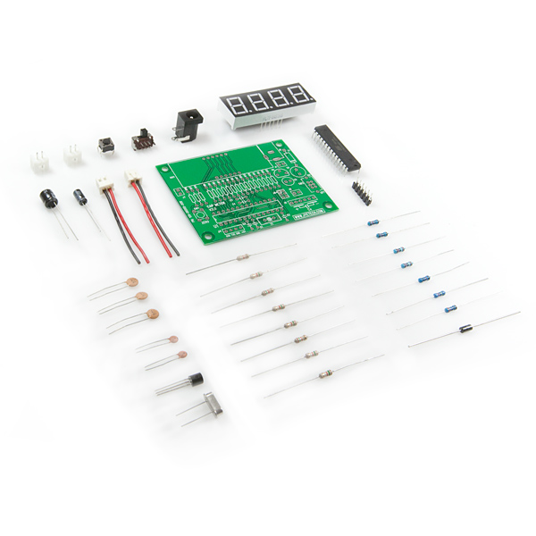
This kit includes everything you need to make your very own capacitance meter, able to measure caps anywhere between the range of 500uF to 1pF. Many multimeters are able to measure capacitance, but they're rarely as precise as a dedicated capacitance meter. Not only does this product provide a great chance to hone your soldering skills, but you also come out with an accurate, fully functional, capacitance measuring tool.
Assembly is very straightforward, and all components are through-hole. You'll get a chance to solder a wide range of components such as resistors, seven segment LEDs, a 28-pin ATmega48 microcontroller, and more!
An 8-16VDC power supply is required, but not included.
- About 1% accuracy, <2% error
- Measuring range: 1pF - 500uF
- Automatic range switch
- Zeroing available
- Real time serial output of measurement read-outs with time stamp
- Low cost and easy to build
- Power supply voltage: 8-16VDC
- Power supply current: <30mA
- User's Manual
- Schematic
-
Be sure to checkout our Surface Mount Soldering Tutorial and our SMD soldering guide.
Capacitance Meter DIY Kit Product Help and Resources
Core Skill: Soldering
This skill defines how difficult the soldering is on a particular product. It might be a couple simple solder joints, or require special reflow tools.
Skill Level: Rookie - The number of pins increases, and you will have to determine polarity of components and some of the components might be a bit trickier or close together. You might need solder wick or flux.
See all skill levels
Core Skill: Electrical Prototyping
If it requires power, you need to know how much, what all the pins do, and how to hook it up. You may need to reference datasheets, schematics, and know the ins and outs of electronics.
Skill Level: Rookie - You may be required to know a bit more about the component, such as orientation, or how to hook it up, in addition to power requirements. You will need to understand polarized components.
See all skill levels
Comments
Looking for answers to technical questions?
We welcome your comments and suggestions below. However, if you are looking for solutions to technical questions please see our Technical Assistance page.
Customer Reviews
4.4 out of 5
Based on 21 ratings:
1 of 1 found this helpful:
Very good cap meter for the price
This is a super cool kit because not only is it good practice to build, but you end up with a useful tool at the end of the day. I've been quite impressed with the accuracy of this meter and believe it might exceed the rated specs. I guess it'd be nice if it included a case, but that'd raise the cost and you may as well just make your own by repurposing an Altoids tin or 3D printing a custom one.
I guess my only gripe is that the firmware doesn't seem to be open-source as far as I can tell, even though it's based on the really common atmega328p. I'd like the ability to add more features to it, but oh well. They have the hex file available to download, but that's only useful if you fry the µC and have to replace it.
1 of 1 found this helpful:
Easy to build and really useful!
It went together in an evening and worked the first time. Now that its done I am looking for a simple case for it. Too bad it is a little wide for the Altoids mints tins. I will look to sparkfun for other products in the future. Thanks for the Great Kit
2 of 2 found this helpful:
I carefully built this kit and found that it does a very good job of measuring caps. I might want bigger holes in the measurement terminals. I did goof the polarity on the filter cap and had to replace it. However, that was my bobo. Measuring and sorting the resistors is a must before putting them into the board. I handled the unwanted electrical contact problem by covering the underside of the board with some stick on fun foam from a craft store. Recommended.
3 of 3 found this helpful:
I am surprised at how useful this is.
I bought this on a whim just to see if it would actually measure capacitance levels as well as and below what my WaveTech multimeter does. Surprisingly, this unit does indeed measure the capacitance values quite well. My WaveTech didn't have the resolution (needs another digit) to show me anything like the 22 pF we use on our boards. This one does it well!
The assembly is easy and straight forward. Some hints: A) Make sure you have the polarity on the electrolytic capacitors correct. You might want to use an ohmmeter and reference the schematic to make sure you know where the +/- side is on the board. B) I would suggest you measure all those resistors as you insert them in the board. The color bands are very small so I immediately got the ohmmeter out just to make sure.
Once you have it assembled you may ask: how do you keep it away from all that "conducting" stuff on your workbench?
I found that it will fit very nicely in an Altoids tin. Cut a durable piece of plastic the shape of the tin and place it under the capacitance checker. Drill a hole in the tin for the power socket and it will be protected from inadvertent contact with conductors on the desk. You can still close the cover of the Altoids tin when the capacitor checker is in the tin.
Another thing I found it will fit in is the hard rubber molding for the Iphone-4 sized protectors. If you slide the end off that molding you can slide the capacitor checker into that unit and it will not fall out. This method does not provide a cover however.
2 of 2 found this helpful:
Great little kit, but watch out for the resistor values
Went together quite quickly and easily and, to my surprise given my lack of soldering experience, worked the first time I started it up. I made a slight modification and attached a 9-volt battery clip onto the J1 pads, routing the wires through the top right screw hole as strain relief, and left the barrel jack connector off. Works great.
One thing to keep an eye out for is the values of the 10k and 120 ohm resistors - they're 5-band metal film resistors, and the patterns for them just so happen to be symmetrical. Brown-black-black-red-brown for 10K, and brown-red-black-black-brown for 120.
If you have a multimeter handy, definitely double check, or you might end up with a kit that doesn't work despite everything looking like it's in the right place.
Still a good kit though, and a handy device to have around for any mystery capacitors you may come across, or if you're like me and can't keep track of all the marking schemes out there.
1 of 1 found this helpful:
Excellent product
So fast and easy to use much better than my big meter. Just hook up a capacitor and you know its value no changing ranges. Works great i really love it.
Exactly what I was looking for.
I wanted a simple capacitor test and this was it. Works well. *Note: Carefully read directions because the note about polarity of C5 and C6 can easily be overlooked. *Wish: Came with or could buy a case.
Awsome
Works as advertised.
Solicited Review of Capacitance Meter Kit
I am writing this review after receiving an email requesting that I review this product. This JYETech Kit arrived promptly and was well packaged. All the parts for the kit were accounted for. The PCB was easily populated with the supplied components. The Kit works as advertised. You get what you pay for.
Nice little meter.
Meter price was right, worked as expected. Spakkfun is a good place to buy from, excellent service, fast shipping.
got something wrong
assembled as per sceh., re checked , and re checked, turned on and smoked ic {u2}, ordered another one.
Sorry to hear you're having trouble! Please contact our technical assistance team for help.
A great kit and useful instrument
With an inexpensive kit like this, I was not expecting much, but the product was well designed, well packaged, and instructions were clear. Assembly was easy, and it works great - simple and straightforward. Having a 6-pin connector for the capacitor to measure is a nice touch to accommodate a variety of lead spacings and lets me test parts with short leads that I've desoldered from a board to test without having to hook up test leads with clips.
Capacitance Meter
was easy to assemble, easy to use, Was what I wanted
Very nice
It's about 110 give or take solder joints. There's a couple caps pretty darn close to IC1 so paying close attention to not bridge is slightly necessary - nobody likes bridging where it's not good! Other than that it did take a few hours to pay attention to detail because of all the soldering. It shows capacitance in nano and picofarads, but haven't seen any display of microfarads for electrolytics and no ESR values. I do use it when I want to quickly verify a caps health. I'm happy with the device; it's worth the money for a small, inexpensive project to be used for homebrew tests.
Accurate little meter
Easy to assemble, gives accurate results. Very handy for measuring the capacitance of those mystery caps in the junk box. The numbers can be a bit hard to see if your work area is brightly lit though.
Excellent learning experience
Easily assembled and very informative. Great learning experience
It works great except the last digit on right misbehaves. I am going to buy a box and put it in. Thanks. Victor
Easy to build, easy to use
This kit is great for anyone that wants to get some soldering practice building a useful piece of tech for their workbench. I will note that while the parts list claimed 1% tolerance on all resistors, most were 5% tolerance, which may cost a bit of accuracy. Would be interesting to build another kit with all 1% tolerances to compare readings. All in all, a useful addition to anyone's bench.
Cap Meter
I followed directions that were not clear and it does not work.
Please contact our support team for assistance if you need more help. Thanks
Great product.
Much better than my previous capacitance tester which worked with my multimeter. Very reasonably priced too.
Can this be used to measure SMD caps? Hard to tell from the picture, and I don't see anything in the specs. I need to measure a 0302 cap.
My comments are about V2.0 of this board, built early 2010.
First off, the price was excellent - I see it immediately got raised, which is shame, but it is still a high value.
The kit is easy to assemble, but probably not for a novice, as mentioned elsewhere the polarized capacitors are intended to mounted with the ground closest to the switch. The resistors are easiest to place if you just use a meter to check them first. The pushbutton and power switch required some bending to get them installed.
I bought a pair of these boards- one to use as a cap meter, the other to hack.
The header J8 is a 6 pin programming header and matches the pin cable on my USBtinyISP programmer. However, the spacing of the pins is not .1, but something smaller, so I had to use two individual 1x3 headers, bending the pins inwards slightly to get them to fit. The result works fine for my purposes.
I put a 28 pin socket in for the processor, and installed a fresh ATMega 168 (pin for pin compatible with the ATMega 48). I had no problem programming it (and powering it) with the provided programming header.
An excellent little board for hacking and experimenting with, plus it includes some nice LEDs! I like it a lot!
Having limited soldering experience before building, this was a good kit to to learn on. I did unfortunately get some small resistive coupling between the sensing pin on the IC and ground, underneath the DIP socket! I recommend grabbing the firmware from their website: http://www.jyetech.com/Products/CapMeter/e060.php
and uploading it via the ICSP header (not populated, and has small spacing). The chip is an Atmega48PA-PU, and avrdude does not have the configuration for that signature. However, applying this patch to avrdude.conf seems to work. The chip has it's flash write only as I received it, but that firmware link works better than the original (accurate to +-5pF from ±30 odd)
I'd like to make the serial 2 way, and use it as a display, but that may take some tricky coding with the limited space. This is still a very neat little board, and a great tool!
Would I be able to push the firmware update from an Arduino? I don't have an actual programmer.
Replace r1-r8 with 220ohm resistors to have a much brighter display.
I just finished building one of these, and it works just fine. It will come in very handy as I go through these oddly marked capacitor assortments I have in my parts bin.
A couple of comments:
As pburgess pointed out, the display is not very bright. I have to cup my hand around it to read it. And to answer his question, it's a very tight squeeze into an Altoids tin, but at a slight angle, it does fit. I'm not sure if it could be mounted with standoffs, though.
Yes, that 14-pin ATMega48 comes with 14 free bonus pins on the other side. I hope that doesn't come out of our $100 worth of free stuff.
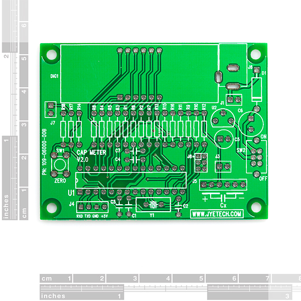
The instructions that come with it amount to "look at the markings on the board, and solder the parts in place". This might be a challenge for a first-time kit builder. Also the completed board has three empty resistor placements (R10, R17, R18), and three empty jumpers (J4, J7, J8). J4 can be populated with header pins or sockets for a serial I/O of the capacitance readings. I haven't tested that part yet. I suspect that J8 is a in-circuit programming connector for the ATMega (as it's a 6x2 pin connector near the ATMega).
Resistors R9 and R11-R16 are marked with five color bands rather than the more usual three plus tolerance. I'd never worked with that before, but with this page it was pretty easy to figure out which resistor went where:
http://samengstrom.com/nxl/10116/5_band_resistor_color_code_page.en.html
The instructions don't tell you the color codes for the resistors. If you can't figure it out, just post your question here, and I'll try to get back to you. If it's a problem, I'll take the time to post them here later, but I'm a bit busy today.
Similarly, two of the capacitors are polarized (the cylindrical blue ones), and there was no marking on the board to indicate which way they were to be mounted. I used the schematic, and apparently got it right. Both of them go with the negative side facing towards the slide switch (SW2). Maybe they'd work just as well the other way, but this way worked for me.
I found some of the colors hard to distinguish from one another. They blend with the darker body color of these resistors and the paint isn't the greatest. An ohm meter sorts that problem out pretty quickly though. I can't imagine building a capacitance meter and not yet possessing an ohm meter. Get the ohm meter first, it's more important.
Oh, I forgot to mention this - I had to grind down the two hold-down pins on slide switch SW2 to get it to mount flush on the PCB. They were too large for the holes they were meant to fit into. I just gave them a few seconds each with a stone grinder wheel on the Dremel to make them narrow enough to fit.
You could remove them entirely, I suppose - the switch is held down by six solder placements, and probably isn't going anywhere.
I was watching a movie in the livingroom while building and didn't want to go to the garage for the dremel. The pins are flat and I found that squeezing them in a pair of pliers I was able to just slightly curl them. that also makes them fit.
Fantastic stuff! This went together in less than an hour and worked perfectly on the first try. Though I have a really nice DMM with capacitance measuring, this unit is much more convenient to use. Powering it was a cinch - the barrel jack connector is the same size and polarity as Arduino, already have a ton of those around.
My only beef is that the LED display isn't very legible on a well-lit bench. Overlaying a piece of tinted/smoked acrylic should take care of this. Overall, an awesome deal at only nine bucks.
Has anyone checked if this fits in an Altoids tin? Looks real close, but I don't have one handy.
I put my empty board in a Penguin mints tin, pretty much the same thing as an Altoids tin. It just barely fit, if you use a 9-volt the battery would definitely have to be external. Maybe you could do something with a stack of coin cells to make it work internal. I don't think it would be worth it though, too expensive. I think it will fit the same after I stuff the board. I haven't tried that yet as I'm waiting until I can get out to pick up an IC socket and some headers.
It does in fact fit in an Altoids/Penguin mint tin. A 9-volt will not fit in the tin with it though. One of those little 12 volt camera batteries might though if you can get/build a very low profile holder for it.
FYI: Right after I finished soldering everything together, I tested the kit with some low pF capacitors and got funny readings. The next day everything was working fine. Maybe a thermal issue with a board warm from soldering?
I took a commenter's advice and replaced resistors 1-8 with 220 Ohms and the brightness of the display is perfect. However, the accuracy of my device is not. Measuring a 470u capacitor gets me (at best) a reading of 510u. Are the resistors possibly effecting accuracy?
October 8th, 2013 I just bought this kit. It was easy to assemble, and started to function immediately. I was very pleased until I really tried to check the display. The values displayed are about ten times the real value, and varies continuously. I triple checked the assembly, and the proper resistors are in the locations described by the BOM. but still no luck.
UPDATE: It is now working as expected. I am not sure what happened.
Took me about an hour to put this kit together and had no left over parts. A DVM is useful for checking the values on the resistors because the bands can be hard to read on them. Tested using my bin of random caps and it seems to work ok. It took me a few tries to realize that the J5 connector is split in half. For polarized caps, the positive lead goes into one of the three holes on the left side and the negative lead goes into one of the three holes on the right side. Larger caps with thick leads may not fit into J5 though. Pretty fun kit to put together.
kit went together easy enough after reading the comments here.. My only issue with it is that it outputs values with no decimals(is this on purpose or is it a mistake/defect/oppsmybad ???). If it is a mistake on my part, does anybody have and idea what resistor and what pin I should be tracing to find it?
I am also finding that I wish it would measure above 500uf - I got a lot of bad mobo's and LCD's laying around that I want to test caps from!!
I used mine to measure some 820 uF caps and was able to get readings that were pretty close to the nominal value of the caps.
Is it possible to get this to read in the 0.1 pF range?
(Please excuse multiple posts, Opera is not playing well with the site. And cant figure out how to delete a post.)
(Please excuse multiple posts, Opera is not playing well with the site.)
Has anyone been able to get the serial output from this? I've been trying with an Arduino Uno, but been getting gibberish.
Are you using the correct baud rate? Most work at 9600 but this outputs at 38400 so see what it is and change your code accordingly and it should work.
I built this capacitance meter kit, and it works great, the only thing I had a problem with was some of the resister codes were 5 band codes. I have a free Android tablet APP called "Arduino Companion", witch has a resister code calc that works great.
Though this was easy to do learn how to do. if you were able to attach meter leads, thatd be awesome. http://www.youtube.com/watch?v=uskvlG5d734&list=PL99E5146589FCE4E0&feature=plpp_play_all i made a video on how to put it together.
agree with everyone else before me - this is a fine kit. Assembled in under an hour, worked first time with careful soldering.
Have a magnifying glass to read the resistor-bands, and heed the instructions that say "install only parts listed on BOM". Works well. Happy with this purchase
Just arrived, done building, about 1 hour. Testing my stock of new and used caps. Appears to be a fine meter. New caps reading within tolerance. Very satisfied, will be using this to test motor caps. This was cheaper than any available over the counter meter and it has a wider test value range. How can you go wrong!!
Extremely "alpha" open source replacement firmware:
https://github.com/cstratton/atmega_capmeter
I believe the getting stuck in calibration mode occurs if it can't get a consistent reading. Mine worked fine right after assembly, but then I tried to do some flux removal after which it would get stuck in the calibration. My guess is that I introduced some micro-ampere leakage paths through plaques and/or moisture left behind by the cleaning. Substantially more scrubbing and more drying time and it was back to normal. Regardless, the circuit and basic theory is simple, so I traded out the supplied atmega48 for a bootloader-equipped atmega168 and am making progress towards a replacement open firmware.
Ok ... Gone to see on jyetech site. Looking at picture ... http://www.jyetech.com/Products/CapMeter/060_1.jpg
R18 R17 R10 not mounted ...
Also changed R11 (because was open !?!) to 2.7 M (3.3 M, but I had nothing else). Seems now to be ok.
Anyway, listing software might help (adding some tests before launching program).
Finished building Cap meter kit.
R10 not mounted as stated by GreyBadger (some two problems). Display is 3010 then runs (sometimes not)a few seconds then locks ... Pushing Switch display C0 ... no return or change ...
Any idea ... without software listing ?
Noticed, mine did not come with connectors like what is in J3? They are clearly shown in the pics, but I got none?
What are they called?
Thanks
Richard
They are "JST Vertical Connector - Through-Hole 2-Pin"
Sparkfun has a Right-Angle model that you might be able to bend the leads to make it vertical.
Just finished this kit (v2.0). As previously stated, it's pretty straightforward and can be put together in a few hours. Being it's my first kit, I had to throw this review together.
I swapped the 1.5k resistors for 681's for a brighter display. Not being an electronics guru, I chose these instead of the lower ones out of power concerns and lcd life expectancy. For power, I used an old wall wart with a 9vdc output and 750ma.
First time fire up-awesome! It worked! I checked it out on a Turbo200 multitap cap with 2,5,10,20 mfd ranges(I'm an AC mechanic by trade), it measured within expected range, although I have to say that if the readings are correct, these are very sloppy/loose readings for such an expensive device ($80.00us). Preliminary tests on smaller caps (electrolytics in particular) give mixed results. Polarity? Bad connections? Will check it against a new, off board cap soon. I don't like the test lead connections, and will soon remove the little terminal bar in favor of soldered on leads.
Another little item that I noticed, the board starts throwing up erroneous numbers 10-15 seconds after clearing in the pf range. Is this a concern, or is it simply picking up something closeby (cf lamp)?
Bottom line-great idea for a gift to a bright young one this year!
also on my readout it comes up looking like 244n what is the n?
"p" --- pF
"n" --- 1000pF
"u" --- uF = 1000000pF
Great tool, as I use it to check outboard motor condensers from as old as 1914 thru the 1970's. Thought it did not work when I first built it, being my first ever project like this. Called a guru and he helped me check everything on the board, and all of a sudden it just lit up. we determined it takes a while to "warm" up the stuff before it will actually work. I run it on a 9 volt battery. Does this come on immediately when hooked to wall outlet?
not very legible
Can we have this back at the original $8.95 price please. I was shocked when it came back into stock $5 more than before.
guess me eyes are tripping me up, a meter shows they are correct resistance. my mistake
my kit came with 3 10k R's, versus 2, so i'm missing the 120 R for R9. not a big deal.
and for R11, the color bands on this R is [orange,orange black, green, brown], which equals [33M 1%t], not 3.3M as noted in the spec sheet. my eyes could be tripping me up though. ;-)
cap meter v2.0
I have a display problem too. The 5 volts is around 3 picks up to 4 then drops back 3. The regulator is ok but it seems the display is not working as it should. The top left leg in each digit does not work. Also the 10 mfd cap gets hot. I think the
ATmega48 may have a problem. I have triple checked connections and components and can't find any problems. Does any one have any suggestions as to what to try? Thanks in advance...
fatcat
is the 28-pin socket for this a standard 28-pin? never used a atmel chip before. before i head to fry's wanted to be sure what to get.
I've been using this meter for about a year now and I wouldn't be without it! I did decrease the LED segment series resistors to increase brightness.
As the instructions are minimal I have created a page of instructions which also shows how I mounted the meter in a plastic box. See http://www.radiowymsey.org/capmeter.htm
Charlie.
Mine won't work. Busted display, I guess. Only a few segments flickering randomly. I measured resistance and double checked everything. Strangely, I get a short to ground on pins 8,9 and 10 of the display. Could someone check this and let me know if they get the same results (pin grounded on display)?
Even though it looks like you're missing some resistors, it doesn't seem to matter if R17 and R18 (10K ohms) are there or not but if you install R10 (330ohms) will keep it from working, it will be stuck with CO showing on the led array. The picture of the assy above is correct. Other than that, it works pretty good!
Just ordered this as some birthday splurging and I can't wait to get it to start checking the box full of caps I have.
As other commenters have said, are there any other betters way to make a case for this besides mint tins? Would be interested to know, if not I'll make my own and post it on here.
Great kit. I hadn't soldered in 5 years or more and this took maybe an hour to build. It worked right away off of a 9v power supply I had laying around.
Comments about the LED display are correct - it's bright but is hard to read in a well lit room. I am going to try the suggestion of putting some tinted acrylic over it.
Would like to see other builders' suggestions for an enclosure (besides candy tins). The instructions recommend a metal box.
This is an excellent project. It has autoranging. I use it all the time to verify capacitors.
Anyone know if a different color display will work?<br />
This one is what I'd like:<br />
http://www.sparkfun.com/products/9481<br />
<br />
Suppose it's cheap enough to get it and try! I'll report back.
We don't make this product in-house so we aren't really sure about the design and if different displays will work, sorry!
Great item, accurate. Replaced the current limiting resistors for the display though with lower values, as it was quite dim.
Found problem : - don't install R10 (330)!
Can anyone explain what R10 is there for?
Other than that, excellent device reads with in that measured on a calibration bridge!
Good down to 1p
Recommend it for any tech bench
Hi,
Just finished building kit! Three resistors were missing!!
When switched on it displays "3010".
When Zero pressed "CO" stays on permanently.
I've checked (and some again) the board for errors.
All voltages seem to be correct.
Processor must be working because zero switch worked.
Any suggestions?
Nice kit at a good price that went together pretty easily. DMM helpful on the resistor values. As noted, the display is dim and I should have used lower value resistors for the LED display as suggested by another commenter.
Thanks. Unfortunately we don't build this, so cannot change the kit contents. It is noted that the display is dim and 220 ohm resistors brighten it up.
I'm interested in the source code for this, particularly as a learning exercise. I emailed Jyetech and they said it's not available. However they said it's simple, "It was based on RC charging time measurement. Charging / discharging was controlled by making associated MCU ports HIGH, LOW, or High-Z."
There is this Arduino tutorial that looks like a starting point: http://arduino.cc/en/Tutorial/CapacitanceMeter
Anyone interested in trying to write new firmware for this? I'm considering using a atmega168 (or even 328) with the arduino bootloader.
--Rob
If you do try to make this thing into an arduino, be sure to replace the 12mhz crystal with a 16mhz one, or things might not work quite right.
I accidentally damaged the chip on mine and unfortunately couldn't get a replacement with firmware here. SparkFun recommended I contact JYETECH which I did. They were prompt and offered the hex file to me or purchase a replacement micro. Soon I'll have my meter back. :)
This is an awesome kit and useful piece of test equipment. I've reviewed and taken some action photos and video here: http://tronixstuff.wordpress.com/2010/03/20/kit-review-seeedstudio-capacitance-meter/
I just finished a v2.0 revision of this kit, and it works like a charm. It wasn't too difficult, although some of the through holes are pretty close together. I did have to double check the picture for the proper direction of the electrolytic caps. Also, I would have felt better if the kit included a socket for the MCU, rather than soldering it directly to the board...I'm not sure how heat sensitive those MCUs are (but hey, those sockets are cheap, so get your own!).
I have to say, I was pretty impressed by the options this meter comes with: 2 ways to power it with a wide range of accepted voltages, and besides the display, there's that serial pinout on the lower left you can attach pins for. I think it would actually work with one of SFE's serial-enabled displays. The kit uses 38400 bps with a format of 8 data bits, 1 stop bit, no parity. Has anyone played with the serial functionality?
Forgot to mention: Do bring a multimeter to check the resistances. Some of the bands are indeed hard to make out.
Is the firmware available for this and is it open source where we could see the code?
I left mine for a few hours, are there any guides to troubleshooting this? I haven't seen anything here or on the manufacturer's web site.
How long should the kit sit at 'C0' when zeroing it out for the first time? Mine has been sitting there for a while now...
Mine probably took somewhere between 5 and 10 seconds at the most.
Hmmm... I don't suppose the processor upgrade would do much good while still using it as a capacitance meter but maybe it could be swapped with a new ATMega 48PA to get a longer battery life.
FYI: According to the instructions you have to mount this in a metal case and connect the case to ground if you want to be able to measure down into the lower capacitance range.
I was going to gut an old broken capacitance meter I have and mount this inside that case but it's plastic and the lower values are what I bought the kit for.
Tonight I intend to see if it will fit in a Penguin Mints tin (Like Altoids but caffeinated). I'll come back and post about that as they are the same size as Altoids tins and someone asked about those. Maybe I can fit a mint tin inside the old capacitance meter case...
I'm wondering... if I mount this in a box what's the best way to extend the "test socket" to the outside of the case. Two wires kept far apart? A small piece of shielded cable? I really want to be able to measure accurately down into the 10s of pf if not single digits. I don't care much about the upper end as I have a couple meters already for that although it would be nice if this can be one meter for all.
I still haven't chosen a case and my little 10pf capacitors measures in at 10.2pf consistently. Maybe I don't need to worry about a metal case after all. I like the little red SparkFun cardboard box. Maybe I'll just mount the board and batter holder to the bottom of the box (so the battery doesn't slide around on the circuit board) and be done with it.
Is it me or does that "14-pin ATmega48 microcontroller" have 28 pins?
Dug up the schematic! The display LED is <font color="#FF0000">red</font>.
no schematic? no board layout? what color is the led display?
Can we use any 9V power supply for this?