- Home
- Product Categories
- Arduino Shields
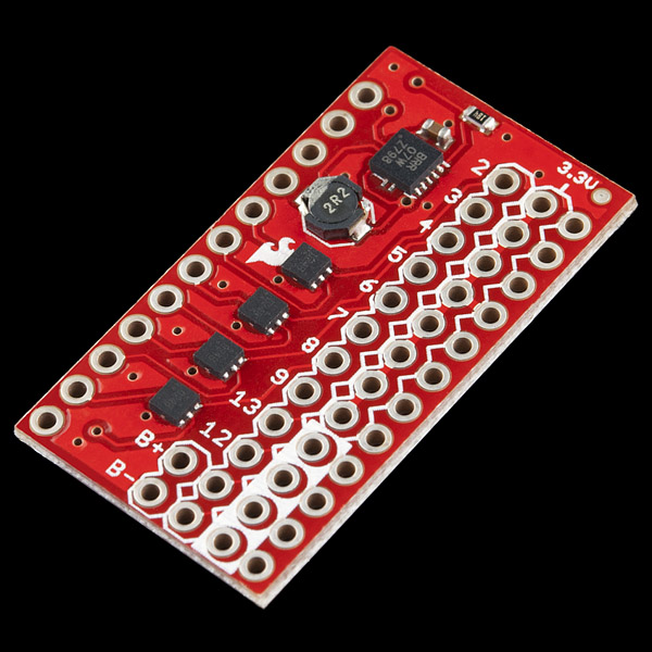
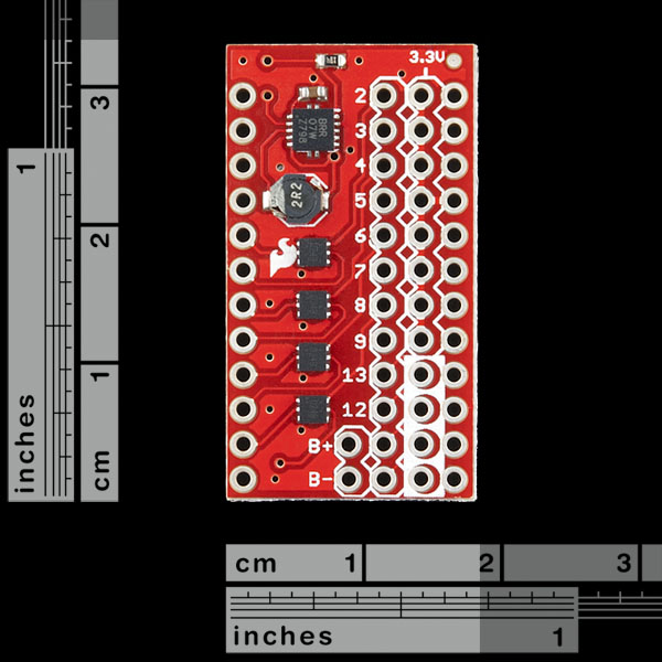
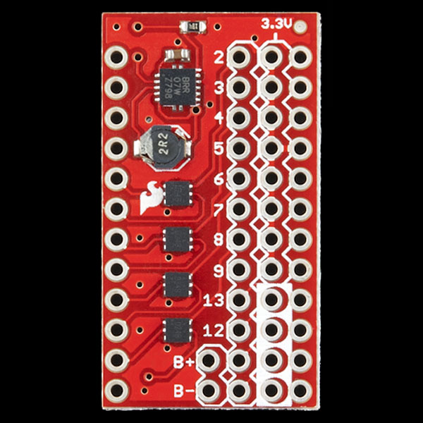
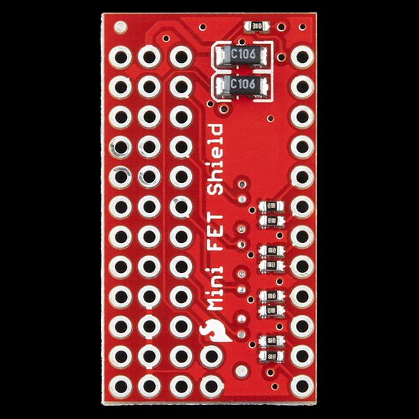
- SparkFun Mini FET Shield

SparkFun Mini FET Shield
Developed by Dave Vondle and IDEO Labs, this board is essentially the same as our Power Driver Shield, but the through-hole parts have been switched out for smaller SMD construction, allowing you to to drive high-current switches with your Arduino Pro Mini. This is a great shield for small prototyping.
Note: The power circuit chip is only rated to drive 0.6 amps. However, we've successfully tested it to over 2A.
- Schematic
- Eagle Files
- Hookup Guide
- Datasheet (FDMA1024NZ)
- Datasheet (TPS61200DRCT)
- IDEO Labs Page
- GitHub
SparkFun Mini FET Shield Product Help and Resources
Das Blinken Top Hat
January 22, 2014
A top hat decked out with LED strips makes for a heck of a wedding gift.
Core Skill: Soldering
This skill defines how difficult the soldering is on a particular product. It might be a couple simple solder joints, or require special reflow tools.
Skill Level: Rookie - The number of pins increases, and you will have to determine polarity of components and some of the components might be a bit trickier or close together. You might need solder wick or flux.
See all skill levels
Core Skill: Electrical Prototyping
If it requires power, you need to know how much, what all the pins do, and how to hook it up. You may need to reference datasheets, schematics, and know the ins and outs of electronics.
Skill Level: Rookie - You may be required to know a bit more about the component, such as orientation, or how to hook it up, in addition to power requirements. You will need to understand polarized components.
See all skill levels
Comments
Looking for answers to technical questions?
We welcome your comments and suggestions below. However, if you are looking for solutions to technical questions please see our Technical Assistance page.
Customer Reviews
No reviews yet.
Wow! Really? The hookup guide looks to be pretty darn clear to me. What do people need? Does someone from Sparkfun have to show up at their door and hold their hand? Sheeesh!
I'd love to see usable documentation for this product, since it's a much-needed non-Uno shield.
Some basic questions with no obvious (spelled out in the product description) answers:
In what orientation does this mount to a Pro Mini?
What is the pinout for this product? (It's ambiguous and time-consuming to try to match the schematic to the product, and not everybody wants to open up Eagle to figure out how the schematic and the board match up)
What, exactly, is different between this product and the IDEO page you link to? I appreciate you linking to inspiration/designer's page, but in this case the ambiguity between what this does and what the IDEO item does is unhelpful.
While I love the idea behind this product, it's by far the worst-documented and most time-consuming thing I've ever purchased on Sparkfun.
I completely agree. I have purchased several of these, but it is impossible to understand the pin out without recourse to the Eagle files. At least I hope they will make things clearer. I don't have Eagle installed so I haven't had a chance to check.
SparkFun should be ashamed about situations like this.
Any more news about these? It seems like maybe this is an orphaned part since I've been looking for this EXACT thing for about a week or more and I'm on this site every day. I found this in a post on arduino.cc.
I have a need for an LED controller board with maybe a few inputs.
I first thought
My big questions are I guess this is for a 3.3v pro mini and what are all those pins for? Like why a row of 3.3v headers? There is a jpg posted here but the link is dead.
Is this at a 5v or a 3.3v Logic Level?
Can anyone tell me how I might interface this with an Arduino Fio (connected to 3.6V LiPo) and a motor (requiring 3.3V, relatively low current)??
The lack of any manual is disheartening...
Yes, there really ought to be a complete pinout of this thing.... the datasheets and schematics tell you nothing.
Hey, I just wanted to add a protip for people worried about the 0.6A number. The 0.6A limit is only for the power supply which could just be used to power the Arduino from a Li-Po source. If you need to drive a lot of current, don't use the regulated power. For instance if you need to run a high power motor, connect one side directly to the battery or power source and one side to the FET (the inner row of holes). This configuration will allow you to drive something like 5A or more if your frequency is low (check the datasheet for details).
If I am driving a load less than .6A, I use the power supply to keep the supply constant so the voltage doesn't drop as the battery loses charge. This helps with LEDs because you can notice a brightness difference with a slight decrease in voltage.
Oh, and if you want a diagram of the connections head over to the IDEO Labs page linked above. Everything should be the same aside from the note: "pin that can be routed to pin 2" and the battery charger.
I'll check these comments every once in a while, so let me know if something isn't clear or if you have suggestions.
Hope you like it!
First of all, it should be stated in the product description that only 8 of the 12 pins are routed through MOSFETs!
Secondly... WOW it took me a while to work out how this is supposed to be used!
Turns out it is supposed to fit under/over an arduino pro mini (both facing up; so you cant see the handy silk screen anymore, or you cant access the reset button).
The pins are also wired in a kinda odd way if you ask me, but i suppose at least you get access to both GND and 3v3!
Also it would be nice for more info on the B+/- input in the product description! (ie: it gives 600mA of 3.3v from an input between 1.2v and 5.5v)
See here for a handy pinout (hopefully I got it correct!)
Any replacement link for the non-working one to the schematic?
Had to download eagle files to figure it out. The FDMA1024 will connect directly to the battery, so there is no need for a massive 3.3V strip. The 3.3v output route from the TPS is thick, however there is a skinny battery route, that does not make sense. I am using a 5V mini so I will have to change the TPS circuit to a output 5.5, by changing R3 from 180k to 100k.
There's no resistor for setting the minimun operational voltage (UVLO) on the TPS61200, that means that it is set to 250mV, That's a pity because LiPO and NiMH batteries whose minimal operation voltages are much higher than that cannot be safely used to power this board. A jumper with a resistor stair to choose UVLO between what's needded for NiMH, LiPO, and 0V would have made this board almost perfect.
The one thing that I would have added to it is a second battery step-up to get to 2A max output, which is what is needed to lift it from ground once you've added the arduino mini, few motors, battery, IMU and wiring...
Apart from cutting the VCC trace to the boost converter, what else needs to be done to run this on 5v? I love the design, but really need 5V due to the sensor input range in my design.
Thx!
the TPS6120 can be set up to operate much higher than 3.3V... LiPower can do and uses the same chip... Check the schematics of both and see what resistor has to be changed...
Just received mine and the supply only put out 0.6V. The "1Meg" resistor spot of the reference voltage divider has a 43K resistor. I replaced it with 1Meg and all is ok. I guess Sparkfun needs a visual inspection machine.
I'm interested in this because it's a small 8 channel fet. Is it possible to switch 12V LEDs with this, using a 5V or 3.3V Control? I'm not interested in the power supply/charging, or arduino mini parts at all, just the fets.
I'd like to use these in the same way. Does anyone know of any boards that can do this?
I finally got the schematic open (my problem, not yours) and it looks like maybe all the sources are tied to the Vcc of the charging circuit (so probably not 12V). I can't open eagle files, is it possible to just disconnect all the other stuff on the board and then connect my own 12V PS to the source pins? I'm trying to control one of those RGB LED strips with it.
This board is awesome. There need to be more shields for the Pro Mini like this. We use this board all the time.
I think the only suggestion for a version 2.0 that I have is to move all the PWM pins from the digital input section to the FET output. That way you can run 2 RGB LEDs instead of just 1. Otherwise you're wasting the PWM for no good reason. That said, having 10-12 all being input pins might be convenient for an input header
I don't think the description above quite does this board justice. It has an on-board power supply which will generate 3.3V from voltages as low as 0.5V. That means you can run an 8MHz Arduino off a single 1.5V battery!
I'd love to see a version of this shield with 5V output, and with the under-voltage lock-out set for LiPo batteries.
It should be clearly stated in the product description that the Vout on this board is set for 3.3v. If you are using this with the 5v Pro Mini w/ 5v peripherals, you will have to pass through the RAW and skip the shield's regulator altogether.
If you want to use PWM with the FETs, you can only directly modulate 4 of them (D3,D5,D6,D9). If necessary, you could wire across from D10 and D11 to use all 6 PWM channels.
Would I be able to use this with a 3.3V Arduino Fio, to drive 4 motors (requiring 0-3.3V inputs)?
I'm very happy with this. 600mw drives quite a few sensors! Very simple to use, pin high = power out on matching pin. No docs were needed (really wanted them) because it was so intuitive. If you don't want to cover your silkscreen put it on the other side of your mini! Future revision: Would be nice to push varied voltages out, contolling my 6v device directly off a secondary power source, but only when needed.
Thanks spark fun for all the inspiration!
Can I send it back for a refund if it doesn't work reliably at 2A?
I kindof agree with Josh,
I have a bucket of ESC with surface mount fets which can move 40 amps, The larger model is seriously old school, and this model is sub-amp.
Cool all the same.
Why such wimpy FETs? Surely you could use some higher current FETs so that, given an external power source, these could switch beefy current.
You should sell stackable headers for the pro mini.
4 six pins should work :)