- Home
- Product Categories
- Kits
- LED Cube 3x3x3

LED Cube 3x3x3
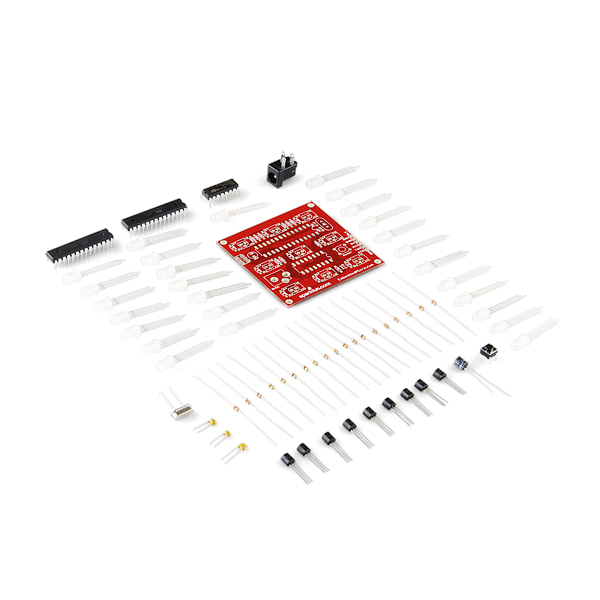
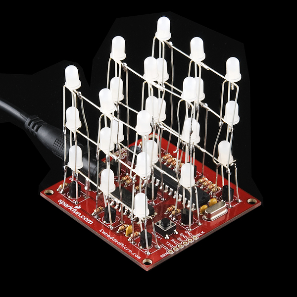
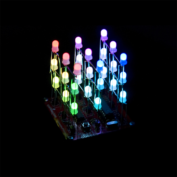
This is a kit for a 3x3x3 cube of RGB LEDs. This kit contains everything you'll need - 27 LEDs, an ATmega328 microcontroller, a custom PCB, and other supporting components.
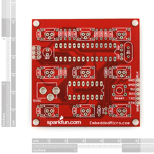
The included PCB breaks out the ISP header and the USART pins of the ATmega328; so you can customize the code and control it with a serial device. Sample code comes pre-programmed on the ATmega328.
New to this version of the Cube is the Arduino serial bootloader programmed onto the ATmega328. This means that you can easily reprogram the firmware, using either an FTDI Basic Breakout or FTDI Cable in conjunction with the Arduino development environment. When programming the cube from Arduino, select the 'Arduino Duemilanove or Nano w/ ATmega328' board option. Headers are not included for the 6-pin FTDI header, we recommend right-angle breakaway headers.
Power should be provided by a clean, regulated +5VDC source. A 2.1mm barrel jack connector is included, but the power supply is not. If you don't already have one, we recommend one of our 5V Wall Adapters. Stand-offs are also not included, but are highly recommended!
You'll need a soldering iron to put this together. All components are through-hole, but the LED matrix is a little difficult to assemble. Make sure you thoroughly read through the build instructions before you buy!
Note: We are now including lengths of wire in the kit, but you will need to strip it yourself.
Note: This product is a collaboration with Embedded Micro. A portion of each sales goes back to them for product support and continued development.
Replaces:KIT-09391
- 1x Atmega328 (pre-programmed, w/ Arduino bootloader)
- 1x 74HC238 - 3 to 8 Line Decoder
- 1x LED Cube PCB
- 27x RGB Diffused LEDs
- 2x 22pf Ceramic Capacitors
- 1x 0.1uF Ceramic Capacitor
- 1x 10uF Electrolytic Capacitor
- 9x 1kΩ Resistors
- 1x 10kΩ Resistor
- 1x 16MHz Crystal
- 1x 2.1mm DC Barrel Jack
- 9x 220Ω resistors
- 9x NPN 2N3904 Transistors
- Build Instructions
- Schematic
- Source Code
- Arduino 1.0 Sketch
- Embedded Micro Homepage (Programming Tutorials and more!)(YouTube)
LED Cube 3x3x3 Product Help and Resources
Core Skill: Soldering
This skill defines how difficult the soldering is on a particular product. It might be a couple simple solder joints, or require special reflow tools.
Skill Level: Competent - You will encounter surface mount components and basic SMD soldering techniques are required.
See all skill levels
Core Skill: Electrical Prototyping
If it requires power, you need to know how much, what all the pins do, and how to hook it up. You may need to reference datasheets, schematics, and know the ins and outs of electronics.
Skill Level: Rookie - You may be required to know a bit more about the component, such as orientation, or how to hook it up, in addition to power requirements. You will need to understand polarized components.
See all skill levels
Comments
Looking for answers to technical questions?
We welcome your comments and suggestions below. However, if you are looking for solutions to technical questions please see our Technical Assistance page.
Customer Reviews
No reviews yet.
I finished my cube tonight. This little kit is one that ranks high on the 1 to fun scale. It is really a neat little device.
The instructions need to be revised in my opinion because the parts provided do not correspond to the build instructions and the circuit board does not match the board in the photos.
I also did not follow the instructions on how to build the LED matrix. I think it is easier solder the lower plane to the board and then build up from there. I did use the suggestion on making a holder to place the three LEDs in for soldering together. I used a small box and made the holes in it. I built the bottom rows and put them on the board and tested each row as i built. Building it from the bottom up allowed me to test each row as it went on the assembly. I did manage to bend one LED wrong and testing each row allowed for an easy fix.
I highly recommend this kit.
I understand that the 3 to 8 decoder and the extra pin from the microcontroller selects 1 of the 9 rows of LEDs but how does it know which of the 3 LEDs in that row to select? I apologize for the trivial question but my friends and I have been analyzing this for some time and we're still scratching our heads @_@.
This appeared in my cart by itself! What is this sorcery?!
I try to build it by myself. But the program goes too fast. Can yo help me? Please
Nice project , but the leds are poor quality . Mine's been running nonstop a bit over 2 years now , and now there are 5 blue leds that are broken . The good news is that the first blue died a short while ago , but the rest are following fast . I have not measured the current fed to the blue's but still i think it's just that the leds quality is not good .
I was looking for some help on how to modify the hardware and software of this kit to use a photo resistor to turn the cube on when the lights turn off while still being able to turn it off and on with a basic switch.
Just a heads up --- you will need to load the code via FTDI. It would not do squat until I did.
After that it was worth every penny!
My daughter loves this thing!
Could you (or anyone) elaborate on exactly how you programmed it via FTDI? I'm inexperienced and not having much luck. Any help would be appreciated!
PM me if you still need help with this
Although the build instructions indicate headers are optional and only necessary if you want to reprogram the cube I had to load the main.hex from the source code file myself - so probably a good idea to order some headers with this and plan to program it.
To program the cube with an FTDI cable over USB using the linked code you can use avrdude. Get WinAVR (it comes with avrdude) and install that. Then you'll run a command like this in the directory that has the main.hex file (from the source code link).
(Replacing COM5 with the appropriate port.)
I just have a question, does the ATMega is already program or not?
Just finished my cube. As the other comments have said, the instructions for construction are out of date, but honestly the PCB is labeled very well, except for the polarity of the drum capacitor (yes that's a negative sign). The instructions for assembling the LEDs are still very helpful. Overall the kit was very fun.
Note for anyone who, like me, buys the FTDI cable for reprogramming, the distributed code is for use with AVR studio + WinAVR, which is not compatible with using the FTDI cable for reprogramming. When asking techsupport how they suggest to use the distributed code with the cube, I am told to use the arduino IDE instead of AVR studio.
We will be updating the instructions soon to reflect the new kit. An update for the code and instructions on how to program it through the bootloader will also follow.
A shield for arduino would be so much nicer for the more technically inclined. I ended up using the schematic and using a perf. board to wire it myself. I would much have rather have ordered a shield so I can do all my own programming from scratch. Or maybe a PCB with a header to connect up at free will.
This is an arduino with a full blown ATMega 328 that can be programmed with a FTDI friend or similiar. look on the bottom view left-bottom corner.
So I am glad I came here to read this, because I too was confused when I got the kit. There are more parts than listed in the instructions, and the PCB is not the same as the images. I started to assemble it when not on the net, and stopped because the instructions and parts did not match.
A few suggestions and comments
1). I agree, this kist is a bit over priced, and bending the LEDs is a difficult task. For the price of this kit, toss in an extra LED or two so we can make a mistake. (Thanks to the quick people at Sparkfun for quickly replacing a dead LED I received.)
2). Label the parts, or include a cheat sheet to tell us what they mean. They were all in one little bag and I have no idea what "5KM" means on a small cap.(Yes, I figured it out be elimination.)
3). Include documentation. A note that the drawings are wrong, that some parts have changed and why, and even some instructions, especially given that the on-line ones are wrong now would be welcomed here
OK, I carefully built the kit, I tested all the LED sheets before inserting them into the board, and all parts seem to be properly placed. I see no solder bridges, and it all looks good. But NOTHING happens when I power it up. Occasionally an LED might blink a color, but that is all. Could the ATMEL be bad? If so, how can I tell? I have debugged this as far as I can go and it is not working.
If you are not on the high end of kit building, you may want to PASS on this kit. I am an engineer, and I seem to have messed it up somehow (or received a bad part) But not sure how to know.
This is why we have tech support! Contact them at techsupport@sparkfun.com and they can help you out.
Thanks.I will report back when I hear something.
Ouch: One simple question asked and answered about every other day? This is going to take a long time to resolve. SIGH!
Emailing us generally gets you answers faster. We answer those before comments and unless we are really slammed with questions (like the month after Free Day), we have a fast turn around time.
can i use the 950nm LEDs on this kit? I do not need color.
Be careful to orient your stacks of LEDs correctly. Read the silkscreen carefully as it is correct. The graphic in the pdf instructions is wrong/outdated. I know because I mistakenly used the orientation of the "special led" to the crystal in the photo as a guide and got it backwards. No big deal, I learned how to desolder with a desoldering pump along the way.
While they suggest the 5V ac adapter, i have been running mine just fine off of 3 AA batteries. and while it will run noticeably dimmer i have encountered no problems running it with a 3V lithium cell, even those tiny 20mAh ones.
Or is there any kinda prescripted codes we can get to use?
Are these preprogramed to react to sound? Or would u manually have to do it via something like parallax? Im a SCADA student and looking for something to build for a Xmas break project. Thx
thanx but theres heaps of products listed under arduino..
is the UNO the one to buy? sorry but im confused.
after lots of reading am i safe to assume i need a uno board which will connect to my pc with a standard usb cable and i connect the led 3x3x3 cube to the arduino uno using the FTDI Cable 5V sku: DEV-09718 which is out of stock anyway so i cant purchase anything until it comes in..
also it says something about right-angle breakaway headers.is this to connect the ftdi to the led cube? thanx again for the help.
Swing and a miss. :-)
Contact techsupport@sparkfun.com and they can explain it all to you. In short, all you need is an FTDI basic, or an FTDI cable. The LED cube is essentially an Arduino itself.
i just saw this-- LinkM - USB to I2C, can i use this to program the led's?
Use and FTDI basic (or similar) and program under the Arduino IDE (www.arduino.cc).
hi i havent built a kit for 20 years but stumbling across these awsome led cubes has made me want to build it. before i order the kit can you guys please tell me exactly what else i need to order to program it from my laptop? its a bit confusing to me but will that USB-TTL cable be enough and then i just download the software and thats it?? sorry for bein such a F*CKN NOOB
Use and FTDI basic (or similar) and program under the Arduino IDE (www.arduino.cc).
The first image shows two 28 pin dips. A yummy prospect if there is an additional piece of hardware included ;)
Where is the 10K ohm resistor used? It is not shown in the schematic.
KIT-09391 used 3x 200 ohm, 3x 169 ohm, and 3x 100 ohm resistors. Where this kit uses 9x 220? resistor. Are there changes made to the code to compensate for the new values?
Sorry but the picture is a mistake, you only get one AVR.
That schematic is outdated. I'll see if I can get them to update it. The 10K resistor is a pull up on the reset line of the AVR.
The LEDs used were changed and they are more ballanced than the old ones so the resistors of the same value can be used without having red over power the other colors. There are no changes to the code.
I have a question about how this works. Please bear with me here as I am a bit of a noob in electronics. I do not expect a detailed answer explaining the whole schematic. A short answer would be helpful.
How does the ATmega chip control the output of 27 LEDs? I mean I know it does not have 27 output pins, but I'm guessing that (3-8 line decoder) converts 3 of ATmega's pins into 8. Is that how it works? Am I even close to the right answer?
The LEDs are multiplexed (google it). Basically each one is only one for a short amount of time. The 3-8 decoder is used because only one of the 9 LED rows (one extra pin from the AVR is used for the 9th one) are ever on at the same time.
Why is this kit so crazy expensive?
Look at the price of the RGB LEDs. Add that to the price of a bootloaded ATmega328 and a couple bucks more for all the other components, and the PCB, and its actually not a bad deal when you add it all together.
Hmmm... if you get those LEDs individually it's nearly $50 for 27 - but there's a pack linked down there with 25 of these guys for $20. Maybe this kit's price should be reviewed?