- Home
- Product Categories
- Arduino Shields
- SparkFun USB Host Shield


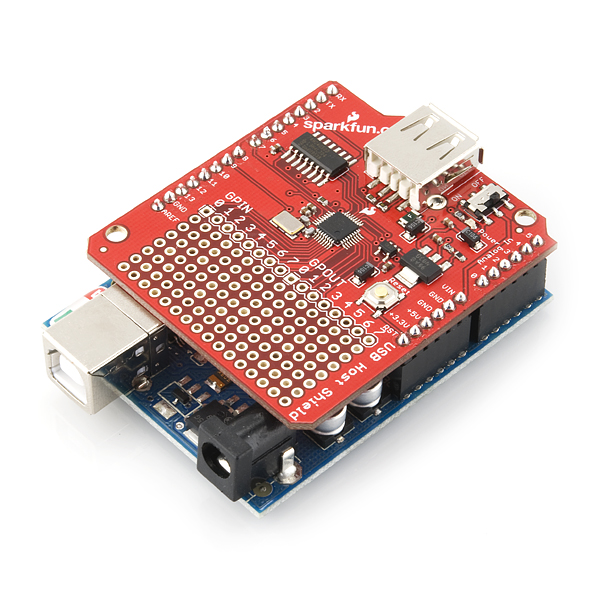
SparkFun USB Host Shield
This new version corrects the pin out for the GPX and RESET pins. The SparkFun USB Host Shield contains all of the digital logic and analog circuitry necessary to implement a full-speed USB peripheral/host controller with your Arduino. This means you could use your Arduino to interface with and control any USB slave device - thumbdrives, digital cameras, bluetooth dongles, and much more!
A four-wire serial interface is used to communicate with the host controller chip, so the shield connects the Arduino's hardware SPI pins (D10-13) to the MAX3421E. A USB type A female connector is wired up to the IC, and it also supplies 5V as any normal USB port would.
The Host Shield takes its power from the 'Vin' pin on your Arduino. Power from that pin is regulated to both 5V and 3.3V on the shield. All SPI signals are sent through a hex converter to step them down to 3.3V.
- Schematic
- Eagle Files
- Datasheet (MAX3421E)
- GitHub Hardware Repo
SparkFun USB Host Shield Product Help and Resources
Output Error
If the output on the Arduino serial monitor is showing:
OSC did not start
it's possible that there is something with the configuration of the library and the microcontroller that you are using. Try checking the connections and making sure that the shield is connecting to the correct ICSP pins http://hardwarefun.com/tutorials/using-usb-host-shield-with-arduino#comment-34681. A customer received the error on their Arduino Mega2560 but not on their Arduino Uno.
There was an old post in some comment about needing to change a library file but I think the updates in the code make it not necessary after a certain Arduino IDE version. The customer was able to get it working by changing the #define USE_UHS_MEGA_ADK in the settings.h file of the USB Host library.
Core Skill: Soldering
This skill defines how difficult the soldering is on a particular product. It might be a couple simple solder joints, or require special reflow tools.
Skill Level: Rookie - The number of pins increases, and you will have to determine polarity of components and some of the components might be a bit trickier or close together. You might need solder wick or flux.
See all skill levels
Core Skill: Programming
If a board needs code or communicates somehow, you're going to need to know how to program or interface with it. The programming skill is all about communication and code.
Skill Level: Competent - The toolchain for programming is a bit more complex and will examples may not be explicitly provided for you. You will be required to have a fundamental knowledge of programming and be required to provide your own code. You may need to modify existing libraries or code to work with your specific hardware. Sensor and hardware interfaces will be SPI or I2C.
See all skill levels
Core Skill: Electrical Prototyping
If it requires power, you need to know how much, what all the pins do, and how to hook it up. You may need to reference datasheets, schematics, and know the ins and outs of electronics.
Skill Level: Rookie - You may be required to know a bit more about the component, such as orientation, or how to hook it up, in addition to power requirements. You will need to understand polarized components.
See all skill levels
Comments
Looking for answers to technical questions?
We welcome your comments and suggestions below. However, if you are looking for solutions to technical questions please see our Technical Assistance page.
Customer Reviews
3.6 out of 5
Based on 13 ratings:
1 of 1 found this helpful:
Works very well
Works very well. My only qualms: 1) It takes a bit too long for the connection to take place when a usb device is connected. Maybe I need to mess around with the settings more. 2) I wish it worked with the Leonardo out of the box. Had to solder a few jumpers.
1 of 1 found this helpful:
Board is still not up to spec
The version I got has to have a jumper installed from D7>RST in order to work with the XBOXUSB function from USB2.0.
I don't see anything on the board showing which build version of it I have so I don't know if this was old stock or the redesigned one. It seems to work OK with the jumper in place but that means I have to solder something else in place or not use the stackable headers I put on (easily anyway). When you say it's the same thing (USB host shield) it should be built to match the specs of the Arduino version so that it doesn't have to have this jumper added to work.
1 of 1 found this helpful:
Works great with Wii controller when jumper added
The working configuration I am using is: Sparkfun RedBoard.... USB Host Shield with jumper from pin D7 to RESET.... Bluetooth USB Module Mini..... Wii library from link below.... https://github.com/felis/USB_Host_Shield_2.0
Currently it pairs with the Wii remote and outputs the buttons pushed in a terminal!!
2 of 2 found this helpful:
Great product, just a little confusing with initial setup
Like others have mentioned, you need to jumper D7 to RESET and external power seems to be a requirement. After struggling through this and a few other problems that were my own fault this board is now working perfectly!
For anyone interested - I wrote up a quick summary on how to configure this shield. Probably not useful to the Arduino experts, but it's the kind of information I wish I had when I got started with this shield: https://joshcaplin.wordpress.com/2016/06/05/configuring-an-arduino-usb-host-shield-a-beginners-guide/
Got it to work with the Arduino Mega 2560 R3 and an XBOX 360 wireless receiver/controller!
To get it to work with the Arduino Mega 2560 R3, you will need to jumper the shield pins as follows... 11 -> 51, 12 -> 50, and 13 -> 52. Do not jumper shield pins 9 or 10! These are hard coded in UsbCore.h as INT and SS respectively (line 45).
I don't have it yet!
Haven't received it yet!
Looks like it should be arriving Wednesday 5/29/2019, by end of day. :-)
Won't work with Leonardo (or others) without lots of jumpering
This device uses SPI (as it says in the description.) The Leonardo does not connect its SPI pins to D10-13. Instead, like a lot of Arduino models, it has more pins so it pushes them off to an ICSP header. Since this header is in the same place on all the boards (certainly Uno and Leo), and that the board covers them up, it's a bit strange that this board chose not to use them instead. Since they're covered up, we can't reach them. (Another review mentions soldering.)
Basically, this board will only work out of the box with the Uno and Duemilanove (and maybe the Due? not sure)
Worked as Advertised
I fly wired it to an ESP32 module (Heltec ESP32 S3) I had to modify the following library files \Arduino\libraries\USB_Host_Shield_Library_2.0\UsbCore.h \Arduino\libraries\USB_Host_Shield_Library_2.0\avrpins.h \Arduino\libraries\USB_Host_Shield_Library_2.0\settings.h \Arduino\libraries\USB_Host_Shield_Library_2.0\usbhost.h Then, I manual Initialized the SPI Bus and it passed all tests. SPI.begin(48, 33, 47, -1); SPI.setHwCs(false); SPI.setFrequency(1000000); usb_revision = Usb.regRd(rREVISION);
Now, I need to read a USB Memory Stick (going to take a bit of code)
0 of 1 found this helpful:
not for Lenorado
spend some time try to figure out how to connect it with Lenorado board which is using the programming header, should have a better instruction to do that.
Aparently Shield can not be used as a serial Host
Apparently can not be used as a host serial port, per Arduino support. I GOT NO RESPONSE FROM THE SPARKFUN FORUM.
I connected it to a USB serial device (Victron BMV-12) that I've previously interfaced sucessfully to from a W11 computer. The BMV12 broadcasts a serial signal over a USB Type A male that I wanted to be read by an arduino Uno. I am an expert coder (but only middle Arduino coder) and hardware engineer.
a) No documentation on how to program this to capture a RS232 signal that is easily read by W11. b) NO SUPPORT from SparkFun, either directly or via the forum. No sample code, no directions on hardware jumpers. Yes I read Josh Caplin's blog, c) I'm totally pissed I wasted $53 (outrageous shipping cost) for this. Wound up building my own hardware interface. Duh. d) Wasted almost 3 weeks of my life trying to get this to work. Sparkfun is NO FUN. In contrast, for the other 6 modules I've built for this project, none took longer than a day to design. e) I'm sure you will not publish this review, but thank you for asking about my experience.
Review
Review from my technician I’d give it 4/5. This inability to use the Arduino’s on-board 5V regulator, and no indication that it isn’t present for low-current applications is a definite oversight.
My mistake
I messed up, did not notice it does not come with headers of any kind. No mention on the product description. Have to place a separate order just for the headers.
Can't get it to work with my Mega 2560
I've tried using a separate battery for the shield, connecting pin 7 and RST, and then connecting these pins between the Mega and the shield: 52->13 50->12 51->11 53->10
Still can't get this to work. I also pulled the shield off the Mega (which seems to defeat the purpose of having a shield...) and made the jumpers with it off the Mega. Still not working. Not sure where to go from here.
CP210 chip, Can we communicate with this board , with baudrate = 921600 ?
Hi there, it sounds like you are looking for technical assistance. Please use the link in the banner above, to get started with posting a topic in our forums. Please, clarify/elaborate on what you are trying to do in your post. Our technical support team will do their best to assist you.
I want to reiterate what solves a common issue with this board.
I was trying to simply interface a USB keyboard to an Arduino and having one weird issue. It would work on a RedBoard but not consistently. Randomly it would just stop working and swapping USB devices did not work at all. On an Uno I got the "OSC did not start." consistently. :@
PIN 7 of the Arduino is tied the reset pin of the MAX3421E. If this pin is not set to OUTPUT then it will drift causing the MAX3421E to reset at random. If you are using the USB_Host_Shield_2.0 code that everyone points to then this pin is not set by default. Simply put this code before Usb.Init() in your code and all your problems will be solved!
Can I connect this shield with the ESP8266 (i.e. Feather HUZZAH ESP8266)?
While I'm not familiar with the Feather Huzzah this shield give your Arduino all the power and responsibility of a host controller. This includes drivers. Any USB device can be plugged into this shield, but getting the Arduino to communicate with that device is not always trivial. If your project can not run natively on the ESP8266 I'd look into the ESP8266 shield, or even just interfacing the bare module over serial to your Arduino. If you have any other questions please feel free to email our techsupport department.
This board appears close-up in the Arrow episode "Second Chances" (season 5 episode 11) at about 29 minutes in. :-) Rotate your head about 150° for a clear view of the "sparkfun.com".
I want to send some data from arduino to computer using this shield. Do you have any hints or example how I can do that? There are many examples for communication with other devices like android but I can't find any with PC
I had an issue with unstable operation of this board + USB joystick + Arduino Uno. It worked for a while, then stopped. After some debugging with scope I realized that there is no 3.3V -> 5V voltage translation on MISO pin. * MAX3241 Voh = VL - 0.4V = 2.9V. * ATmega Vih = 0.6Vcc = 3.0V This board does not have to work with 5V Arduino boards. Adding LVC1T45 voltage translators between MAX3241 outputs MISO and GPX and Arduino pins D12 and D8 Seems to fix the problem. Schematic is here
I want an Arduino and an Android phone to communicate to each other. I bought the USB host shield, downloaded the library available at the link "Projects and Code", wrote an Arduino sketch and Android app according on what I found on the internet related to this issue. I found some compiling problems that got fixed thanks to the tips I found on the internet, but in the end, it doesn't work. Once the sketch is downloaded to the Arduino board and the app to my mobile Phone running Android 4.4.4, I connect both devices by means of a USB micro B cable, and nothing happens, when supposedly, this should fire the app start up. I don't see either any print out in the Serial Monitor from the Arduino side. Can anybody tell me what I am missing or send me to a proper forum?
I bought this board to use with a wired Xbox 360 Controller or Xbox 360 Wireless Adapter but neither of the two get recognized by the board. The only USB device that seems to get recognized is a Belkin USB WLAN dongle. I am using the board with Arduino Uno Rev. 3... What am I missing?
How do your boards solder so well? I seriously sling hot solder form across the room and your boards soak it up in the spot I wanted, what are you doing differently with the production these thru hole PCBs?
Nice shield. It tooks some times for me to find and fix an issue with USB host library running on UNO. Reset pin 12 of the IC on this board wired to dig. pin 7, and it looks like as another citcuitsathome 's board has reset tided up to reset of the arduino board, nobody care anymore about status of the digital pin 7. And of course chip is in RESET, because there is "0" - active at this pin. To fix, simply add two lines in your sketch setup(): pinMode( 7, OUTPUT); digitalWrite( 7, HIGH);
Thank you! Can't recommend your solution enough - worked perfectly for me!
Thanks. Its working now :D
What did you do to get it working? Just those two lines of code worked? Because it didn't for me
Thanks a lot for this tip. Very helpful !
Although I bought the latest USB Host Shield, I mostly had the "OSC did not start" message while trying the HIDkeyboard library. I added the following code in my "setup" function and now it works correctly :
(I found this into the USBH_MIDI library )
Ok it was explained here : https://github.com/watterott/KnowledgeBase/wiki/SparkFun-USB-Host-Shield
It should be noted in the description that the shield does not come with headers installed
I guess I have to solder the pin's to the shield myself
I have this shield (DEV-09947) and now need to use it with an Arduino Mega 2560. After reading various posts around the Net I'm still uncertain about the compatibility between them and if there is any change to put in the code for driving the shield with Oleg's library 2.0 (felis-USB_Host_Shield_2.0-96d506b).
Can someone shed the light for me?
I know this is late. I just got it working on a Mega2560 R3 with a transmorgi shied. I had to change the SS pin back to 10, but that was the only change. Also works with an UNO R3 without the Transmorgi Shield.
Will this play nice with the micro sd shield (http://www.sparkfun.com/products/9802) ?
Well just get the go-between-shield!
Unfortunately, it will not. There is a conflict on D8 between the MicroSd Shield's CS pin and the Usb Host Shield's GPX pin.
Seems to be the story of the Arduino - everything wants to use pin 8 or 10 (or both), then SPI across 11-13 - unless you want to roll your own.
Hi,
I just got this Shield.
Like some of you, when I tried to execute the board test sample I got the following error :
Error: OSCOKIRQ failed to assert
Circuits At Home 2010
USB Host Shield QC test routine
Press any key to continue…
Reading REVISION register…Die revision invalid. Value returned: 00
Test FAILED!
Test Halted.
0×55 pattern is being transmitted via SPI to aid in troubleshooting
Press RESET to restart test
I’am using USB Host library downloaded with the name felis-USBHostShield-a59ba5b.zip.
I tried to change MAX_GPX and MAX_RESET to #define MAX_GPX 7 #define MAX_RESET 8 but problem still persists.
I use an ATMEGA 2560 linked to my PC and an external +9V power supply.
(SPI pins are correctly connected according to atmega2560 specification)
Thanks for your help !
I found the solution, just redefine the MAX_SS constant to 53 after that all tests passed !
Here is a part of MAX3421e_constants.c:
#if defined(AVR_ATmega1280) || (AVR_ATmega2560)
#define SCK_PIN 52
#define MISO_PIN 50
#define MOSI_PIN 51
#define SS_PIN 53
#endif
#if defined(AVR_ATmega168) || defined(AVR_ATmega328P)
#define SCK_PIN 13
#define MISO_PIN 12
#define MOSI_PIN 11
#define SS_PIN 10
#endif
#define MAX_SS 53
#define MAX_INT 9
#define MAX_GPX 8
#define MAX_RESET 7
My power LED does not turn on when power with a 9-Volt source or via USB. I have voltage at Vin, I have voltage on the other side of the switch when switched on. It looks like the LED might be installed backwards. Anybody else having this problem?
Just the same problem (=
I just got this board and can't seem to get it to work. I am using Oleg's code and receive this message: "Error: OSCOKIRQ failed to assert" I am using the Mega 2560 with an external power supply. I have read everything I can find about this and have tried everything suggested, but no luck.
The SPI pins are located somewhere else on the arduino mega, so this shield will not work out of the box. You need to do some soldering to get this to work. Just google for arduino mega and SPI.
I have a Duemilanove board and this shield
To get V2 of Olegs code to run I must solder a line from reset to D7 on the sparkfun board. The code relies on reset commands coming from the arduino and on the Sparkfun board reset is not connected to the shield
This shield will not work with Arduino Mega, since mega uses different ICSP pins. This shield has ICSP routed to SS-10 MOSI-11 MISO-12 SCK-13 while mega uses 53 51 50 52 respectively, so to get it to work with mega you will have to make changes in hardware accordingly.
unsure if this has been asked, before and I missed it below, but is there a mini version to the USB host shield? I'd like to interface it with an xbee-R shield and a pro mini, and a 360 controller for a quadcopter RC build...conceptually, is that doable? without something so...bulky? :)
We don't carry a smaller one, but check out Oleg's site, I believe they do.
Can I use it to communicate Arduino Leonardo with an Android tablet. My tablet only has mini USB connector. I would like to control the tablet with the arduino.
You should be able to (take into account any pin changes between the Uno and Leonardo). But there are probably easier ways. With the USB host shield you basically end up having to find or write drivers for your device. A couple of other thoughts... If your tablet supports USB OTG use it, it will turn the tablet into a host, with a USB OTG cable you can then connect the Leonardo and the tablet will basically act as a computer. Or try Bluetooth, the tablet most likely has Bluetooth, get a Bluetooth module for the Leonardo and send commands to the tablet that way.
Hi, I bought a board last week. To give it a kick start I downloaded the library USB_Host_Shield_20. When I compiled the code board_qc, to check the board, it gave me several errors:
Anyone have any idea on how I can get rid of these issues? I'm using an Arduino UNO board. After these errors remove I can start with connecting the board.
It seems that these functions are not getting recognized. This might be because some missing header files. I believe if I include one or more particular header files which define these functions then this would work. Can someone tell me what is/are the header files I need to include?
Is it possible to use USB Host Shield together with CAN-Bus Shield ?
hello, my shield is not working anymore and the MAX3421E chip gets really hot.. what could be the reason?
I investigated a bit and noticed that the 3.3V on board regulator is actually outputting 4.2V instead of 3.3V! what could be the reason??
just a stupid but important for me question where can i get the exact pin configuration of this board? the links given here seems to be for a board having a different layout than this one
Does this works for the mini arduino pro?
Could this be used on a Mega so that instead of using the Uno's D10-13 pins to uses the Mega's D31-34?
Is this compatible with Arduino Mega?
Hey everyone I tried running USB host shield by Sparkfun on Arduino Mega. I Updated the libraries by changing
define SCK_PIN 52
define MISO_PIN 50
define MOSI_PIN 51
define SS_PIN 53
also changed
define MAX_SS 53
But still I'm getting Error: OSCOKIRQ failed to assert. Can anyone help me with this. Thanks in advance.
Shield works great! A couple tips to help others avoid the stumbling blocks I hit:
(1) You really do need to jumper the RESET pin to 7. Sounds silly, but if you're seeing "Error: OSC Did Not Start" or a variety of other errors, this is your fix.
(2) For my application, I was using a mouse with a 1ms poll rate. The Host Shield Library (v2) has a default 10ms delay between polls. That sucks! To fix it, I edited "hidboot.h" in the library. Near the bottom of the file, look for "qNextPollTime = millis() + 10" and change the 10 to a 1.
(3) Not all the mice I tried played nice with this shield. The Razer Taipan is the one I ended up using. It has an absurdly high DPI and AWESOME drivers that you can use to tweak firmware settings like DPI and liftoff distance. The taipan is pricey, though -- if your application doesn't require these things, try something cheaper first of course.
Happy hacking!
I have tried using USB host Shield with Arduino uno with a joystick. But I'm getting an error Data Packet 9. Can anyone suggest me why this error is coming?
I was not able to get Oleg V2 library to work on the shield until I put the jumper from D7 to RST. Initially, hesitated to put the jumper, but after I read all the comments and I looked at the schematics. I realize that Oleg V2 Library should be resetting the RST line if it is not using Pin D7 to do the job. But make sure you do not connect the D7 on the shield to the Arduino. You only connect D8-D13 to the Arduino, otherwise you will be shorting the Arduino D7 to RST. If you set Pin7 as output and high, this should also prevent Pin D7 from resetting Arduino (if D7 is still connected between Shield and Arduino).
I got the shield working with a PS3 remote using a usb cable and all readings are fine. How ever when I connect a usb dongle that came with a bluetooth mouse I bought there is no connection between the two. The mouse on the other works fine.
Do I need to buy a new usb dongle for the shield to comunicate with the PS3 remote?
Do you mind sharing with me how you got this to work? I'm having troubles getting the PS3 controller to output anything.
Hey guys,
I'm playing around with my new USB Host Shield and have encountered a problem. I am simply connecting different optical mice to an Arduino Uno through the shield. I have got 1 (let's call it mouse A) up and running. It displays right/left/middle button presses and delta x's&y's for movement. I have a second mouse (mouse B) with the buttons working, but I cannot get the movement to display. On a guess, I probed my USB lines directly and noticed that neither the VBus pipe or the optical sensor Vss is at 5V. They both are running at 3.38V at the moment. I suspect that mouse A can function at that voltage but mouse B actually requires 5V to use it's optical sensor. Both data sheets for the optical sensors in each mouse state 4.25-5V for power supply. The USB Shield description says it provides 5V to the Vbus line, but maybe I missed the part saying you need to do steps A and B for that to happen.
1) Any suggestions on what might be going wrong?
2) Can I safely route a 5V line from my Arduino directly to the Vbus of the USB on the Shield? I figure it would be better to cut the existing Vbus line if I can find it, and then attach the 5V line from the Arduino. Thoughts? I'm worried that the MAX3421 reads a voltage level off the Vbus line and if I cut it, nothing will work.
Thanks guys!! Ben
I already have an Ardweeny, a kit from Solarbotics that uses an ATmega328 fyi, and was wondering if this can be used with that while the Ardweeny is still using an FTDI basic breakout board. I'm still very new to USB hosting and would like to just use what I already have while simultaneously having separate host and slave buses from which the Arduino can still be programmed. Fingers crossed that somebody here can help me, and thanks if you can.
Note: I'm probably at the same knowledge level as you so keep that in mind.
I don't see a problem with what you describe. The Ardweeny talks to the FTDI breakout board through SPI. It would also use SPI to talk to the USB Host Shield. This is perfectly fine, but you would probably have to reroute a pin or two and update your code (or modify existing free libraries). You would need to route and program a second Slave Select line for the USB Shield. Modifications to existing code would involve making sure that your two modules are not trying to use the SPI lines at the same time. SPI has simple protocols for this but you would likely have to modify some things in your code to make sure that SPI msgs are not being lost or crossed. Hope that makes sense and I hope I'm correct....
Ben
hello i bougth a usb shield from sparkfun and a motor shield from maker shed when i connect both separtly to the arduino uno i got them to work. But if I stack them together they stop working. How can i find out if there is a pin problem?
The best way to figure this out is to look at both schematics and see if there are any pins that are used by both shields that could be causing this problem. For example, you can share MISO, MOSI, and SCK between multiple boards, but you can't share SS (Slave Select) pins; each board needs its own. When you find the culprit, you may have to do a bit of hacking (change the hardware so the offending pin(s) are moved on one of the boards), and change the software to match the new allocation. An alternative to hacking boards is to use the Go-Between Shield, which is made to reroute pins. Good luck!
Not sure why you are selling these when Oleg himself doesn't support them.
I'm seeing "sketch too big" is there a work-around...when compiling wii example
Hi, regards from Argentina. I have my Sparkfun USB Host translating USB MIDI to Standard MIDI. I use a nanoKey to play my Monotribe (both from Korg) using both Oleg and Yuuichi Akagawa libraries. Everything OK with this. But I connected a Korg microKey 37 and the shield doesn't even power it up. I tried to conect just data and GND to USB HOST and power it from an external source and nothing either. Any experience out there using USB MIDI controllers with this shield? Any suggestions? Thanks in advance! Jorge
Can this shield be used on a second Arduino to recieve USB data from an existing Arduino that is already sending out serial data on the USB (normally sent to a PC)? For example, my original project is sending out data to the USB port which is normally used for viewing the data with a PC, and all of the original project's Arduino pins are used up in the project (no spare pins to create a simple serial connection). If I want to add a second Arduino with a USB Host Shield to recieve data via the original project's USB and display that to a serial LCD, is this USB Host Shield capable of hosting such communication? I think that a "stand alone USB viewer" would be a neat tool to have when I want to temporarily view the serial USB output of an Arduino project without connecting a PC to my existing projects.
I guess you could do that, but remember that the USB port is connected to the RX/TX pins (unless you have a Leonardo). But for the price of the board you might be better off just using a Mega or something else.
I can't tell if the shield is defective or I'm using a wrong/incompatible library (usblib2.0 from Oleg). Is there any recent code example?
I just got my Sparkfun USB shield working. I'm using the most recent Oleg usblib2.0 library and the example that are in the library. I had to add a jumper between D7 and reset button to get the board to work. I also replaced the tiny 5 volt regulator with a bigger one. When I connected my cell phone up the board, the original regulator would get real hot real quick.
I'm unable to initialize this board with my Arduino UNO.
The board_qc example from the 2.0 library gives the following:
/************ Circuits At Home 2011 USB Host Shield Quality Control Routine Reading REVISION register... Die revision 03 SPI long test. Transfers 1MB of data. Each dot is 64K Test failed. Value written: 01 read: 00 Unrecoverable error - test halted!! 0x55 pattern is transmitted via SPI Press RESET to restart test ********/
The board's revision can be read but data can't be written to the board. Usb.Init() will give -1 and examples say that means ' osc did not start'.
1.0 Library also fails to start. I'm worried if I burnt something I shouldn't while soldering the headers to the board.
Any ideas?
Hello, I wanna connect this shield to control a fax-modem (AT Commands). The modem uses the Conexant CX93010... Can anyone tell me if the instructions on "Interfacing Arduino to a Cellular Phone" can work on this case?
Suggestion to Sparkfun... you should add a note to your shields about compatibility with Leonardo. I burned a fair bit of time trying to figure this out. While there is some info on the forums, you actually have to do a bit of digging since the Leonardo is new.
I have spent an afternoon trying to get this board to work with a Leonardo. I just discovered that Leonardo will not work with it it doesn't have the SPI lines on pin 10, 11, 12 and 13 but only on the ICSP header.
Is there any way I can get around this without buying a different Arduino?
I got some help from the Arduino forum. This shield will not work with a Leonardo unless you get the Sparkfun TransmogriShield or make a modification yourself.
I chose to make the modification myself. I cut the legs off D11, D12, D13 on the header to the USB Host Shield and jumpered in from the ISP header on the Leonardo SCK (ISP pin 3 to D13), MOSI (ISP pin 4 to D11), MISO (ISP pin 5 to D12).
MISO (ISP pin 5 to D12). should by ?? ISP pin 1 ??
Hi People I've been googling the whole day find any piece of code that can used for writing data on a USB flashdrive connected to the host shield. I've got the 2.0 library working but there aren't any examples of writing to a USB drive connected to the host shield
I'm surprised I coudn't find any code. Has anyone managed to do this?
Can I use it with the ardumoto shield? Or, they use the same pin?
Greetings,
I haven't received my board yet, but based on the photos, it looks like there is a simple trace on the Sparkfun PCB that connects arduino D7 to the 5 volt to 3.3 volt level-shifter chip. I plan to carefully cut that trace near the arduino D7 pin, and then jumper the arduino RESET to the level-shifter side of the cut trace. This seems safer -- I don't like the idea of RESET and D7 being shorted together... bill
Followup - this modification worked well for me. I cut the trace near the Arduino D7 pin. For the jumper wire, I tacked a wire from pin 9 on the level-shifter over to the momentary reset button. Seems to work fine so far. As others pointed out -- always use an external power supply so you will have a good Vin. Don't try using just the USB for power.
With my shield I didn't short RESET and D7 instead I have set D7 as output with PORTB7 being a 1.
I can also confirm that I have been able to get everything working with a 328 and a jumper between D7 and RST. All good. Just in case no one has spotted the little on/off switch next to the USB socket I thought I'd mention it as you tend to get a failure when its like off... i.e. not on. :)
What a fantastic board and what fantastic code by Oleg.. simply stunning.
Attention: The only way to get this to work with Oleg's code is to jumper D7 to RESET. After that everything works perfectly. Also, if you run the board QC code, ignore the warnings pertaining to ground pins, they are not important.
Help! Can I use this dongle with this shield? It would seem that this would be a cheaper option for swapping in and out inexpensive USB modules instead of using larger boards. I want to connect via Bluetooth to a Palm Pre Plus.
Did you ever get this working? I'm looking to do the same.
Circuits@Home has a USB Host Shield Ver. 2 that they say is compatible with the Mega. I prefer the Sparkfun design. Has Sparkfun given any thought to producing a Ver. 2 of their own that resolves the issues discussed in some of the other comments? Lack of compatibility with my Mega is the only thing standing in the way of me ordering one. I may not be alone.
Hi,
I have connected the pin 7 to the reset and soldered all the GPIN connections from GPIN0 to GPIN7 and GPIN1 to GPIN6 and so on. I am getting the below mentioned message for the board_qc
ÁE- Circuits At Home 2011 USB Host Shield Quality Control Routine Reading REVISION register... Die revision 03 SPI long test. Transfers 1MB of data. Each dot is 64K................ SPI long test passed GPIO test. Connect GPIN0 to GPOUT7, GPIN1 to GPOUT6, and so on Test failed. Value written: 00 Value read: 10 Press any key to continue...
Have i made some mistake in the GPIN connections. As I was making the connections I kept checking the value read and it went from FF to 10 but not to 00.
Is there a way I can check which pin has the mistake ? Please help
Hi,
I soldered the connections and also the Resest pin with the pin 7. When i run the board quality check code of Oleg, the SPI test is passed but the GPIN test is failed. Are the GPIN and GPOUT pins connected on the board or do i need to solder the connections for them as well. That would definitly make the board too messy.
BR, Muhammad
I have just recieved the USB host shield but I am unable to figure how to connect it to my UNO. I have seen the schamtic but it shows the lay out of the USB Host. Which pin of the UNO i have to solder with USB host shield board. Can anyone please guide me ?
You need the stackable header kit, than just mount the shield on top of your Arduino.
Hi,
I have connected the pin 7 to the reset and soldered all the GPIN connections from GPIN0 to GPIN7 and GPIN1 to GPIN6 and so on. I am getting the below mentioned message for the board_qc
ÁE- Circuits At Home 2011 USB Host Shield Quality Control Routine Reading REVISION register... Die revision 03 SPI long test. Transfers 1MB of data. Each dot is 64K................ SPI long test passed GPIO test. Connect GPIN0 to GPOUT7, GPIN1 to GPOUT6, and so on Test failed. Value written: 00 Value read: 10 Press any key to continue...
Have i made some mistake in the GPIN connections. As I was making the connections I kept checking the value read and it went from FF to 10 but not to 00.
Is there a way I can check which pin has the mistake ? Please helpHi,
I have connected the pin 7 to the reset and soldered all the GPIN connections from GPIN0 to GPIN7 and GPIN1 to GPIN6 and so on. I am getting the below mentioned message for the board_qc
ÁE- Circuits At Home 2011 USB Host Shield Quality Control Routine Reading REVISION register... Die revision 03 SPI long test. Transfers 1MB of data. Each dot is 64K................ SPI long test passed GPIO test. Connect GPIN0 to GPOUT7, GPIN1 to GPOUT6, and so on Test failed. Value written: 00 Value read: 10 Press any key to continue...
Have i made some mistake in the GPIN connections. As I was making the connections I kept checking the value read and it went from FF to 10 but not to 00.
Is there a way I can check which pin has the mistake ? Please help
Hi All, I got the USB Host shield, together with the Nokia LCD shield and it works great. But the LCD shield stacked on top of hr USB shield does not work. Some port conflict? SPI adress? Is there anything I can do about that??
Arjan
Figured it out, it uses the same digital pins as the LCD shield. Now trying to move to an ATMega and changing the pins.
Can you plug a hub into this shield and connect more than one device or is it restricted to a single host device?
Just got mine and forgot to order the shield connectors. So I'm asking this in advance before being able to check it myself and fry the shield. To be honest, I would like to know why wiring pin 7 RESET to RST is necessary at all? But slowly ...
I've read the comments about wiring the shields pin 7 RESET to Arduino's RST pin. So far so clear ... really? Why is this necessary at all? The datasheet says that the MAX3421E has its own internal POR generator. As far as I could see from Oleg's sources, all he does is a "soft" reset through the appropriate register accessible via SPI. And this register does not touch SPI communication, as also pin 7 RESET/RST does not.
So what can be the reason for Oleg's library and QC sketch to fail at all? There has been the (independent) POR and contrary what other wrote here, there is no pulling the Arduino's RST low as this would also reset the Arduino and restart the QC sketch or whatever. Someone a working explanation?
The Usb::init() method just issues a bmCHIPRES to rUSBCTL, then clears rUSBCTL and waits for bmOSCOKIRQ to become set in rUSBIRQ. There is no fiddling with RST/RESET at all. It just spins and waits for the for the bit to become set.
Any why is there the hardware RESET pin 7 at all if there is the really equivalent bmCHIPRES? Does the latter have issues and is not reliable? But then, the QC should also fail...?
Does this version work with Arduino Uno?
Yes.
Hi. I have ordered the USB host for interfacing it with UNO. Can you tell me the exact pins on the Arduino UNO which I need to connect with the USB Host Shield. I want to know which pins on the UNO need to be connected with which pins on the USB Host Shield ?
it's a shield, it just plugs directly into the UNO.
if you want the pinout, just check the schematic above.
Hi,
I have connected the pin 7 to the reset and soldered all the GPIN connections from GPIN0 to GPIN7 and GPIN1 to GPIN6 and so on. I am getting the below mentioned message for the board_qc
ÁE- Circuits At Home 2011 USB Host Shield Quality Control Routine Reading REVISION register... Die revision 03 SPI long test. Transfers 1MB of data. Each dot is 64K................ SPI long test passed GPIO test. Connect GPIN0 to GPOUT7, GPIN1 to GPOUT6, and so on Test failed. Value written: 00 Value read: 10 Press any key to continue...
Have i made some mistake in the GPIN connections. As I was making the connections I kept checking the value read and it went from FF to 10 but not to 00.
Is there a way I can check which pin has the mistake ? Please help
You would be best to contact techsupport@sparkfun.com. They can help you out.
Anybody can please help me in making connection of the host shield with arduino UNO ?? Please this can be of great help.
Thanks in Advance
Which pin should i digial read?
Be careful with this mod - apparently, it fries pin 7. After I made this mod, pin 7 stays high permanently and can't be changed with DigitalWrite() even if I remove the wire.
Not right , he had something else connected to the pin at the same time -see his posts on arduino forum board. My board works perfectly
If you read the comment's in the section Interfacing Arduino to a Cellular Phone on Oleg's site, he say's that his software does not work with Sparkfuns USB Host Shield, it only work's with his version of USB Host Shield and you can buy it fro his site. Just follow the link to "Projects and code" on this site. This is not funny because Sparkfun is linking to Oleg's code and no alternative exist's.
Please correct me if i'm wrong, i really want to get a Sparkfun USB Host Shield to work with Oleg's code or i have a USB Host Shield that i can't use and need to by one from Oleg.
It will work and I can confirm it..
Just solder a wire from digital pin7 to reset pin (next to the 3.3V pin) at the bottom of the Sparkfun shield.
No software changes necessary on V2.0 library..
Thank you so much, friend! Very helpful :)
I got this USB host shield working with version 1 of oleg libraries at https://github.com/felis/USB_Host_Shield
Have anyone got this sparkfun usb host shield working with Version 2 USB Host Shield library ?
Thanks
I got V2.0 libraries to work with this Sparkfun USB Host Shield.
I compared this board schematic to the Circuit@Home V2 board and found the differences.
The Sparkfun board, MAX3421E RESET pin is wired to pin D7 whereas the Circuit@Home V2 board is wired to the Arduino RST or Atmel328 Pin 1.
I just jumper the D7 to RST on the female header and it "kinda" works...
Run the board_qc of Version 2.0 libraries and all the test is passed except the 100 resets is a bit delay with the message below :
Circuits At Home 2011
USB Host Shield Quality Control Routine
Reading REVISION register... Die revision 03
SPI long test. Transfers 1MB of data. Each dot is 64K................ SPI long test passed
[snip]
Resetting oscillator
Reset number 0 Time to stabilize - 687
Could you send a schematic for this connection? Because i have this problem! Thx
did you get the schematic?
Good news - Circuits@Home lowered the price of the original shield to $25! 100% compatible with Oleg's code :-).
I've purchased and received this board, for the sole purpose of making a sensor that has a USB Device (Type B) interface wireless using an XBee.
I still have a lot to figure out, but I have a questions as I begin to gather resources and information to complete the task.
When I navigate to the "Projects and Code" link there is a wealth of information to access, but none of it refer specifically to this shield.
Can I assume the electrical connections are the same between this product and what is covered? If the discussion and software don't match where can I find out the difference to avoid a trial and error process?
Thanks
I should clarify. I know more hardware is needed between the USB Host shield and the XBee hardware. In fact, I plan to use a Mega 2560 board. If anyone has suggestions/advise that might be helpful please feel free to comment or email me tc@rteamworks.com. If there is interest and I achieve my goal I'd be happy to offer the code.
Hello, I was wondering if someone could help me with a problem I have with this shield. I just bought it and can get it to work. I have ran the board_test and descriptor parser but all I get form the serial monitor are some strange characters. I am using an Arudino UNO with an external power supply.
Hi folks.. I have one of your usb host shields. I've been trying to use it with a 328-based duemilinova and Oleg's code (Thanks Oleg).. but I've not been able to get it to successfully talk to anything. I've tried a samsung tracphone, a moto v220 a blackberry 9630, a moto droid 2 and a canon powershot camera.. Neither Oleg's acm_terminal or hub_demo packages can connect.
When I try Oleg's board_qc I get the following report
Circuits At Home 2011
USB Host Shield Quality Control Routine
Reading REVISION register… Die revision 03
SPI long test. Transfers 1MB of data. Each dot is 64K……………. SPI long test passed
GPIO test. Connect GPIN0 to GPOUT7, GPIN1 to GPOUT6, and so on
Test failed. Value written: 00 Value read: FF
Press any key to continue…
GPIO test passed.
PLL test. 100 chip resets will be performed
Resetting oscillator
Reset number 0 Time to stabilize – 689 cycles
Reset number 1 Time to stabilize – 691 cycles
... (deleted for brevity)
Reset number 99 Time to stabilize – 689 cycles
Reset number 100 Time to stabilize – 691 cycles
Checking USB device communication.
Waiting for device …
Waiting for device …
... (deleted for brevity)
it never connects.. no matter what device I plug into the host usb port
Note there's a test failure in the gpio section
So.. my questions:
* First, is it reasonable to assume that Oleg's board_qc routine should work on your version ?
* second.. could this be related to the GPX/RESET problem mentioned above ? If so.. I can't figure out from the commentary whether there's a HW fix for that .. or a sw fix.. or both.. can someone point me at an explanation ?
* Finally.. is it possible thta the board is bad ? If so.. how would I return it for replacement
Thanks so much for your help.. and sorry for the longish note
-jc
My results on a Duemilanove and this shield with a jumper from D7 to reset are identical to yours above . I'm trying a USB modem which makes its own connection when powered up. With this there seems to be a lack of power or voltage because it will not connect unless I plug in a 9V battery supply to the arduino board also . Then it connects itself. I have not tried any other USB device yet
I'm using this shield (new version) and a duemilanove. I'm using usb host 2.0 library, and the SPI long test fails every time. (short test runs, die revision 03) My understanding is that the reversed reset and gpx pins were resolved, but I still get "Test failed. Value written: 01 read: 00" on the long SPI test.. if I comment that out and allow the other tests to run, I get GPIO test passed, current oscillator state unexpected, then "OSCOKIRQ failed to assert". I do have external power connected as well, 12v 800mA. Any ideas? Much appreciated in advance =)
Check the instructions I posted above from the link http://arduino.cc/forum/index.php/topic,73735.15.html
Basically connect the host shield to the arduino uno. Then get a jumper wire and connect Digital 7 to Reset pin
This shield doesn't work with the new usb host 2.0 lib. Circuits@homes says "Older shields can be made compatible with new library by performing a simple hardware modification" but I'm still using the older library. From the looks of it the new library and board are set up to use the 3x2 ISCP header.
What is the hardware modification? The new library will be very cool when he adds new functions!
I got mine working by soldering a wire from reset to D7
I can confirm that the Sparkfun Ethernet shield works with the USB Host Shield. To make mine work with Oleg's legacy code:
1. Cut USB Host Shield PCB trace going to IO pin 10.
2. Wire the PCB trace to pin 6. (this is the trace that used to be hooked to pin 10).
3. Change #define MAX_SS 10 to #define MAX_SS 6 in Max3421e_constants.h
4. Supply a hefty source of 9 volts to the Ethernet shield. Running from the USB power is not enough!!!
5. Run board_test.pde. Monitor using the serial monitor with monitor speed set to 115200 baud (the drop down menu in the lower right corner).
The Sparkfun Arduino ethernet regulator is almost too hot to touch. Using an IR thermometer I measured 150 F on the regulator and 180 F on the reverse protection diode D1 feeding it.
In the instructions, it says to cut the usb host shield PCB trace going to IO pin 10. Instead of trying to cut a little bitty trace on the board, I just broke off pin 10 from the header and jumpered pin 6 over to pin 10. The problem I was having before this was I was getting an error running the wifi shield examples, saying that the wifi shield didn't exist. ( Everything works fine without the USB shield. ). I'm still getting that error. I'm not even loading the code for the USB shield at this point, I just want to see if I can recognize the WIFI shield with the USB shield mounted. Any thoughts?
Hi One quick question, I use the Freetronics Ethernet shield and most examples with from the Ethernet library seem to work just fine. (http://www.freetronics.com/products/ethernet-shield-with-poe)
I've only tested this while the UNO board is attached to the Ethernet Shield. NOT WHILE BOTH host shield and Ethernet Shield are stacked on top of one another. So in this case do you think I will still need to attach a 9V battery source?
Hi,
Some days ago I bought the Arduino UNO and I'm really satisfied. Today I got the USB Host Shield. With the fact, that I'm very new to this stuff, I had to spend several hours to get it work.
At first I got the "MOUSE"-Code to work, but after some other code-tests i got lost with the same error "setup packet error:d". Even if i tryied the first code again.
Then I finally found out:
Before testing I bought a new Block-Battery (E-Block, 9V). To save some money I took the cheaper one (VARTA Superlife).
When I was about giving up on that, i connected the arduino to my "Laboratory power supply". Finally ... it worked !?!? So i checked my Battery with my multimeter. Instead of 9V it only gave me about 7.3V. I think there was the problem. When i lowered the V on my "labor.pow.sup" i got the same error (setup packet error:d). Switched back to ~9V ... and it worked fine again.
Perhaps I helped someone with that Info.
(Damn you VARTA SUPERLIFE!)
But I'm really new to this stuff, so it won't mean much.
bye,
zacharias
Hi. I have ordered the USB host for interfacing it with UNO. Can you tell me the exact pins on the Arduino UNO which I need to connect with the USB Host Shield. I want to know which pins on the UNO need to be connected with which pins on the USB Host Shield ?
Hi Zacharias
Thanks for the suggestion. I checked the voltage of my low-cost adaptor but it gave 9V so no problems there. The max current of the adaptor is 1200mA.
I checked some USB specs and apparently a USB device needs to send a request to the host if it requires more than 100 mA to get an additional block of 100mA with a max of 0.5A. Does somebody know if it is necessary to increase the current manually? (I guess I have the same problem as described in the post above)
Many thanks in advance!!
Ward
Typically, the amount of power a USB port -can- provide does not vary. The part of the USB spec in which devices request the power they'll need is just there to prevent devices from drawing too much current and blowing a port.
That is, if you had a device that -claimed- to need just 100mA, but it actually drew 500mA, and you hooked it up to your computer - in all likelihood it'd work just fine. The port is designed to provide 500mA, and that doesn't change.
But if you took two of those devices and hooked them up to a bus-powered hub (a USB hub with no external power supply) - that would result in 1000mA being drawn from the host computer's USB port, which could cause the port to fail or disable itself.
If those two devices were well-behaved, what would happen is the host would see a request for 500mA on a port that can't provide 500mA, and reject the request.
Hi Tetsujin
Thanks for answering my current-question. Meanwhile I also found that the AKAI EWI USB (the device I'm trying to connect with) only uses ~100mA. Any other ideas on what could cause the "setup packet error:d" or the power led on the device not going on? (The description parser code works well with other USB devices)
Thanks a lot!
just got the board in the mail. attempting to use Oleg's codewith no luck; keep getting stuck on testing the SPI. I noticed the led on the usb device is not going on. could this be the problem? is the device not getting power?
Hi all!
I have an Arduino UNO and this USB host shield. I would like to receive messages from an AKAI EWI USB (MIDI wind controller), similar to this project: http://blog.makezine.com/archive/2010/11/usbhacking.html.
A first step was to change the code of the mentioned project., among which the USB device description. I was able to use the description parser example code from Oleg for a USB mouse and camera but when I attach the EWI, I get following error messages:
Setup packet error: D
Device addressed... Requesting device descriptor.Setup packet error: D
Request error. Reurn code: 0D
Device descriptor cannot be retrieved. Program Halted
Also, the power led on the EWI does not turn on when plugged in (which it does when plugging it into a computer).
Any ideas on what the problem might be? (I'm powering the Arduino with a 9V power adaptor and the EWI uses a type B USB cable (although I don't think this makes any difference))
Hi! I am also interested in getting my EWI USB to work with the USB host shield. Did you manage to get it to work?
hello Wazje, did you manage to make this work? i'm tryin tryin and tryin and nothing. i think i have problems with the libraries which are changing all the time can you please help me?
Any example code to read/write files to/from thumbdrives?
Can this be used in conjunction with the Arduino Ethernet Shield?
I have a feeling that it won't work (well), because it uses pin 10 (which the ethernet shield uses as well) -- perhaps it would be modifiable?
Did you ever get this to work? We have a project that requires bot the Ethernet shield and USB shield on the same Arduino, and I'm about to take a knife to the USB shield.
For those wondering, you can use this shield with the Ethernet shield, there's just a minor modification to make to the board and to the code first.
On the USB Host Shield, cut the trace to pin 10 and then run a jumper from that line to pin 6. (I used the port [hole through the board] as a nifty place to tie the jumper to.)
In the code, change the MAX[underscore]SS definition from 10 to 6. In version 1 of the library this is in 'Max3421e[underscore]constants.h'. I'm not sure where this is in version 2. (For the curious minds, what we're changing is the Slave Select pin. The SPI bus is shared with all SPI devices, but each device needs its own SS pin; That or you can use a shift register to control a bunch of SPI devices with just a few pins.)
Hope this helps somebody out, and if SparkFun could do a revision of their board to include a solder jumper to change the SS pin that would be awesome. :-)
PS: SparkFun: Can you change that annoying underscores-make-things-italic bit?
Anyone know what/where has to be changed in version 2 to use pin 6 instead of pin 10?
Hi I don't know how to connect with the ethernet shield but here are the instructions for the version 2 pin configuration. Credit goes to Stanley from http://arduino.cc/forum/index.php/topic,73735.15.html
I will try to make it as easy as possible , so hope u understand my simple instructions..
I would assume you know how to operate the Arduino IDE s/w and know how to upload the arduino sketches into the Uno..
If you do not know these knowledge, I suggest you google or read up some documentations on arduino.cc first..
Here are the simple steps :-
Download the host shield 2.0 library, unzip and install into Arduino
Goto Menu : Files -> Examples -> USB_Host_ShieldV2 and select board_qc
Compile and upload the sketches into Arduino UNO
Plug Usb host shield on top of Uno AND take a jumper wire to connect Digital Pin 7 to RESET pin across the Uno board beside 3.3V pin
Click on the Serial Monitor button and set speed to 115200
You should see something like below
Insert a USB device and let it detect it automatically..
If it passed, you have got the USB host shield v2.0 working...
Circuits At Home 2011 USB Host Shield Quality Control Routine Reading REVISION register... Die revision 03 SPI long test. Transfers 1MB of data. Each dot is 64K.. Circuits At Home 2011 USB Host Shield Quality Control Routine Reading REVISION register... Die revision 03 SPI long test. Transfers 1MB of data. Each dot is 64K................ SPI long test passed GPIO test. Connect GPIN0 to GPOUT7, GPIN1 to GPOUT6, and so on Test failed. Value written: 00 Value read: FF Press any key to continue... GPIO test passed. PLL test. 100 chip resets will be performed Resetting oscillator
Reset complete. Waiting for the first SOF... Getting device descriptor Descriptor Length: 12 Descriptor type: 01 USB version: 0200 Device class: 00 Device Subclass: 00 Device Protocol: 00 Max.packet size: 08 Vendor ID: 0403 Product ID: 6001 Revision ID: 0600 Mfg.string index: 01 Prod.string index: 02 Serial number index: 03 Number of conf.: 01
Also note: For the instructions I've pasted above. My optical mouse from UNI did not work. Not sure (I think its maybe because it required 1.1A current or maybe because its quite old) But when I tested it from a simple USB flashdrive. It worked like a charm. So please do keep this in mind.
Regards Varun
They should also get rid of the left and right triangle bracket deletion.
Could someone please confirm that this board plus 2 Arduino Stackable Header - 8 Pin , sku: PRT-09279, 2 Arduino Stackable Header - 6 Pin ,sku: PRT-09280, plus a Duemilanove would enable me to do Android ADK development.
TIA,
Paul
Yes you can
Proof
Thanks! I ordered this set of headers instead: http://www.sparkfun.com/products/10007
I will let you know how it goes as I hook it up to my Color Nook with CM7 on it.
Item is on back order, looking forward to getting my Android app to work with Arduino via this when it comes in. On the notify list but it has been out of stock for a while.
I have a USB GPS and want to connect it to an Arduino. With this board, Oleg's code and an Arduino will I be able to do this simply or is it going to require a lot of coding for the GPS and host to communicate?
I would open it up and look for a serial output, what's the name of the device. Using this board would probably take a while and a lot of code. It probbally output in NMEA-23 strings.
I was concerned about some of the comments above but I just received this and have it working fine with an Uno. Please note that I needed to use the version of the code from Oleg that uses built in SPI functions. My download was named felis-USB_Host_Shield-a59ba5b.zip and I presume the a59ba5b is a label for that version. Also note that there was enough voltage on the USB connector without connecting the DC jack to run a thumb drive but not a mouse. For that I did need to provide power to the Uno via the DC jack but that worked fine.
ok so im wondering if i can build this on a bread bord or something cuse im on a budget what parts would i buy to make this
You might be able to build it on a breadboard, but sourcing the parts (in the correct packages) and the time taken to find them would probably make the shield a more cost effective solution.
well i got time but not money it would b nice to make it on a bread bord or on a shield that has a proto area? that way i dont have to have like 2 shields only 1 with multi uses
nerve mind im just gonna go with the fez domino it has this built in although this is nice
I use the Arduino who came out before the Uno design, not the Mega 2560, which is the Duemilanove. Are all of you stating that this fellow would need to be externally powered to participate with this shield?
Hi,
I've got problem with this shield and board test program.
I got this in console :
Error: OSCOKIRQ failed to assert
Circuits At Home 2010
USB Host Shield QC test routine
Press any key to continue...
Reading REVISION register...Die revision invalid. Value returned: FF
Test FAILED!!!
Test Halted.
0x55 pattern is being transmitted via SPI to aid in troubleshooting
Press RESET to restart test
I am using Oleg's code, with Arduino UNO and 9V external power + arduino linked to computer
I've been unable to compile the Arduino camera control stuff. The directory structure of the source code has been changed but not saved with the zip file. There seems to be a 'time.h' missing as well.
Word of caution: Check the voltage that you are feeding to the USB device connected to that shield!
Using a USB powered UNO will not result in 5V on the USB bus!
If you are using a UNO make sure to use a 9V power adapter, even if the UNO is connected to your computer via USB.
Yep I notice on a USB modem it will not connect with the USB computer supply only . I must plug in a 9V battery also
I have problems too with this board. First it worked intermittently. Now not at all although the programming was not changed.I used an oscilloscope and a protocol analyser to trace and there is no SPI response from the MAX chip. Can someone confirm he had the same problem?
It should be made more clear that you must supply and solder your own headers to connect to the Arduino board. It's not mentioned in the description or the data sheet.
I agree. I just got one and wondered if I missed it, and then I noticed that it is nowhere in the description.
All shields come without headers populated. There are many options for headers and we don't want to include the ones you didn't want. The pictures above are indicative of the board you will get.
All products come as shown, unless noted otherwise.
I too am seeing errors; however, I'm running the USB board test on a Uno. Oleg mentioned that he thought there might be some compatibility issues with this board and his code. I'm not sure if the corrections listed above (GPX and RESET pins) were supposed to address that.